Page 900 of 1529
BRAKES
REPAIRS 70-47
ECU - Self levelling and anti locking
brakes (SLABS)
$% 70.65.01
Remove
1.Remove BCU.
+ BODY CONTROL UNIT, REPAIRS,
Body control unit (BCU).
2.Remove 5 multiplugs from SLABS ECU.
3.Remove multiplug from ACE ECU.
4.Remove lower nut and loosen upper nut
securing SLABS and ACE ECU bracket to
body.
5.Remove ECU's and bracket assembly. 6.Remove 4 nuts securing SLABS ECU and
remove ECU.
Refit
1.Fit new SLABS ECU to bracket and secure with
nuts.
2.Fit ECU's and bracket assembly to body and
secure with nuts.
3.Connect multiplugs to ACE ECU and SLABS
ECU.
4.Fit BCU.
+ BODY CONTROL UNIT, REPAIRS,
Body control unit (BCU).
5.Programme the new SLABS ECU using
TestBook.
Page 901 of 1529
BRAKES
70-48 REPAIRS
Sensor – ABS – front
$% 70.65.30
ABS sensor is supplied fitted to wheel hub and
must not be removed.
Remove
1.Remove wheel hub.
+ FRONT SUSPENSION, REPAIRS,
Wheel hub.
Refit
1.Fit wheel hub.
+ FRONT SUSPENSION, REPAIRS,
Wheel hub.
Sensor – ABS – rear
$% 70.65.31
ABS sensor is supplied fitted to wheel hub and
must not be removed.
Remove
1.Remove wheel hub.
+ REAR SUSPENSION, REPAIRS,
Wheel hub.
Refit
1.Fit wheel hub.
+ REAR SUSPENSION, REPAIRS,
Wheel hub.
Page 902 of 1529

BRAKES
REPAIRS 70-49
Modulator unit - ABS
$% 70.65.49
Remove
1.Position cloth under modulator to absorb fluid
spillage.
CAUTION: Brake fluid will damage paint
finished surfaces. If spilled, immediately
remove fluid and clean area with water.
2.Disconnect 3 multiplugs from ABS modulator.
3.Disconnect 2 inlet brake pipe unions from pump
side of modulator.
CAUTION: Always fit plugs to open
connections to prevent contamination.
4.Disconnect 4 outlet brake pipe unions from top
of modulator.
CAUTION: Always fit plugs to open
connections to prevent contamination.
5.Loosen 3 nuts securing modulator to mounting
bracket.
6.Release and remove modulator from mounting
bracket.
7.Remove 3 mounting rubbers from modulator. Refit
1.Position mounting rubbers to modulator.
2.Position modulator to mounting bracket,
tighten nuts to 9 Nm (7 lbf.ft).
3.Clean brake pipe unions.
4.Connect brake pipe unions to modulator
ensuring pipes are connected to their correct
ports.
5.Tighten 13 mm unions to 22 Nm (16 lbf.ft) and
11 mm unions to 14 Nm (10 lbf.ft).
6.Connect multiplugs to modulator.
7.Bleed brakes.
+ BRAKES, ADJUSTMENTS, Brake
system bleeding.
8.To ensure correct operation, the ABS system
MUST be tested using TestBook.
Page 1095 of 1529
PANEL REPAIRS
77-2-28 REPAIRS
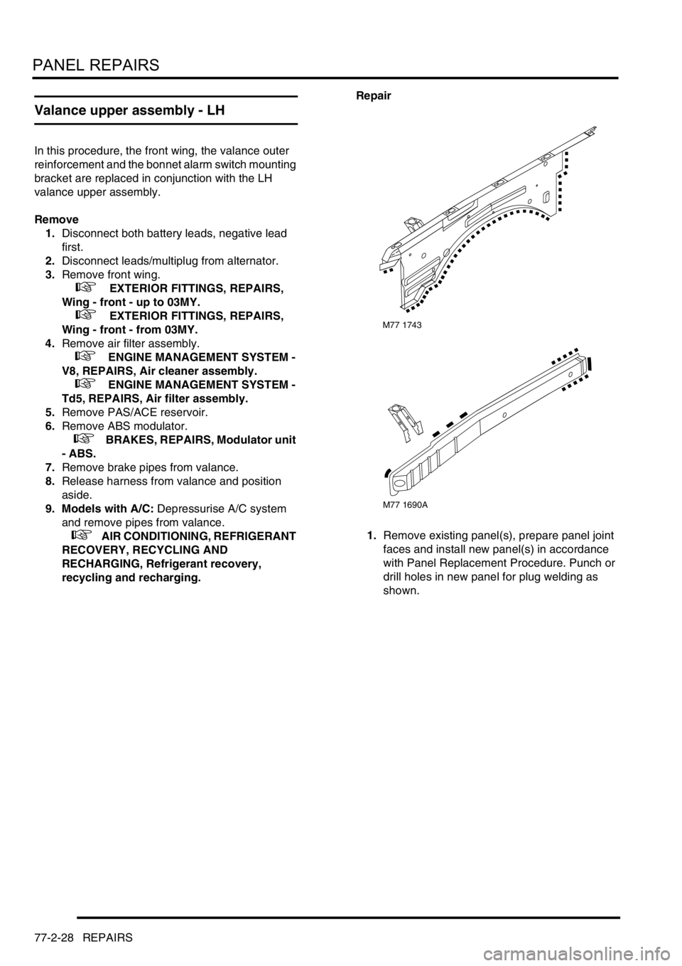
Valance upper assembly - LH
In this procedure, the front wing, the valance outer
reinforcement and the bonnet alarm switch mounting
bracket are replaced in conjunction with the LH
valance upper assembly.
Remove
1.Disconnect both battery leads, negative lead
first.
2.Disconnect leads/multiplug from alternator.
3.Remove front wing.
+ EXTERIOR FITTINGS, REPAIRS,
Wing - front - up to 03MY.
+ EXTERIOR FITTINGS, REPAIRS,
Wing - front - from 03MY.
4.Remove air filter assembly.
+ ENGINE MANAGEMENT SYSTEM -
V8, REPAIRS, Air cleaner assembly.
+ ENGINE MANAGEMENT SYSTEM -
Td5, REPAIRS, Air filter assembly.
5.Remove PAS/ACE reservoir.
6.Remove ABS modulator.
+ BRAKES, REPAIRS, Modulator unit
- ABS.
7.Remove brake pipes from valance.
8.Release harness from valance and position
aside.
9. Models with A/C: Depressurise A/C system
and remove pipes from valance.
+ AIR CONDITIONING, REFRIGERANT
RECOVERY, RECYCLING AND
RECHARGING, Refrigerant recovery,
recycling and recharging.Repair
1.Remove existing panel(s), prepare panel joint
faces and install new panel(s) in accordance
with Panel Replacement Procedure. Punch or
drill holes in new panel for plug welding as
shown.
M77 1743
M77 1690A
Page 1096 of 1529
PANEL REPAIRS
REPAIRS 77-2-29
Refit
1. Models with A/C: Fit A/C pipes and recharge
A/C system.
+ AIR CONDITIONING, REFRIGERANT
RECOVERY, RECYCLING AND
RECHARGING, Refrigerant recovery,
recycling and recharging.
2.Fit harness to valance.
3.Fit brake pipes to valance.
4.Fit ABS modulator.
+ BRAKES, REPAIRS, Modulator unit
- ABS.
5.Fit PAS/ACE reservoir, refill fluids to correct
levelsand bleed ACE system.
+ FRONT SUSPENSION,
ADJUSTMENTS, ACE hydraulic system
bleeding.
+ CAPACITIES, FLUIDS,
LUBRICANTS AND SEALANTS, Fluids.
6.Fit air filter assembly.
+ ENGINE MANAGEMENT SYSTEM -
V8, REPAIRS, Air cleaner assembly.
+ ENGINE MANAGEMENT SYSTEM -
Td5, REPAIRS, Air filter assembly.
7.Fit front wing.
+ EXTERIOR FITTINGS, REPAIRS,
Wing - front - up to 03MY.
+ EXTERIOR FITTINGS, REPAIRS,
Wing - front - from 03MY.
8.Connect leads/multiplug to alternator.
9.Connect battery leads, negative lead last.
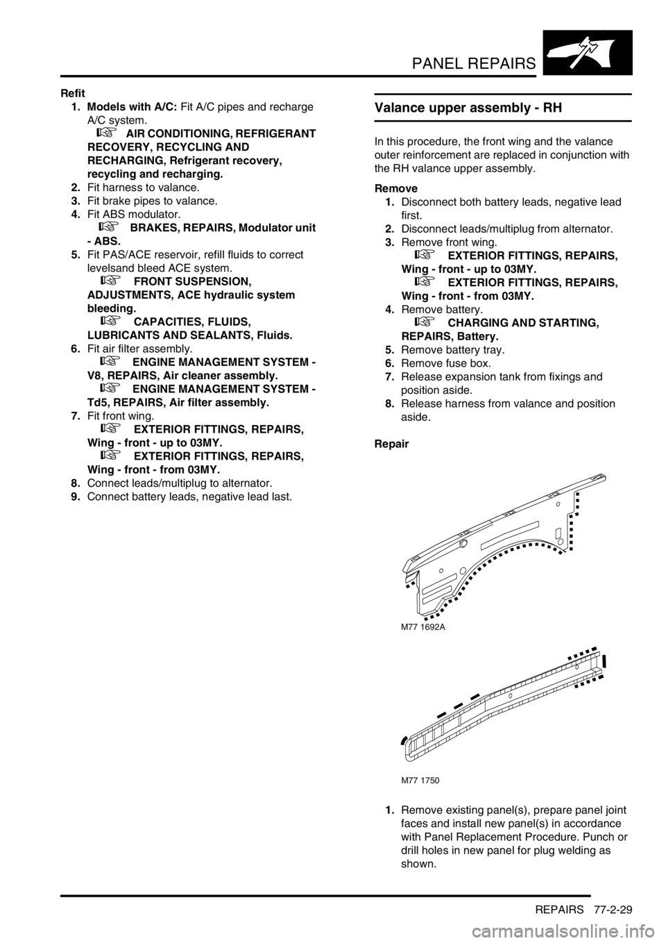
Valance upper assembly - RH
In this procedure, the front wing and the valance
outer reinforcement are replaced in conjunction with
the RH valance upper assembly.
Remove
1.Disconnect both battery leads, negative lead
first.
2.Disconnect leads/multiplug from alternator.
3.Remove front wing.
+ EXTERIOR FITTINGS, REPAIRS,
Wing - front - up to 03MY.
+ EXTERIOR FITTINGS, REPAIRS,
Wing - front - from 03MY.
4.Remove battery.
+ CHARGING AND STARTING,
REPAIRS, Battery.
5.Remove battery tray.
6.Remove fuse box.
7.Release expansion tank from fixings and
position aside.
8.Release harness from valance and position
aside.
Repair
1.Remove existing panel(s), prepare panel joint
faces and install new panel(s) in accordance
with Panel Replacement Procedure. Punch or
drill holes in new panel for plug welding as
shown.
M77 1692A
M77 1750
Page 1097 of 1529
PANEL REPAIRS
77-2-30 REPAIRS
Refit
1.Fit harness to valance.
2.Fit and secure expansion tank to fixings.
3.Fit fuse box.
4.Fit battery tray.
5.Fit battery.
+ CHARGING AND STARTING,
REPAIRS, Battery.
6.Fit front wing.
+ EXTERIOR FITTINGS, REPAIRS,
Wing - front - up to 03MY.
+ EXTERIOR FITTINGS, REPAIRS,
Wing - front - from 03MY.
7.Connect leads/multiplug to alternator.
8.Connect battery leads, negative lead last.
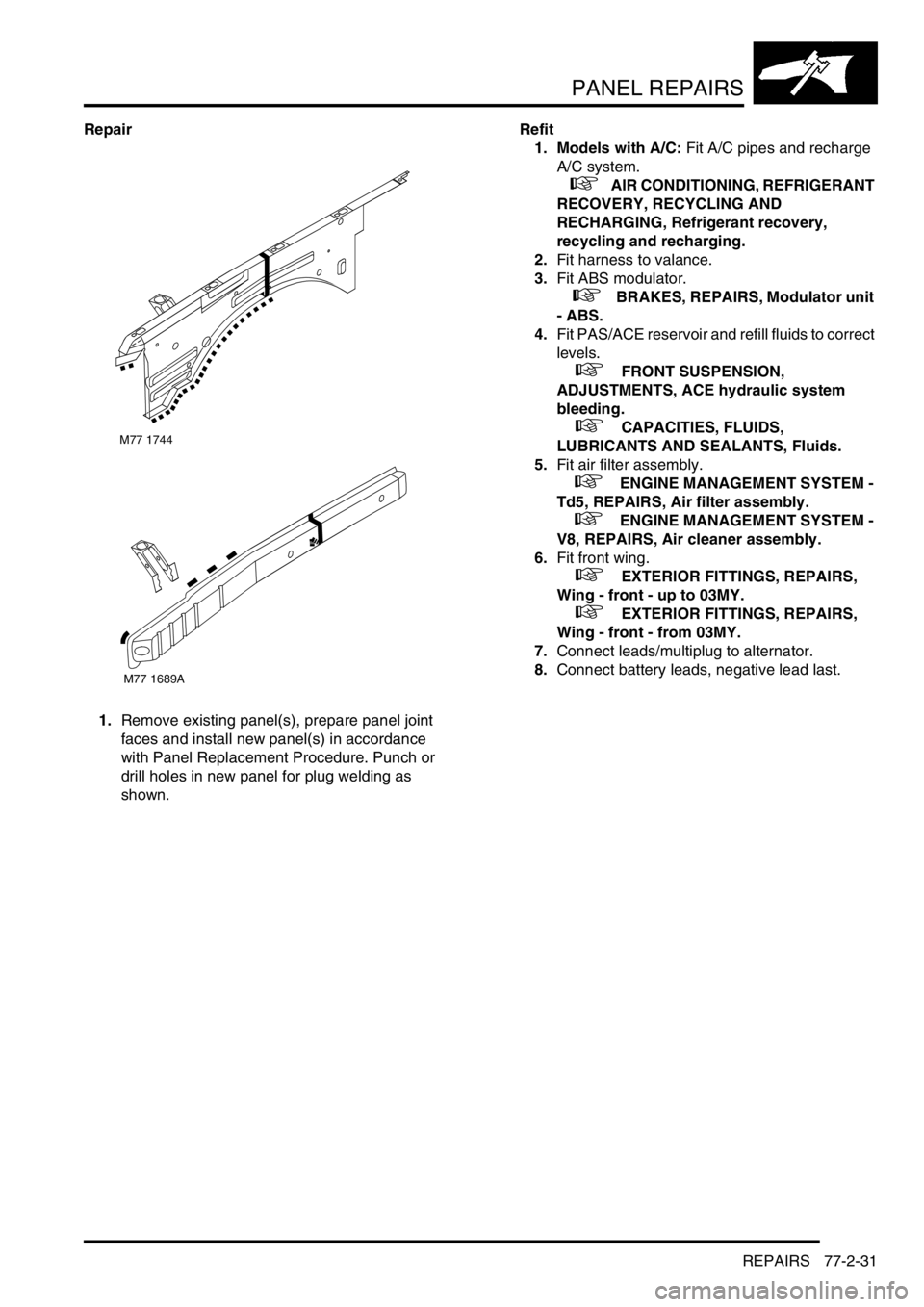
Valance upper assembly (front section) -
LH
In this procedure, the front wing, the valance outer
reinforcement (front section) and the bonnet alarm
switch mounting bracket are replaced in conjunction
with the LH valance upper assembly (front section).
Remove
1.Disconnect both battery leads, negative lead
first.
2.Disconnect leads/multiplug from alternator.
3.Remove front wing.
+ EXTERIOR FITTINGS, REPAIRS,
Wing - front - up to 03MY.
+ EXTERIOR FITTINGS, REPAIRS,
Wing - front - from 03MY.
4.Remove air filter assembly.
+ ENGINE MANAGEMENT SYSTEM -
Td5, REPAIRS, Air filter assembly.
+ ENGINE MANAGEMENT SYSTEM -
V8, REPAIRS, Air cleaner assembly.
5.Remove PAS/ACE reservoir.
6.Remove ABS modulator.
+ BRAKES, REPAIRS, Modulator unit
- ABS.
7.Release harness from valance and position
aside.
8. Models with A/C: Depressurise A/C system
and remove pipes from valance.
+ AIR CONDITIONING, REFRIGERANT
RECOVERY, RECYCLING AND
RECHARGING, Refrigerant recovery,
recycling and recharging.
Page 1098 of 1529
PANEL REPAIRS
REPAIRS 77-2-31
Repair
1.Remove existing panel(s), prepare panel joint
faces and install new panel(s) in accordance
with Panel Replacement Procedure. Punch or
drill holes in new panel for plug welding as
shown.Refit
1. Models with A/C: Fit A/C pipes and recharge
A/C system.
+ AIR CONDITIONING, REFRIGERANT
RECOVERY, RECYCLING AND
RECHARGING, Refrigerant recovery,
recycling and recharging.
2.Fit harness to valance.
3.Fit ABS modulator.
+ BRAKES, REPAIRS, Modulator unit
- ABS.
4.Fit PAS/ACE reservoir and refill fluids to correct
levels.
+ FRONT SUSPENSION,
ADJUSTMENTS, ACE hydraulic system
bleeding.
+ CAPACITIES, FLUIDS,
LUBRICANTS AND SEALANTS, Fluids.
5.Fit air filter assembly.
+ ENGINE MANAGEMENT SYSTEM -
Td5, REPAIRS, Air filter assembly.
+ ENGINE MANAGEMENT SYSTEM -
V8, REPAIRS, Air cleaner assembly.
6.Fit front wing.
+ EXTERIOR FITTINGS, REPAIRS,
Wing - front - up to 03MY.
+ EXTERIOR FITTINGS, REPAIRS,
Wing - front - from 03MY.
7.Connect leads/multiplug to alternator.
8.Connect battery leads, negative lead last.
M77 1744
M77 1689A
Page 1101 of 1529
PANEL REPAIRS
77-2-34 REPAIRS
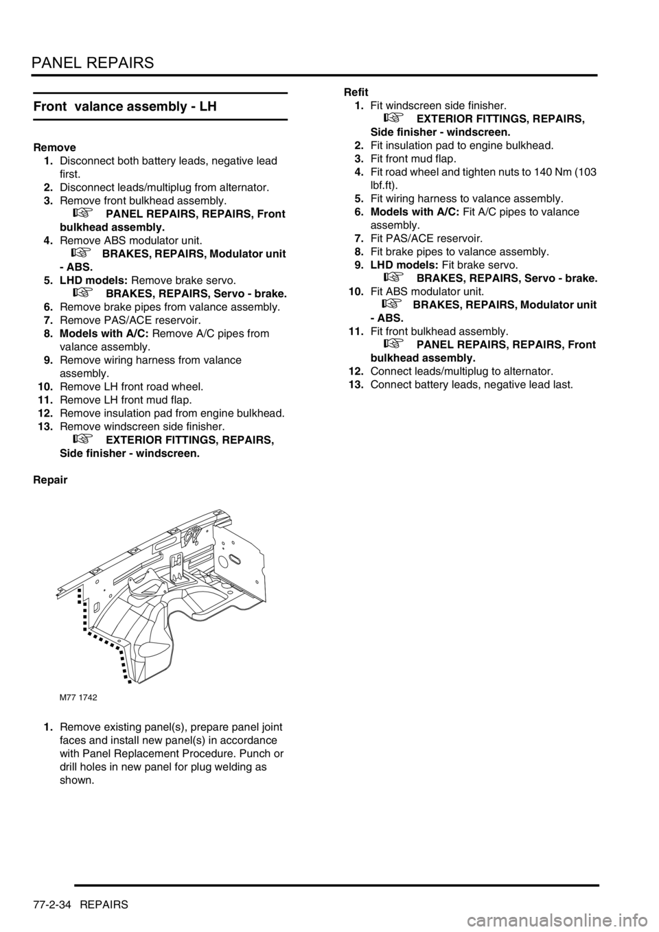
Front valance assembly - LH
Remove
1.Disconnect both battery leads, negative lead
first.
2.Disconnect leads/multiplug from alternator.
3.Remove front bulkhead assembly.
+ PANEL REPAIRS, REPAIRS, Front
bulkhead assembly.
4.Remove ABS modulator unit.
+ BRAKES, REPAIRS, Modulator unit
- ABS.
5. LHD models: Remove brake servo.
+ BRAKES, REPAIRS, Servo - brake.
6.Remove brake pipes from valance assembly.
7.Remove PAS/ACE reservoir.
8. Models with A/C: Remove A/C pipes from
valance assembly.
9.Remove wiring harness from valance
assembly.
10.Remove LH front road wheel.
11.Remove LH front mud flap.
12.Remove insulation pad from engine bulkhead.
13.Remove windscreen side finisher.
+ EXTERIOR FITTINGS, REPAIRS,
Side finisher - windscreen.
Repair
1.Remove existing panel(s), prepare panel joint
faces and install new panel(s) in accordance
with Panel Replacement Procedure. Punch or
drill holes in new panel for plug welding as
shown.Refit
1.Fit windscreen side finisher.
+ EXTERIOR FITTINGS, REPAIRS,
Side finisher - windscreen.
2.Fit insulation pad to engine bulkhead.
3.Fit front mud flap.
4.Fit road wheel and tighten nuts to 140 Nm (103
lbf.ft).
5.Fit wiring harness to valance assembly.
6. Models with A/C: Fit A/C pipes to valance
assembly.
7.Fit PAS/ACE reservoir.
8.Fit brake pipes to valance assembly.
9. LHD models: Fit brake servo.
+ BRAKES, REPAIRS, Servo - brake.
10.Fit ABS modulator unit.
+ BRAKES, REPAIRS, Modulator unit
- ABS.
11.Fit front bulkhead assembly.
+ PANEL REPAIRS, REPAIRS, Front
bulkhead assembly.
12.Connect leads/multiplug to alternator.
13.Connect battery leads, negative lead last.
M77 1742