1999 LAND ROVER DISCOVERY fuse
[x] Cancel search: fusePage 1390 of 1529
IN CAR ENTERTAINMENT
DESCRIPTION AND OPERATION 86-6-23
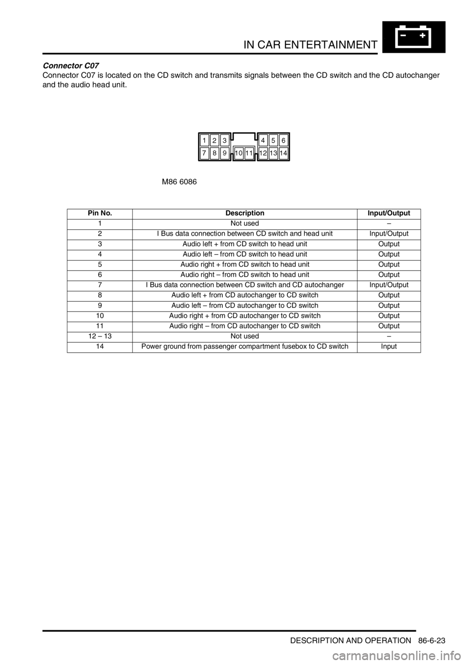
Connector C07
Connector C07 is located on the CD switch and transmits signals between the CD switch and the CD autochanger
and the audio head unit.
Pin No. Description Input/Output
1 Not used–
2 I Bus data connection between CD switch and head unit Input/Output
3 Audio left + from CD switch to head unit Output
4 Audio left – from CD switch to head unit Output
5 Audio right + from CD switch to head unit Output
6 Audio right – from CD switch to head unit Output
7 I Bus data connection between CD switch and CD autochanger Input/Output
8 Audio left + from CD autochanger to CD switch Output
9 Audio left – from CD autochanger to CD switch Output
10 Audio right + from CD autochanger to CD switch Output
11 Audio right – from CD autochanger to CD switch Output
12 – 13 Not used–
14 Power ground from passenger compartment fusebox to CD switch Input
Page 1393 of 1529
IN CAR ENTERTAINMENT
86-6-26 DESCRIPTION AND OPERATION
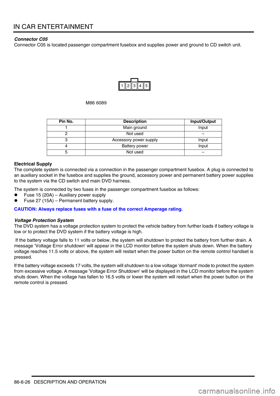
Connector C05
Connector C05 is located passenger compartment fusebox and supplies power and ground to CD switch unit.
Electrical Supply
The complete system is connected via a connection in the passenger compartment fusebox. A plug is connected to
an auxiliary socket in the fusebox and supplies the ground, accessory power and permanent battery power supplies
to the system via the CD switch and main DVD harness.
The system is connected by two fuses in the passenger compartment fusebox as follows:
lFuse 15 (20A) – Auxiliary power supply
lFuse 27 (15A) – Permanent battery supply.
CAUTION: Always replace fuses with a fuse of the correct Amperage rating.
Voltage Protection System
The DVD system has a voltage protection system to protect the vehicle battery from further loads if battery voltage is
low or to protect the DVD system if the battery voltage is high.
If the battery voltage falls to 11 volts or below, the system will shutdown to protect the battery from further drain. A
message 'Voltage Error shutdown' will appear in the LCD monitor before the system shuts down. When the battery
voltage reaches 11.5 volts or above, the system will restart when the power button on the remote control handset is
pressed.
If the battery voltage exceeds 17 volts, the system will shutdown to a low voltage 'dormant' mode to protect the system
from excessive voltage. A message 'Voltage Error Shutdown' will be displayed in the LCD monitor before the system
shuts down. When the voltage has fallen to 16.5 volts or lower the system will restart when the power button on the
remote control is pressed.
Pin No. Description Input/Output
1 Main ground Input
2 Not used–
3 Accessory power supply Input
4 Battery power Input
5 Not used–
Page 1395 of 1529

IN CAR ENTERTAINMENT
86-6-28 DESCRIPTION AND OPERATION
Fault Finding
The following table details potential faults, possible causes and rectification suggestions.
Fault Possible Cause Rectification
System fails to power up Missing or blown fuse Check both fuses in passenger compartment fusebox
Battery voltage too low or too high Voltage protection system may be active. Check battery
voltage output
Faulty connections Check all DVD harness connections for security and
correct location of pins
Faulty overhead console Replace overhead console
Damaged DVD harness Check all DVD harnesses for damage and repair or
replace as required
Faulty noise filter connection Check power supply wires into and out of the noise filter
on the CD switch box
No picture or sound Missing or blown fuse Check both fuses in passenger compartment fusebox
Low or high battery voltage Check battery voltage output
Vehicle interior is too hot or too
coldAllow vehicle interior to warm up or cool down before
switching on the system
DVD parental rating system is
preventing DVD playRefer to DVD System Owner's Manual and check the
parental control rating setting
LCD monitor is pushed too far
forwardReturn LCD monitor to an angle for normal viewing
Good picture, no sound Volume setting on audio head unit
too lowCheck and adjust head unit volume control
Headphone not connected, faulty
headphone or headphone volume
control incorrectly setEnsure headphone is correctly connected.
Check headphone for correct operation.
check headphone remote volume control setting.
Faulty connections Check all DVD harness connections for security and
correct location of pins
CD switch box or harness fault Check all harnesses to and from the CD switch box. If
harnesses OK, replace CD switch
Faulty overhead console Replace overhead console
Good sound, poor or no
pictureVehicle interior is too cold Allow the vehicle interior to warm up before switching on
the system
Source mode set incorrectly Press the 'Source' button on the remote handset to set
the correct operating mode
Faulty overhead console Replace overhead console
Remote control handset
does not functionCheck batteries in remote control
handsetReplace batteries with new batteries
Ensure that infra-red sensor on
overhead console is not
obstructedLower LCD monitor and check that sensor is not
obstructed or dirty
Status LED on overhead
console is flashingVehicle interior is too hot allow vehicle interior to cool down before switching on
the system
Audio through vehicle
speakers but not through
wired headphonesFaulty headphones Check headphone for correct operation.
Faulty overhead console Replace overhead console
Audio through vehicle
speakers but not through
wireless headphonesFaulty batteries in wireless
headphonesReplace batteries
Faulty headphones Test with known operational headphones and replace
headphones if necessary
Faulty RF transmitter or connector Replace overhead console
Faulty overhead console Replace overhead console
Page 1396 of 1529

IN CAR ENTERTAINMENT
DESCRIPTION AND OPERATION 86-6-29
Audio through headphones
but not through vehicle
speakersFaulty connections a CD switch
boxCheck DVD harnesses and connectors into and out of
the CD switch box
CD switch box internal switches
incorrectly setCheck internal switches on CD switch box for correct
settings for vehicle audio head unit
Faulty CD autochanger (if fitted) Check and if necessary replace CD autochanger
Faulty CD switch box Check and replace CD switch box
Audio CD autochanger does
not operateMissing or blown fuse Check both fuses in passenger compartment fusebox
DVD system speaker setting
incorrectPress speaker button on overhead console or remote
control handset to switch from DVD audio to head unit
CD audio
Faulty audio connections Check all connectors from the audio head unit to the CD
autochanger
Faulty CD autochanger Replace CD autochanger
Faulty CD switch box connections Check CD switch box connectors for security and
correct location of pins
Faulty CD switch box Replace CD switch box
Faulty main DVD harness Check main DVD harness for damage and repair or
replace as necessary
Faulty overhead console Replace overhead console
Overhead console DVD
player will not accept discsMissing or blown fuse Check both fuses in passenger compartment fusebox
Faulty or damaged disc check disc and try a known operational disc
Faulty overhead console Replace overhead console
Page 1405 of 1529
IN CAR ENTERTAINMENT
86-6-38 REPAIRS
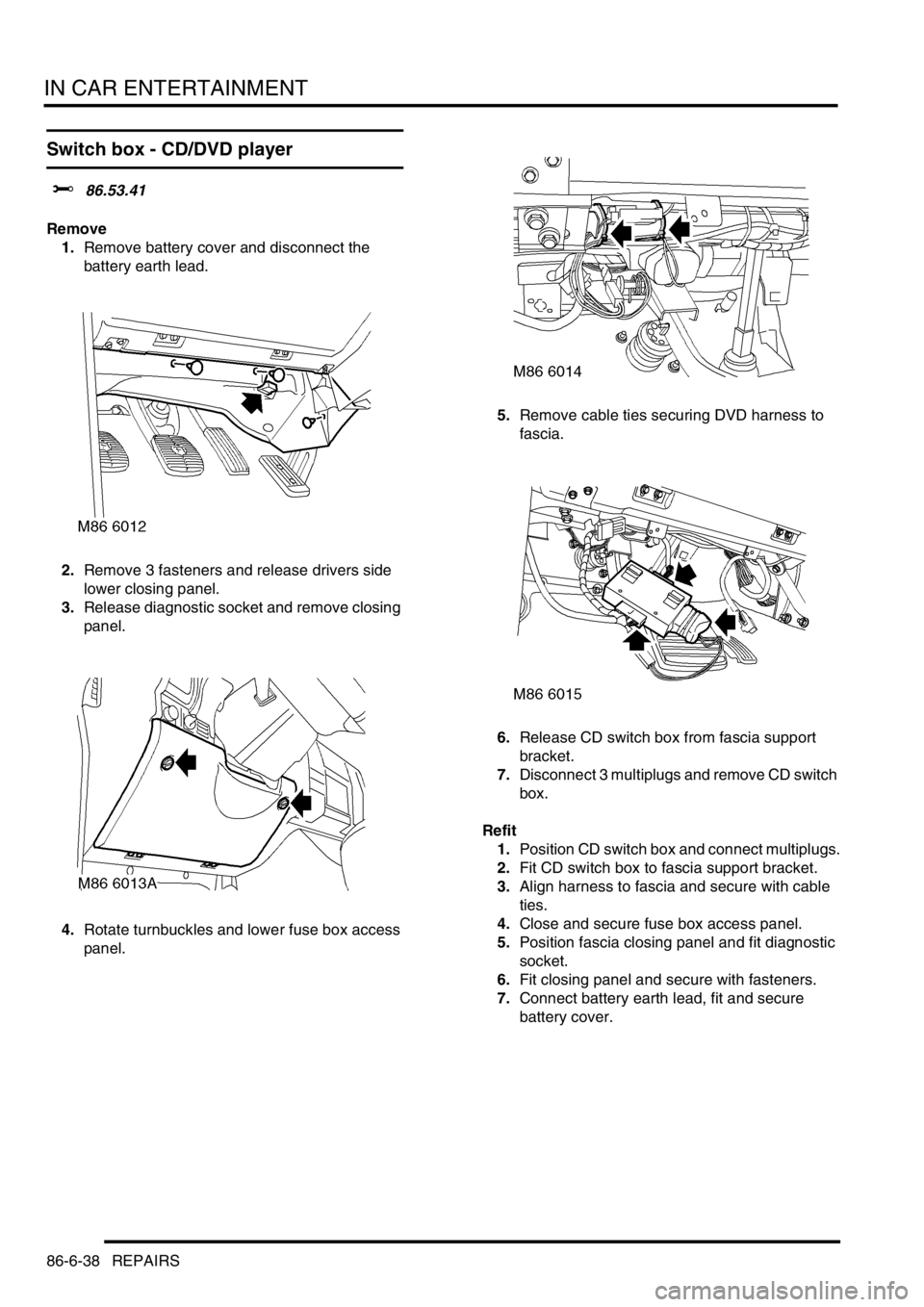
Switch box - CD/DVD player
$% 86.53.41
Remove
1.Remove battery cover and disconnect the
battery earth lead.
2.Remove 3 fasteners and release drivers side
lower closing panel.
3.Release diagnostic socket and remove closing
panel.
4.Rotate turnbuckles and lower fuse box access
panel.5.Remove cable ties securing DVD harness to
fascia.
6.Release CD switch box from fascia support
bracket.
7.Disconnect 3 multiplugs and remove CD switch
box.
Refit
1.Position CD switch box and connect multiplugs.
2.Fit CD switch box to fascia support bracket.
3.Align harness to fascia and secure with cable
ties.
4.Close and secure fuse box access panel.
5.Position fascia closing panel and fit diagnostic
socket.
6.Fit closing panel and secure with fasteners.
7.Connect battery earth lead, fit and secure
battery cover.
Page 1415 of 1529
HARNESSES
86-7-10 REPAIRS
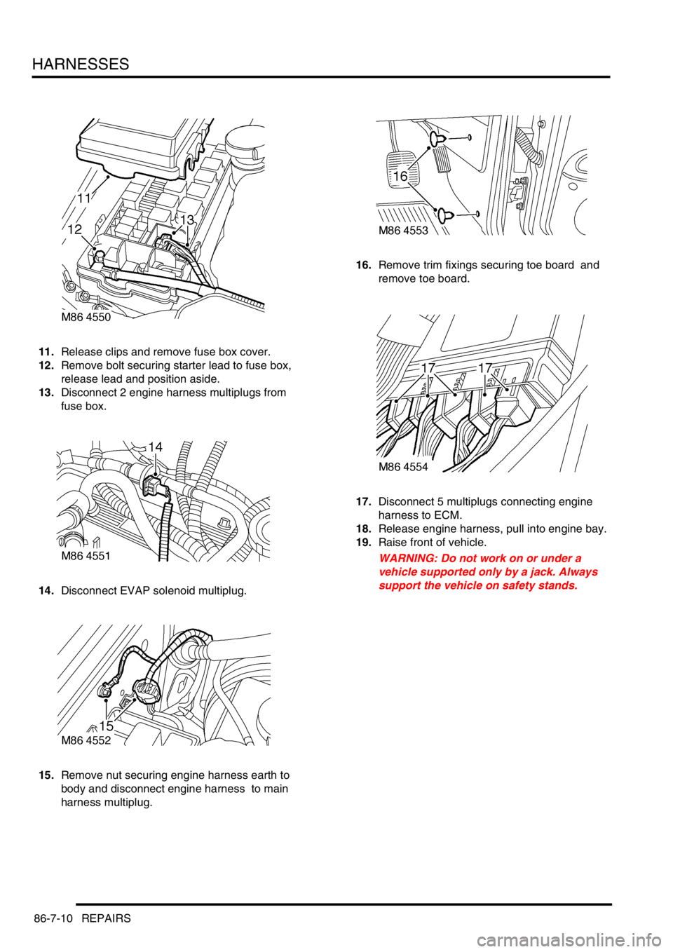
11.Release clips and remove fuse box cover.
12.Remove bolt securing starter lead to fuse box,
release lead and position aside.
13.Disconnect 2 engine harness multiplugs from
fuse box.
14.Disconnect EVAP solenoid multiplug.
15.Remove nut securing engine harness earth to
body and disconnect engine harness to main
harness multiplug. 16.Remove trim fixings securing toe board and
remove toe board.
17.Disconnect 5 multiplugs connecting engine
harness to ECM.
18.Release engine harness, pull into engine bay.
19.Raise front of vehicle.
WARNING: Do not work on or under a
vehicle supported only by a jack. Always
support the vehicle on safety stands.
Page 1417 of 1529
HARNESSES
86-7-12 REPAIRS
Refit
1.Position engine harness around engine.
2.Connect oil pressure switch and camshaft
sensor multiplugs.
3.Fit and tighten bolt securing harness to LH side
of engine.
4.Connect both knock sensor multiplugs.
5.Connect battery cable and solenoid cable to
starter motor.
6.Position starter heat shield and secure with
bolt.
7.Clean exhaust flange mating faces, using a
new gasket align exhaust fit nuts and tighten to
60 Nm (44 lbf.ft).
8.Remove stand(s) and lower vehicle.
9.Position harness into footwell and secure
grommet.
10.Connect ECM multiplugs.
11.Position toe board and secure with trim fixings.
12.Connect engine harness to main harness
multiplug and secure earth lead.
13.Connect EVAP solenoid multiplug.
14.Connect both fuse box multiplugs.
15.Position starter lead to fuse box and secure
screw.
16.Fit fuse box cover.
17.Position battery positive lead to battery and
secure nut.
18.Secure harness to coolant rail.
19.Position alternator cables and tighten terminal
B+ to 18 Nm (13 lbf.ft) and terminal D+ to 5 Nm
(3.7 lbf.ft)
20.Connect coolant temperature sensor multiplug.
21.Connect A/C compressor multiplug.
22.Secure harness clip to rear of LH cylinder head.
23.Connect CKP sensor multiplug.
24.Secure injector harness and connect injector
multiplugs.
25.Connect coil multiplugs.
26.Connect and secure HS
2O sensor multiplug
27.Fit upper inlet manifold.
+ MANIFOLDS AND EXHAUST
SYSTEMS - V8, REPAIRS, Gasket - inlet
manifold - upper - Without Secondary Air
Injection.
28.Connect battery earth lead.
Harness - engine - diesel
$% 86.70.17
Remove
1.Remove engine acoustic cover.
2.Remove battery carrier.
+ CHARGING AND STARTING,
REPAIRS, Battery carrier.
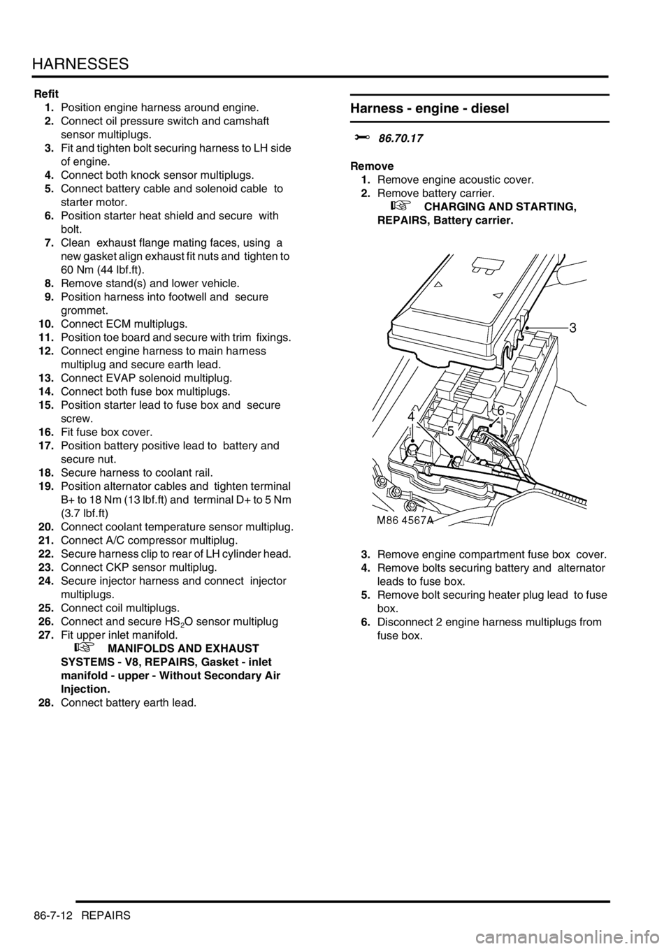
3.Remove engine compartment fuse box cover.
4.Remove bolts securing battery and alternator
leads to fuse box.
5.Remove bolt securing heater plug lead to fuse
box.
6.Disconnect 2 engine harness multiplugs from
fuse box.
Page 1420 of 1529
HARNESSES
REPAIRS 86-7-15
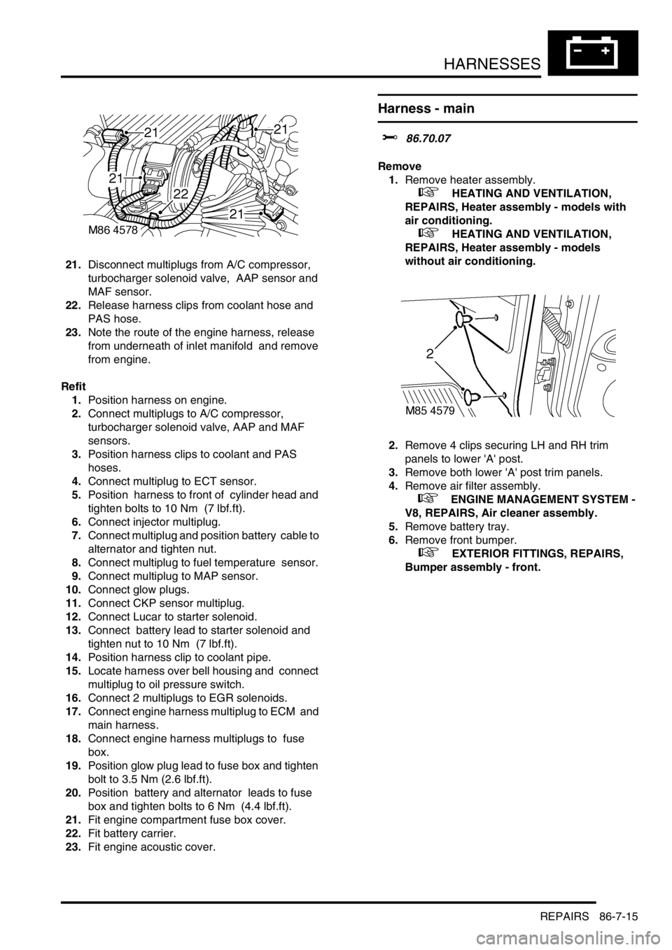
21.Disconnect multiplugs from A/C compressor,
turbocharger solenoid valve, AAP sensor and
MAF sensor.
22.Release harness clips from coolant hose and
PAS hose.
23.Note the route of the engine harness, release
from underneath of inlet manifold and remove
from engine.
Refit
1.Position harness on engine.
2.Connect multiplugs to A/C compressor,
turbocharger solenoid valve, AAP and MAF
sensors.
3.Position harness clips to coolant and PAS
hoses.
4.Connect multiplug to ECT sensor.
5.Position harness to front of cylinder head and
tighten bolts to 10 Nm (7 lbf.ft).
6.Connect injector multiplug.
7.Connect multiplug and position battery cable to
alternator and tighten nut.
8.Connect multiplug to fuel temperature sensor.
9.Connect multiplug to MAP sensor.
10.Connect glow plugs.
11.Connect CKP sensor multiplug.
12.Connect Lucar to starter solenoid.
13.Connect battery lead to starter solenoid and
tighten nut to 10 Nm (7 lbf.ft).
14.Position harness clip to coolant pipe.
15.Locate harness over bell housing and connect
multiplug to oil pressure switch.
16.Connect 2 multiplugs to EGR solenoids.
17.Connect engine harness multiplug to ECM and
main harness.
18.Connect engine harness multiplugs to fuse
box.
19.Position glow plug lead to fuse box and tighten
bolt to 3.5 Nm (2.6 lbf.ft).
20.Position battery and alternator leads to fuse
box and tighten bolts to 6 Nm (4.4 lbf.ft).
21.Fit engine compartment fuse box cover.
22.Fit battery carrier.
23.Fit engine acoustic cover.
Harness - main
$% 86.70.07
Remove
1.Remove heater assembly.
+ HEATING AND VENTILATION,
REPAIRS, Heater assembly - models with
air conditioning.
+ HEATING AND VENTILATION,
REPAIRS, Heater assembly - models
without air conditioning.
2.Remove 4 clips securing LH and RH trim
panels to lower 'A' post.
3.Remove both lower 'A' post trim panels.
4.Remove air filter assembly.
+ ENGINE MANAGEMENT SYSTEM -
V8, REPAIRS, Air cleaner assembly.
5.Remove battery tray.
6.Remove front bumper.
+ EXTERIOR FITTINGS, REPAIRS,
Bumper assembly - front.