1999 LAND ROVER DISCOVERY service
[x] Cancel search: servicePage 1394 of 1529
IN CAR ENTERTAINMENT
DESCRIPTION AND OPERATION 86-6-27
Operation
DVD Player Functionality
The following defines the functionality of the unit. Further details of system operation can found in the DVD System
Owner's Manual, Publication Part No. LRL0482, supplied with the system.
DVD Region Selection
The DVD player is capable of playing discs from any region. The DVD can only be set to play discs of one region at
a time. A code is entered using the remote control handset to set the unit to the required region. The unit is set to the
correct region on production and therefore this will not be required by either the dealer or the customer.
If the unit region is required to be changed for any reason, Land Rover Special Vehicles must be contacted for the
required code and procedure.
NOTE: The unit can be re-configured for region up to five times. After the fifth attempt to re-configure the region, the
unit will be locked in the fifth region that was programmed. This will require the unit to be returned to the manufacturer
to be reset. The manufacturer will charge a fee for this service.
DVD Player CD Audio Function
The DVD player can play audio CD's through the vehicle audio system. This allows the user to play additional CD's
without having to remove the CD autochanger cartridge.
The overhead console LCD monitor must be open to play audio CD's.. Normal audio CD functionality such as repeat,
random and track select etc. can be accessed using the remote control handset.
The DVD player in the overhead console will also function independently of the vehicle audio system, and operate as
an additional CD player. The rear seat passengers can listen to audio CD's via the three headphone sockets on the
overhead console and via the two radio/headphone amplifier units (if fitted), while the front seat passengers
simultaneously listen to CD's played on the vehicle audio system and CD autochanger.
DVD/CD Output using the Vehicle Audio System
To play the DVD/CD audio output from the overhead console through the vehicle audio speakers, the speaker button
on the overhead console or remote control handset must be pressed. 'Speaker On' appears on the LCD monitor and
the head unit CD functionality is suspended. The audio output from the overhead console will now be played from the
vehicle speaker system. The head unit volume control, tone control, Navigation announcements and mobile phone (if
fitted) will function as normal and override the DVD output. A second press of the speaker button will switch the audio
output back to the head unit. 'Speaker Off' will be displayed on the LCD monitor.
The overhead console will remember the selected speaker condition if the overhead console is switched off by closing
the monitor, the console switched off using the handset or accessory power removed from the overhead console.
Power Up Conditions
On application of accessory power, the overhead console will perform the following:
lIf no disc is in the DVD player, the LCD monitor will display a blue screen and enter 'AUX' input mode.
When a DVD or CD is inserted in the DVD player, the system will change to DVD input mode. The disc will
attempt to play but may be limited by the disc media. Some discs will play automatically, some will display a menu
and others require the user to start playback.
lIf a disc was in the DVD player and the system was in 'Play', 'Pause', 'FF' or 'Rew' when powered down, playback
will start when power is re-applied.
lIf a disc was in the DVD player and the system was in 'Stop' when powered down, the system will enter DVD
mode and a blue screen will be displayed on the LCD monitor.
lSpeaker selection will remain in the same state as when the accessory power was removed.
Engine Cranking
If the unit is playing a DVD or CD when the ignition switch is moved to position III (engine crank), the system will stop
playing while the engine is cranking. Playback will resume at the point the playback was stopped when the ignition
switch is returned to position I or II.
Page 1456 of 1529
NAVIGATION SYSTEM
DESCRIPTION AND OPERATION 87-3
Navigation Computer
The navigation computer is installed in the DIN radio slot in the fascia. A spring loaded catch on each side of the
navigation computer secures it in position. Slide tools, installed in slots at the bottom front corners of the navigation
computer, are required to unlock the catches during removal.
The navigation computer contains all the hardware and software required for control of the navigation, radio and CD
systems, including the GPS receiver and a solid state piezo gyro for the navigation system. The piezo gyro measures
the motion of the vehicle around its vertical axis.
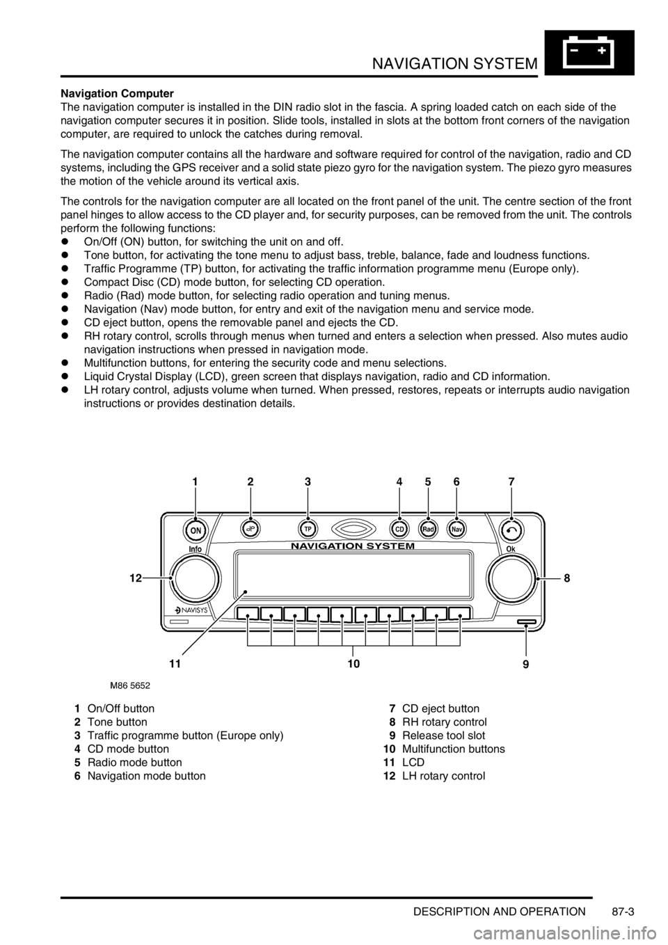
The controls for the navigation computer are all located on the front panel of the unit. The centre section of the front
panel hinges to allow access to the CD player and, for security purposes, can be removed from the unit. The controls
perform the following functions:
lOn/Off (ON) button, for switching the unit on and off.
lTone button, for activating the tone menu to adjust bass, treble, balance, fade and loudness functions.
lTraffic Programme (TP) button, for activating the traffic information programme menu (Europe only).
lCompact Disc (CD) mode button, for selecting CD operation.
lRadio (Rad) mode button, for selecting radio operation and tuning menus.
lNavigation (Nav) mode button, for entry and exit of the navigation menu and service mode.
lCD eject button, opens the removable panel and ejects the CD.
lRH rotary control, scrolls through menus when turned and enters a selection when pressed. Also mutes audio
navigation instructions when pressed in navigation mode.
lMultifunction buttons, for entering the security code and menu selections.
lLiquid Crystal Display (LCD), green screen that displays navigation, radio and CD information.
lLH rotary control, adjusts volume when turned. When pressed, restores, repeats or interrupts audio navigation
instructions or provides destination details.
1On/Off button
2Tone button
3Traffic programme button (Europe only)
4CD mode button
5Radio mode button
6Navigation mode button7CD eject button
8RH rotary control
9Release tool slot
10Multifunction buttons
11LCD
12LH rotary control
Page 1459 of 1529
NAVIGATION SYSTEM
87-6 DESCRIPTION AND OPERATION
Service Menu
The service menu provides access to details of the navigation computer hardware and software, and can be accessed
when the navigation computer is in radio mode, by simultaneously pressing the NAV button and the 10 multifunction
buttons. The following items can then be scrolled through by pressing the Nxt (next) and Prv (previous) multifunction
buttons, or turning the RH rotary control:
lModel No.
lSerial No.
lChanger Reset
lGAL
lRadio Software
lRadio Bolo
lNavi Rom
lNavi Flash
lRTC Value
When Changer Reset is displayed, the CD autochanger (where fitted) can be reset by pressing the appropriate
multifunction button.
When the End multifunction button is pressed, the navigation computer quits the service menu and returns to radio
mode.
Garage Menu
Garage menu enables the navigation system to be tested and calibrated, and also contains a route navigation
demonstration. The garage menu is entered from the main navigation menu, as follows:
1Press the Nav button to access the system settings.
2Press and hold multifunction button 3, then press multifunction button 5 to display the garage menu.
The garage menu contains the following, which can be accessed using the RH rotary control:
lCALIBRATION RIDE – Used to calibrate the navigation computer, to enable route navigation.
lGPS INFO– Provides functional test of antenna by checking GPS reception. If functioning correctly, displays the
number of satellites being received, the date, time (Greenwich Mean Time) and the type of positional fix currently
possible.
lCALIBRATION– Allows vehicle specific calibration data to be entered, e.g. tyre size. Also allows current
calibration to be deleted prior to re-calibrating.
NOTE: Only known calibration data should be entered. The navigation computer cannot make route
calculations if incorrect data is entered.
lSENSORS– Allows wheel speed, reverse gear and gyro sensor inputs to be checked.
lVERSION– Displays navigation computer hardware and software details.
lSPEECH TEST– Performs a test of the navigation computer audio output.
lMODULE TEST– Performs a test routine on the internal components of the navigation computer.
lDEMO – Allows a route navigation demonstration to be run.
To quit the garage menu, press the Nav button.
Page 1473 of 1529
NAVIGATION SYSTEM
87-20 DESCRIPTION AND OPERATION
Operation
General
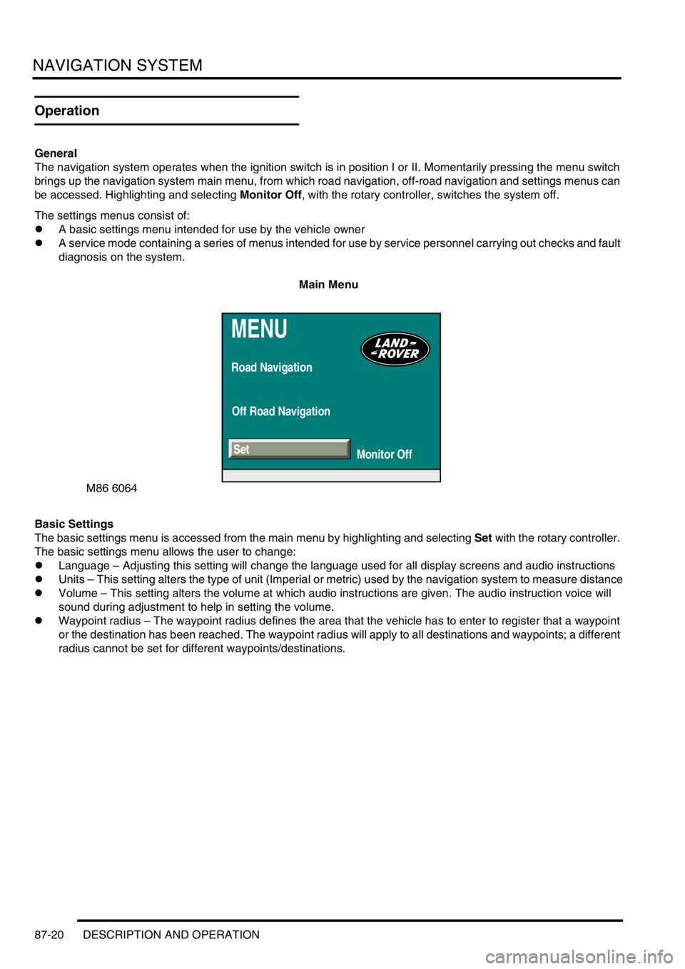
The navigation system operates when the ignition switch is in position I or II. Momentarily pressing the menu switch
brings up the navigation system main menu, from which road navigation, off-road navigation and settings menus can
be accessed. Highlighting and selecting Monitor Off, with the rotary controller, switches the system off.
The settings menus consist of:
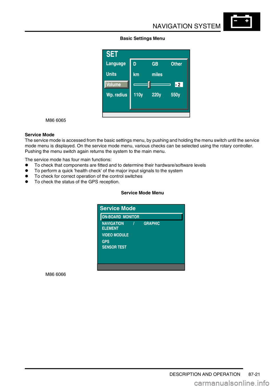
lA basic settings menu intended for use by the vehicle owner
lA service mode containing a series of menus intended for use by service personnel carrying out checks and fault
diagnosis on the system.
Main Menu
Basic Settings
The basic settings menu is accessed from the main menu by highlighting and selecting Set with the rotary controller.
The basic settings menu allows the user to change:
lLanguage – Adjusting this setting will change the language used for all display screens and audio instructions
lUnits – This setting alters the type of unit (Imperial or metric) used by the navigation system to measure distance
lVolume – This setting alters the volume at which audio instructions are given. The audio instruction voice will
sound during adjustment to help in setting the volume.
lWaypoint radius – The waypoint radius defines the area that the vehicle has to enter to register that a waypoint
or the destination has been reached. The waypoint radius will apply to all destinations and waypoints; a different
radius cannot be set for different waypoints/destinations.
MENU
Road Navigation
Off Road Navigation
Monitor Off
M86 6064
Set
Page 1474 of 1529
NAVIGATION SYSTEM
DESCRIPTION AND OPERATION 87-21
Basic Settings Menu
Service Mode
The service mode is accessed from the basic settings menu, by pushing and holding the menu switch until the service
mode menu is displayed. On the service mode menu, various checks can be selected using the rotary controller.
Pushing the menu switch again returns the system to the main menu.
The service mode has four main functions:
lTo check that components are fitted and to determine their hardware/software levels
lTo perform a quick 'health check' of the major input signals to the system
lTo check for correct operation of the control switches
lTo check the status of the GPS reception.
Service Mode Menu
SET
Units Language
D
km
110y 220y 550ymilesGB Other
Volume
Wp. radius
- 2
M86 6065
M86 6066
ON-BOARD MONITOR
NAVIGATION / GRAPHIC
ELEMENT
VIDEO MODULE
GPS
Service Mode
SENSOR TEST
Page 1475 of 1529
NAVIGATION SYSTEM
87-22 DESCRIPTION AND OPERATION
On-Board Monitor (Display Unit)
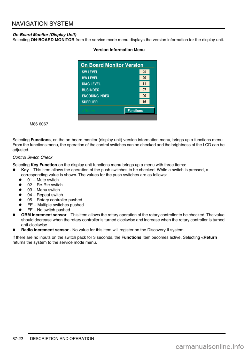
Selecting ON-BOARD MONITOR from the service mode menu displays the version information for the display unit.
Version Information Menu
Selecting Functions, on the on-board monitor (display unit) version information menu, brings up a functions menu.
From the functions menu, the operation of the control switches can be checked and the brightness of the LCD can be
adjusted.
Control Switch Check
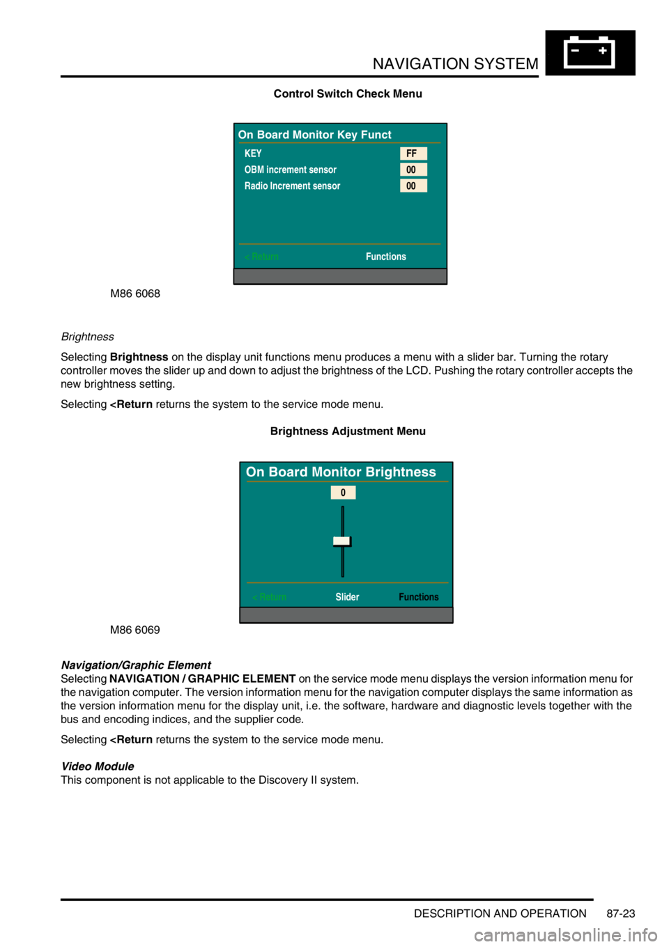
Selecting Key Function on the display unit functions menu brings up a menu with three items:
lKey – This item allows the operation of the push switches to be checked. While a switch is pressed, a
corresponding value is shown. The values for the push switches are as follows:
l01 – Mute switch
l02 – Re-Rte switch
l03 – Menu switch
l04 – Repeat switch
l05 – Rotary controller pushed
lFE – Multiple switches pushed
lFF – No switch pushed
lOBM increment sensor – This item allows the rotary operation of the rotary controller to be checked. The value
should decrease when the rotary controller is turned clockwise and increase when the rotary controller is turned
anti-clockwise
lRadio increment sensor - No value for this item will register on the Discovery II system.
If there are no inputs on the switch pack for 3 seconds, the Functions item becomes active. Selecting
M86 6067
On Board Monitor Version
SW LEVEL
HW LEVEL
DIAG LEVEL
BUS INDEX
ENCODING INDEX
SUPPLIER
< Return25
20
11
07
00
16
Functions
Page 1476 of 1529
NAVIGATION SYSTEM
DESCRIPTION AND OPERATION 87-23
Control Switch Check Menu
Brightness
Selecting Brightness on the display unit functions menu produces a menu with a slider bar. Turning the rotary
controller moves the slider up and down to adjust the brightness of the LCD. Pushing the rotary controller accepts the
new brightness setting.
Selecting
Navigation/Graphic Element
Selecting NAVIGATION / GRAPHIC ELEMENT on the service mode menu displays the version information menu for
the navigation computer. The version information menu for the navigation computer displays the same information as
the version information menu for the display unit, i.e. the software, hardware and diagnostic levels together with the
bus and encoding indices, and the supplier code.
Selecting
This component is not applicable to the Discovery II system.
M86 6068
On Board Monitor Key Funct
KEY
OBM increment sensor
Radio Increment sensor
< ReturnFF
00
00
Functions
M86 6069
On Board Monitor Brightness
< Return SliderFunctions
0
Page 1477 of 1529
NAVIGATION SYSTEM
87-24 DESCRIPTION AND OPERATION
GPS
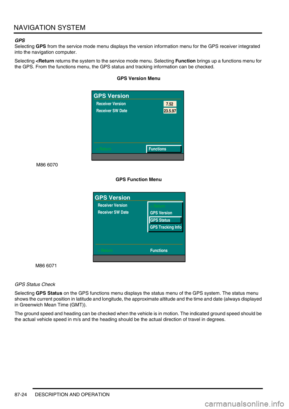
Selecting GPS from the service mode menu displays the version information menu for the GPS receiver integrated
into the navigation computer.
Selecting
GPS Version Menu
GPS Function Menu
GPS Status Check
Selecting GPS Status on the GPS functions menu displays the status menu of the GPS system. The status menu
shows the current position in latitude and longitude, the approximate altitude and the time and date (always displayed
in Greenwich Mean Time (GMT)).
The ground speed and heading can be checked when the vehicle is in motion. The indicated ground speed should be
the actual vehicle speed in m/s and the heading should be the actual direction of travel in degrees.
M86 6070
GPS Version
Receiver Version
Receiver SW Date
< Return7.52
Functions
23.5.97
M86 6071
GPS Version
Receiver Version
Receiver SW Date
< ReturnFunctions< Return
GPS Version
GPS Status
GPS Tracking Info