1999 LAND ROVER DISCOVERY service
[x] Cancel search: servicePage 1479 of 1529

NAVIGATION SYSTEM
87-26 DESCRIPTION AND OPERATION
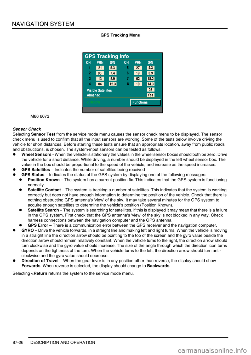
GPS Tracking Menu
Sensor Check
Selecting Sensor Test from the service mode menu causes the sensor check menu to be displayed. The sensor
check menu is used to confirm that all the input sensors are working. Some of the tests below involve driving the
vehicle for short distances. Before starting these tests ensure that an appropriate location, away from public roads
and obstructions, is chosen. The system-input sensors can be tested as follows:
lWheel Sensors - When the vehicle is stationary the values in the wheel sensor boxes should both be zero. Drive
the vehicle for a short distance. While driving, a number should be displayed in the left wheel sensor box. The
value in the box should be proportional to the speed of the vehicle, and increase as the speed increases.
lGPS Satellites – Indicates the number of satellites being received
lGPS Status – Indicates the status of the GPS system by displaying one of the following messages:
lPosition Known – The system has a current position fix. This indicates that the GPS system is functioning
normally.
lSatellite Contact – The system is tracking a number of satellites. This indicates that the system is working
correctly but does not have enough information to determine the position of the vehicle. Check that there is
nothing obstructing GPS antenna's 'view' of the sky. It may take several minutes for the GPS system to
acquire enough satellites to determine the vehicle's position (Position Known).
lSatellite Search – The system is searching for satellites. If this is displayed it may mean that there is a failure
in the GPS system. First check that the GPS antenna's 'view' of the sky is not blocked in any way. Check
harness connections between the navigation computer and the GPS antenna.
lGPS Error – There is a communication error between the GPS receiver and the navigation computer.
lGYRO – Drive the vehicle forwards, in a straight line and making left and right turns. When the vehicle is moving
in a straight line the direction arrow should be pointing to the top of the screen and the gyro value beside the
direction arrow should remain relatively constant. When the vehicle turns to the right, the direction arrow should
turn clockwise and the gyro value should increase. The size of the angle through which the direction icon turns
depends on the tightness of the turn. When the vehicle turns to the left, the direction arrow should turn anti-
clockwise and the gyro value should decrease.
lDirection of Travel – When the gear lever is in any position other than reverse, the display should show
Forwards. When reverse is selected, the display should change to Backwards.
Selecting
GPS Tracking Info
1
2
3
4
Visible Satellites
Almanac
< Return
08
Yes
Functions 5.3 21
7.4 05
5.9
13
12.3
04CHPRN
S/N
CHPRN
S/N
4.3
27
3.9 19
18.2 02
14.3 10 5
6
7
8
Page 1488 of 1529

INSTRUMENTS
DESCRIPTION AND OPERATION 88-5
Description
General
The instrument pack consists of four analogue dials, four warning lamp packs and a Liquid Crystal Display (LCD)
odometer.
The four dials are used to indicate:
lRoad speed.
lEngine speed.
lFuel tank level.
lEngine coolant temperature.
The dials are driven by a microprocessor from information received from the serial communication link. Information
input is received as either:
lDigital.
lAnalogue.
lPulse train.
lPulse Width Modulation (PWM).
The LCD provides information for:
lOdometer.
lTrip distance.
lSelected gear (on vehicles fitted with an automatic gearbox).
A trip reset button is provided to zero the trip display, this button also allows the selection of "miles" or "kilometres"
for the display. A photocell controls the illumination of the LCD, maintaining contrast of the display during ambient light
changes.
Within the four warning lamp packs there are 28 lamps. A long life bulb illuminates the high beam warning lamp and
the rest of the warning lamps are illuminated by Light Emitting Diodes (LED's). All warning lamp legends are invisible
until lit. When lit the symbols are illuminated on a black background.
The warning lamps illuminate in one of four colours. The colour indicates the level of importance to the driver, as
follows:
lRed = warning.
lAmber = caution.
lGreen = system operative.
lBlue = main beam operative.
The first warning lamp pack is located in the top left-hand side of the instrument pack and contains the following
warning lamps:
lTraction control warning lamp.
lTransfer box in neutral warning lamp.
lDifferential lock warning lamp
lOverspeed warning lamp (activated for gulf market only).
lBrake system warning lamp.
lHill Descent Control (HDC) information warning lamp.
lMalfunction Indicator Lamp (MIL)/ SERVICE ENGINE SOON warning lamp.
The second warning lamp pack is located in the centre of the instrument pack and contains the following warning
lamps:
lDirection indicator warning lamps.
lHigh beam warning lamp.
lAnti-lock brake system warning lamp.
Page 1495 of 1529

INSTRUMENTS
88-12 DESCRIPTION AND OPERATION
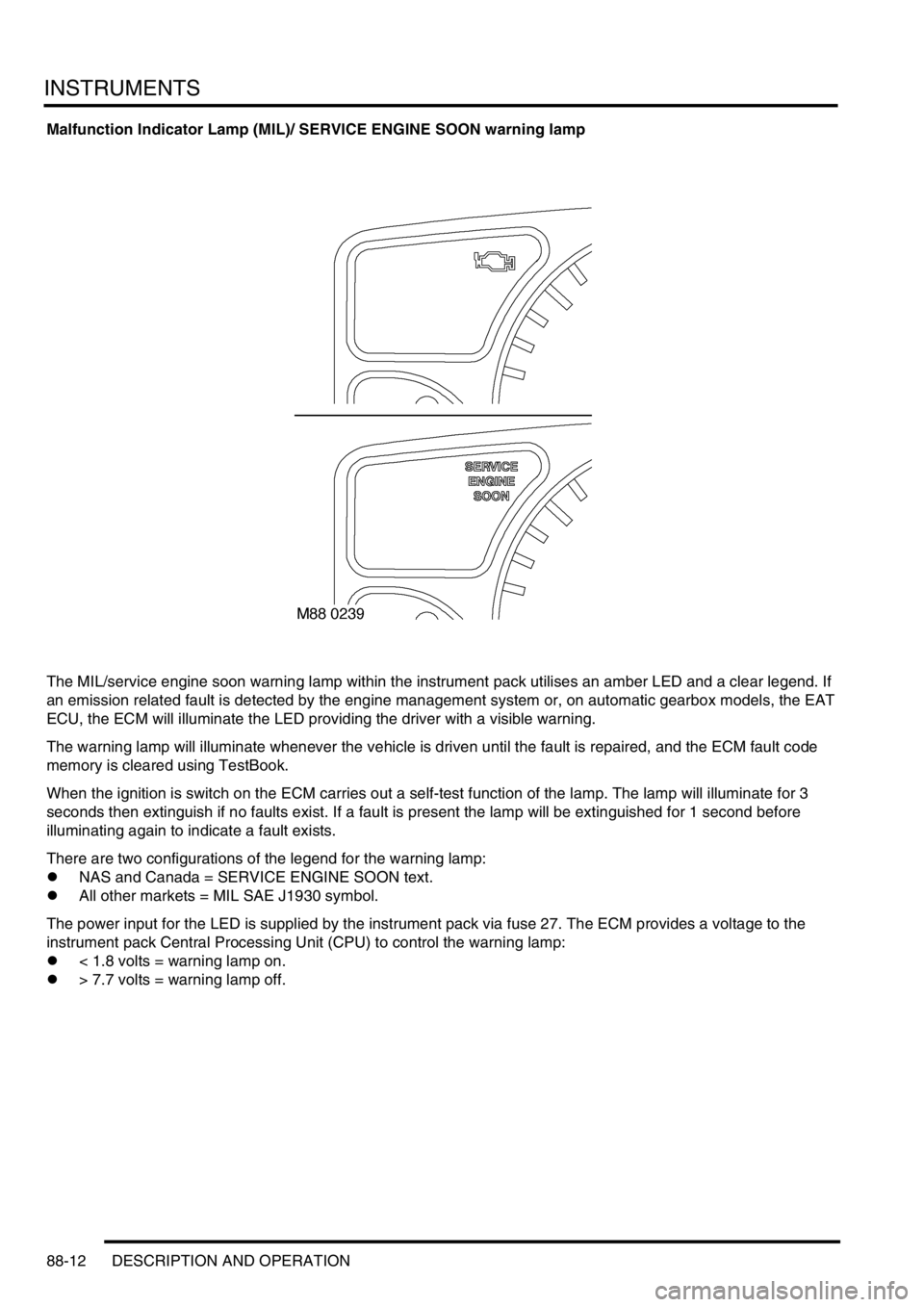
Malfunction Indicator Lamp (MIL)/ SERVICE ENGINE SOON warning lamp
The MIL/service engine soon warning lamp within the instrument pack utilises an amber LED and a clear legend. If
an emission related fault is detected by the engine management system or, on automatic gearbox models, the EAT
ECU, the ECM will illuminate the LED providing the driver with a visible warning.
The warning lamp will illuminate whenever the vehicle is driven until the fault is repaired, and the ECM fault code
memory is cleared using TestBook.
When the ignition is switch on the ECM carries out a self-test function of the lamp. The lamp will illuminate for 3
seconds then extinguish if no faults exist. If a fault is present the lamp will be extinguished for 1 second before
illuminating again to indicate a fault exists.
There are two configurations of the legend for the warning lamp:
lNAS and Canada = SERVICE ENGINE SOON text.
lAll other markets = MIL SAE J1930 symbol.
The power input for the LED is supplied by the instrument pack via fuse 27. The ECM provides a voltage to the
instrument pack Central Processing Unit (CPU) to control the warning lamp:
l< 1.8 volts = warning lamp on.
l> 7.7 volts = warning lamp off.
Page 1506 of 1529

INSTRUMENTS
DESCRIPTION AND OPERATION 88-23
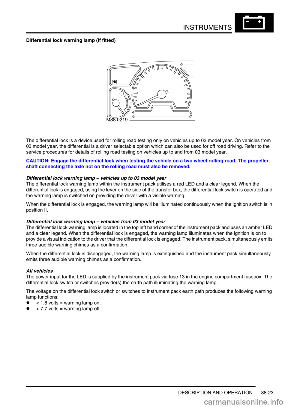
Differential lock warning lamp (If fitted)
The differential lock is a device used for rolling road testing only on vehicles up to 03 model year. On vehicles from
03 model year, the differential is a driver selectable option which can also be used for off road driving. Refer to the
service procedures for details of rolling road testing on vehicles up to and from 03 model year.
CAUTION: Engage the differential lock when testing the vehicle on a two wheel rolling road. The propeller
shaft connecting the axle not on the rolling road must also be removed.
Differential lock warning lamp – vehicles up to 03 model year
The differential lock warning lamp within the instrument pack utilises a red LED and a clear legend. When the
differential lock is engaged, using the lever on the side of the transfer box, the differential lock switch is operated and
the warning lamp is switched on providing the driver with a visible warning.
When the differential lock is engaged, the warning lamp will be illuminated continuously when the ignition switch is in
position II.
Differential lock warning lamp – vehicles from 03 model year
The differential lock warning lamp is located in the top left hand corner of the instrument pack and uses an amber LED
and a clear legend. When the differential lock is engaged, the warning lamp illuminates when the ignition is on to
provide a visual indication to the driver that the differential lock is engaged. The instrument pack, simultaneously emits
three audible warning chimes as a confirmation.
When the differential lock is disengaged, the warning lamp is extinguished and the instrument pack simultaneously
emits three audible warning chimes as a confirmation.
All vehicles
The power input for the LED is supplied by the instrument pack via fuse 13 in the engine compartment fusebox. The
differential lock switch or switches provide(s) the earth path illuminating the warning lamp.
The voltage on the differential lock switch or switches to instrument pack earth path produces the following warning
lamp functions:
l< 1.8 volts = warning lamp on.
l> 7.7 volts = warning lamp off.
Page 1524 of 1529

INSTRUMENTS
DESCRIPTION AND OPERATION 88-41
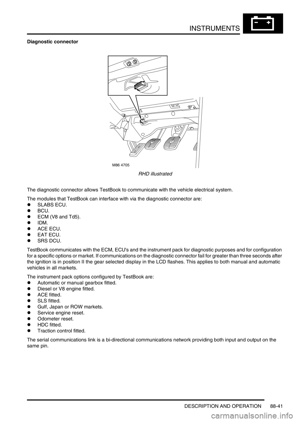
Diagnostic connector
RHD illustrated
The diagnostic connector allows TestBook to communicate with the vehicle electrical system.
The modules that TestBook can interface with via the diagnostic connector are:
lSLABS ECU.
lBCU.
lECM (V8 and Td5).
lIDM.
lACE ECU.
lEAT ECU.
lSRS DCU.
TestBook communicates with the ECM, ECU's and the instrument pack for diagnostic purposes and for configuration
for a specific options or market. If communications on the diagnostic connector fail for greater than three seconds after
the ignition is in position II the gear selected display in the LCD flashes. This applies to both manual and automatic
vehicles in all markets.
The instrument pack options configured by TestBook are:
lAutomatic or manual gearbox fitted.
lDiesel or V8 engine fitted.
lACE fitted.
lSLS fitted.
lGulf, Japan or ROW markets.
lService engine reset.
lOdometer reset.
lHDC fitted.
lTraction control fitted.
The serial communications link is a bi-directional communications network providing both input and output on the
same pin.
M86 4705