1999 LAND ROVER DISCOVERY sat nav
[x] Cancel search: sat navPage 1455 of 1529

NAVIGATION SYSTEM
87-2 DESCRIPTION AND OPERATION
Description
General
The navigation system provides audio and visual route guidance to help the driver reach a selected destination. The
system is an optional fit consisting of a Traffic Pro navigation computer and antenna, manufactured by Harman/
Becker Automotive Systems, which are fitted in place of the In Car Entertainment (ICE) head unit and antenna.
Compact Disc (CD) and radio functions are incorporated into the navigation computer.
The navigation system allows the driver to choose between the shortest and fastest routes between the vehicle's
current position and a selected destination, and to select a stopover point in the journey and a route that avoids
motorways, ferries and toll roads. Directions to Points Of Interest (POI) e.g. airports, hospitals, petrol stations etc,
either local, national or in another country, can also be selected. A traffic jam function enables the driver to request
diversion instructions, around an obstructed part of the selected route, during the journey. A Traffic Management
Control (TMC) function, currently only available in some European countries, monitors traffic broadcasts and
automatically selects an alternative route during the journey if the original route is effected by a traffic jam, accident
or road works etc.
The position of the vehicle is determined by the navigation computer using a combination of vehicle sensor inputs and
radio signals from the 24 Global Positioning System (GPS) satellites orbiting the earth. The position of the vehicle is
then plotted on a digitised map, loaded into the navigation computer from a CD-ROM, to determine the journey route
and provide the route guidance.
The GPS satellite signals are used for initial determination of the vehicle's position and periodic position updates. The
vehicle sensor inputs are used to monitor the vehicle's direction of travel and distance travelled between position
updates from the GPS satellite signals. The vehicle sensor inputs consist of:
lA vehicle speed signal from the ABS ECU, to monitor the distance travelled and for automatic volume control.
lA reverse gear signal from the selector and inhibitor switch of the automatic gearbox, or reverse gear switch of
the manual gearbox, to enable the navigation computer to differentiate between forward and rearward movement
of the vehicle.
lA gyro in the navigation computer, to monitor changes of direction, i.e. steering inputs.
The signal from each GPS satellite contains information about satellite position, almanac data and time (almanac data
is the current status of the satellite). Signals from between five and 11 of the GPS satellites can be received at a given
point on the earth's surface at any one time. The number and quality of separate GPS satellite signals received also
varies with vehicle location. In hilly or tree lined areas, built up areas with tall buildings, multi-storey car parks,
garages, tunnels, bridges and during heavy rain/thunderstorms, signal reception of some or all of the GPS satellites
will be poor or non existent.
A minimum of three separate GPS satellite signals are required for the navigation computer to calculate a three
dimensional (3D) positional fix. When only two signals are being received, the navigation computer will calculate a
less accurate two dimensional (2D) positional fix. The more widely dispersed that the GPS satellites are, the more
accurate the positional fix. The navigation computer can store information from a maximum of 12 GPS satellites at
any one time. When more than three signals are stored, the navigation computer selects the three most widely
dispersed signals for the position calculation.
GPS Antenna and diplexer unit
The GPS antenna is installed at the rear of the roof on the centreline. A diplexer unit on the underside of the GPS
antenna amplifies the radio signals received from the GPS satellites and transmits them through separate dedicated
co-axial cable to the navigation computer for processing.
Page 1458 of 1529

NAVIGATION SYSTEM
DESCRIPTION AND OPERATION 87-5
System Settings Menu
The system settings menu provides access to features that can be changed to suit market and personal preferences
and to navigation system operating features. On European systems, the system settings menu also includes
computer games and a currency converter. While the navigation computer is in the navigation mode, the system
settings menu can be accessed by pressing the Nav button. Using the RH rotary control, the following features can
be selected and adjusted:
lTIME – Allows the navigation system clock to be set to local time as opposed to the Greenwich Mean Time (GMT)
transmitted from the GPS satellites. The local time setting is necessary for correct navigation on routes with time
restrictions and for Estimated Time of Arrival (ETA) calculations. The time can only be adjusted in 30 minute
steps.
lSAVE POSITION– Allows the current vehicle position to be saved and allocated a name in the navigation
destination memory.
lGAMES – Provides access to a selection of computer games.
lLANGUAGE– Allows the navigation system language and voice (where applicable) to be changed.
lANIMATIONS– Allows the LCD animations to be switched on and off.
lMEASURING UNIT – Allows the route guidance distances displayed on the LCD to be switched between metric
and Imperial units.
lANNOUNCEMENT ETA – Allows the route guidance ETA announcement to be switched on and off.
lCALCULATE EURO – Provides access to a currency converter.
User Menu
The user menu provides access to further features that can be changed to suit personal preferences. While the
navigation computer is in navigation, radio or CD modes, the user menu can be accessed by pressing and holding
the tone button for more than 2 seconds. The user menu is displayed over two screens, which can be toggled between
using the ⇒ multifunction button. Using the appropriate multifunction button or the RH rotary control, the following
settings can be selected and adjusted:
Screen 1
lGal – Automatic volume control setting (see above).
lTel – If a handsfree telephone system is connected to the navigation computer, allows either mute (telephone
mute mode) or audio signal (telephone conversation via the ICE speakers) to be selected.
lLcd – The LCD can be set to appear negative, positiveor automatic. In automatic, the display will be positive or
negative, depending on the setting of the exterior lamps.
lLed – A Light Emitting Diode (LED) in the display can be set to off or blinking. When set to blinking, the LED
flashes when the navigation computer is switched off.
lM/S – Radio reception can be set to Stereo, Mono or Auto, to suppress interference and reflections and so
optimise reception. Stereo is for exceptionally good reception conditions. Mono is for poor reception conditions.
In auto, the normal setting, the navigation computer automatically switches between stereo and mono depending
on reception conditions.
Screen 2
lNav – Sets how audio navigation instructions are delivered. In onl, other audio sources are suppressed and only
the navigation instruction is output to the speakers. In mixed, the volume of any other audio source is reduced
and the volume of the navigation announcement is the same as the original audio source +/– 6 dB (adjustable).
In independ, the audio source and navigation announcement can be set to independent volume levels.
lAux – Used to switch auxiliary CD AF connections between Aux mode on and Aux mode off. If no CD
autochanger is installed, an external cassette or CD player can be connected to the navigation computer and
powered by switching on the auxiliary CD AF connections.
lCmp – Allows a compass to be shown on the LCD when route guidance is not active.
lBeV – Used to adjust the signal tone volume. Signal tones sound to confirm storage confirmation etc. and can
be set between 0 (quiet) and +5 (loud).
Page 1459 of 1529

NAVIGATION SYSTEM
87-6 DESCRIPTION AND OPERATION
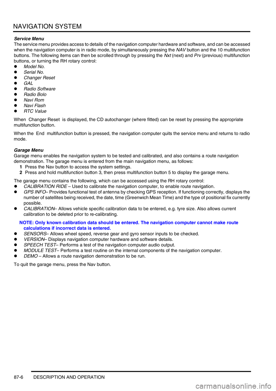
Service Menu
The service menu provides access to details of the navigation computer hardware and software, and can be accessed
when the navigation computer is in radio mode, by simultaneously pressing the NAV button and the 10 multifunction
buttons. The following items can then be scrolled through by pressing the Nxt (next) and Prv (previous) multifunction
buttons, or turning the RH rotary control:
lModel No.
lSerial No.
lChanger Reset
lGAL
lRadio Software
lRadio Bolo
lNavi Rom
lNavi Flash
lRTC Value
When Changer Reset is displayed, the CD autochanger (where fitted) can be reset by pressing the appropriate
multifunction button.
When the End multifunction button is pressed, the navigation computer quits the service menu and returns to radio
mode.
Garage Menu
Garage menu enables the navigation system to be tested and calibrated, and also contains a route navigation
demonstration. The garage menu is entered from the main navigation menu, as follows:
1Press the Nav button to access the system settings.
2Press and hold multifunction button 3, then press multifunction button 5 to display the garage menu.
The garage menu contains the following, which can be accessed using the RH rotary control:
lCALIBRATION RIDE – Used to calibrate the navigation computer, to enable route navigation.
lGPS INFO– Provides functional test of antenna by checking GPS reception. If functioning correctly, displays the
number of satellites being received, the date, time (Greenwich Mean Time) and the type of positional fix currently
possible.
lCALIBRATION– Allows vehicle specific calibration data to be entered, e.g. tyre size. Also allows current
calibration to be deleted prior to re-calibrating.
NOTE: Only known calibration data should be entered. The navigation computer cannot make route
calculations if incorrect data is entered.
lSENSORS– Allows wheel speed, reverse gear and gyro sensor inputs to be checked.
lVERSION– Displays navigation computer hardware and software details.
lSPEECH TEST– Performs a test of the navigation computer audio output.
lMODULE TEST– Performs a test routine on the internal components of the navigation computer.
lDEMO – Allows a route navigation demonstration to be run.
To quit the garage menu, press the Nav button.
Page 1461 of 1529

NAVIGATION SYSTEM
87-8 DESCRIPTION AND OPERATION
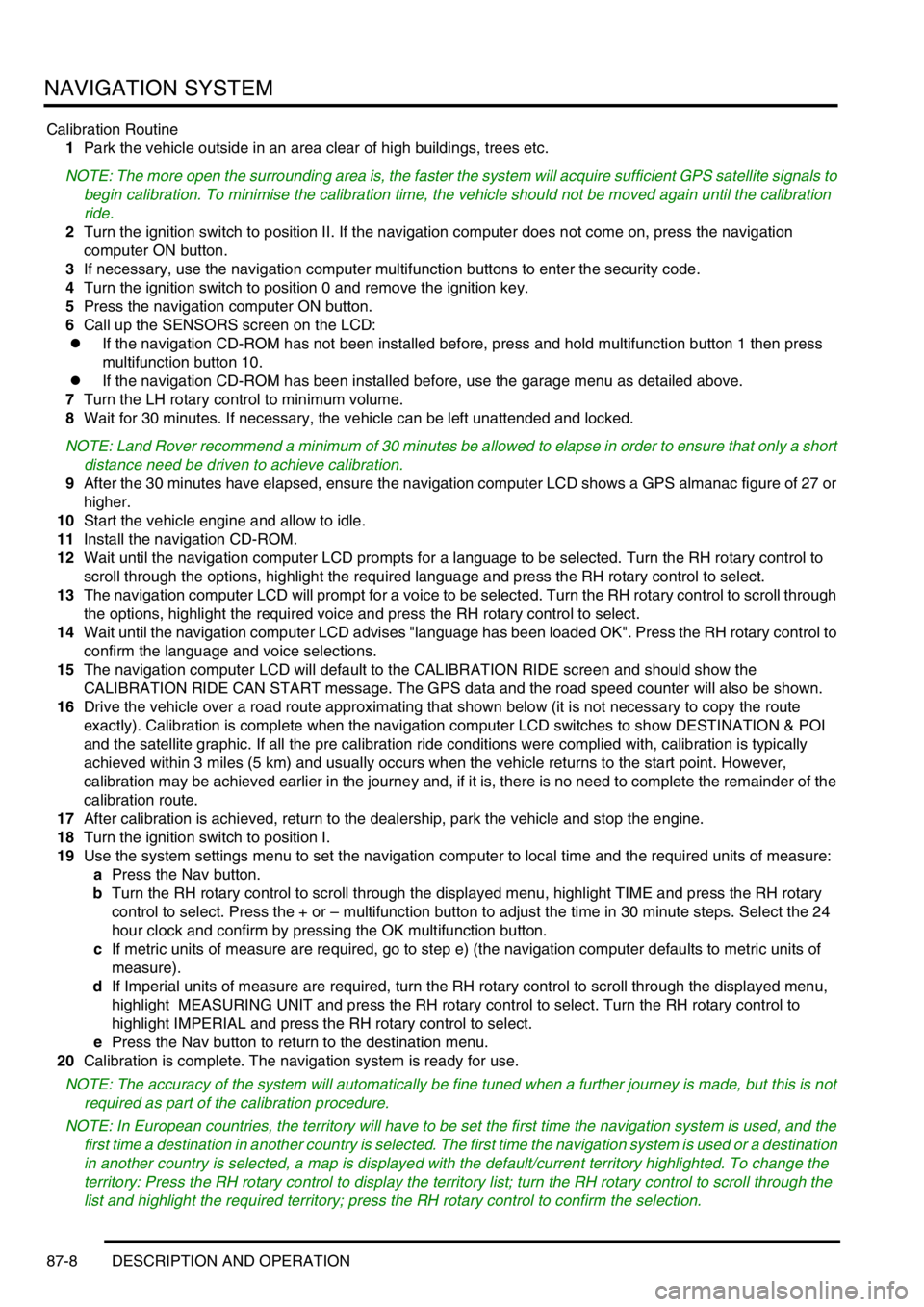
Calibration Routine
1Park the vehicle outside in an area clear of high buildings, trees etc.
NOTE: The more open the surrounding area is, the faster the system will acquire sufficient GPS satellite signals to
begin calibration. To minimise the calibration time, the vehicle should not be moved again until the calibration
ride.
2Turn the ignition switch to position II. If the navigation computer does not come on, press the navigation
computer ON button.
3If necessary, use the navigation computer multifunction buttons to enter the security code.
4Turn the ignition switch to position 0 and remove the ignition key.
5Press the navigation computer ON button.
6Call up the SENSORS screen on the LCD:
lIf the navigation CD-ROM has not been installed before, press and hold multifunction button 1 then press
multifunction button 10.
lIf the navigation CD-ROM has been installed before, use the garage menu as detailed above.
7Turn the LH rotary control to minimum volume.
8Wait for 30 minutes. If necessary, the vehicle can be left unattended and locked.
NOTE: Land Rover recommend a minimum of 30 minutes be allowed to elapse in order to ensure that only a short
distance need be driven to achieve calibration.
9After the 30 minutes have elapsed, ensure the navigation computer LCD shows a GPS almanac figure of 27 or
higher.
10Start the vehicle engine and allow to idle.
11Install the navigation CD-ROM.
12Wait until the navigation computer LCD prompts for a language to be selected. Turn the RH rotary control to
scroll through the options, highlight the required language and press the RH rotary control to select.
13The navigation computer LCD will prompt for a voice to be selected. Turn the RH rotary control to scroll through
the options, highlight the required voice and press the RH rotary control to select.
14Wait until the navigation computer LCD advises "language has been loaded OK". Press the RH rotary control to
confirm the language and voice selections.
15The navigation computer LCD will default to the CALIBRATION RIDE screen and should show the
CALIBRATION RIDE CAN START message. The GPS data and the road speed counter will also be shown.
16Drive the vehicle over a road route approximating that shown below (it is not necessary to copy the route
exactly). Calibration is complete when the navigation computer LCD switches to show DESTINATION & POI
and the satellite graphic. If all the pre calibration ride conditions were complied with, calibration is typically
achieved within 3 miles (5 km) and usually occurs when the vehicle returns to the start point. However,
calibration may be achieved earlier in the journey and, if it is, there is no need to complete the remainder of the
calibration route.
17After calibration is achieved, return to the dealership, park the vehicle and stop the engine.
18Turn the ignition switch to position I.
19Use the system settings menu to set the navigation computer to local time and the required units of measure:
aPress the Nav button.
bTurn the RH rotary control to scroll through the displayed menu, highlight TIME and press the RH rotary
control to select. Press the + or – multifunction button to adjust the time in 30 minute steps. Select the 24
hour clock and confirm by pressing the OK multifunction button.
cIf metric units of measure are required, go to step e) (the navigation computer defaults to metric units of
measure).
dIf Imperial units of measure are required, turn the RH rotary control to scroll through the displayed menu,
highlight MEASURING UNIT and press the RH rotary control to select. Turn the RH rotary control to
highlight IMPERIAL and press the RH rotary control to select.
ePress the Nav button to return to the destination menu.
20Calibration is complete. The navigation system is ready for use.
NOTE: The accuracy of the system will automatically be fine tuned when a further journey is made, but this is not
required as part of the calibration procedure.
NOTE: In European countries, the territory will have to be set the first time the navigation system is used, and the
first time a destination in another country is selected. The first time the navigation system is used or a destination
in another country is selected, a map is displayed with the default/current territory highlighted. To change the
territory: Press the RH rotary control to display the territory list; turn the RH rotary control to scroll through the
list and highlight the required territory; press the RH rotary control to confirm the selection.
Page 1467 of 1529

NAVIGATION SYSTEM
87-14 DESCRIPTION AND OPERATION
Description
General
Where fitted, the CARiN III and Trafficmaster system combines a satellite navigation system (CARiN III) with a real-
time traffic information system (Trafficmaster).
The satellite navigation system provides computer generated audible and visual route guidance information to enable
the driver to reach a desired destination. The system allows the driver to choose between road navigation and off-
road navigation, and to incorporate waypoints. Road navigation also allows the driver to choose between using minor
or major roads and the quickest or shortest route. Directions to hospitals, museums, monuments, hotels etc. are also
available. The computer uses map information stored on a CD-ROM to determine the best route for the journey and
provide the driver with details of directions and approaching junctions. The current position of the vehicle is
determined using a combination of vehicle sensor inputs and the Global Positioning System (GPS).
The Trafficmaster system displays live traffic flow information on the road navigation map screens. Traffic speed is
indicated on the maps by colour coded roads and arrows. The traffic flow information is relayed from a network of
sensors covering motorways and trunk roads. Data from the sensors is updated on a three minute cycle, 24 hours a
day, 365 days a year.
The navigation system consists of the following components:
lNavigation computer
lGPS antenna
lDisplay unit
lSwitch pack
lNavigation speaker
lTrafficmaster monitor ECU
lTrafficmaster antenna
Navigation Computer
The navigation computer is located in a bracket under the RH front seat, immediately behind the CD autochanger.
The navigation computer contains all the hardware and software required for control of the navigation system,
including the GPS receiver and a solid state piezo gyro. Using the gyro, and inputs from the GPS antenna and the
vehicle K bus, the navigation computer determines the vehicle’s current position, direction and speed.
The navigation computer also houses a CD-ROM drive. The drive is used to read map data from country specific CD’s
and also to load software into the computer. A button, adjacent to the CD slot, is provided to eject the CD from the
unit. If the ignition is on, one press of the button will eject the CD. If the ignition is off, two presses are required, one
to wake up the system and the second to eject the CD. Access to the CD-ROM drive is from the rear of the RH front
seat.
Page 1470 of 1529

NAVIGATION SYSTEM
DESCRIPTION AND OPERATION 87-17
GPS Antenna
The GPS antenna is installed on the rear of the roof, on the vehicle centreline. A diplexer unit on the underside of the
GPS antenna amplifies the radio signals received from the GPS satellites and transmits them through a co-axial cable
to the navigation computer for processing.
Display Unit
The display unit is integrated into the front stowage pocket, above the rear view mirror. The display unit is a colour
Liquid Crystal Display (LCD) that shows the programming menus, route guidance and traffic information. The display
illumination level automatically dims for night time viewing when the exterior lights are switched on.
Page 1478 of 1529

NAVIGATION SYSTEM
DESCRIPTION AND OPERATION 87-25
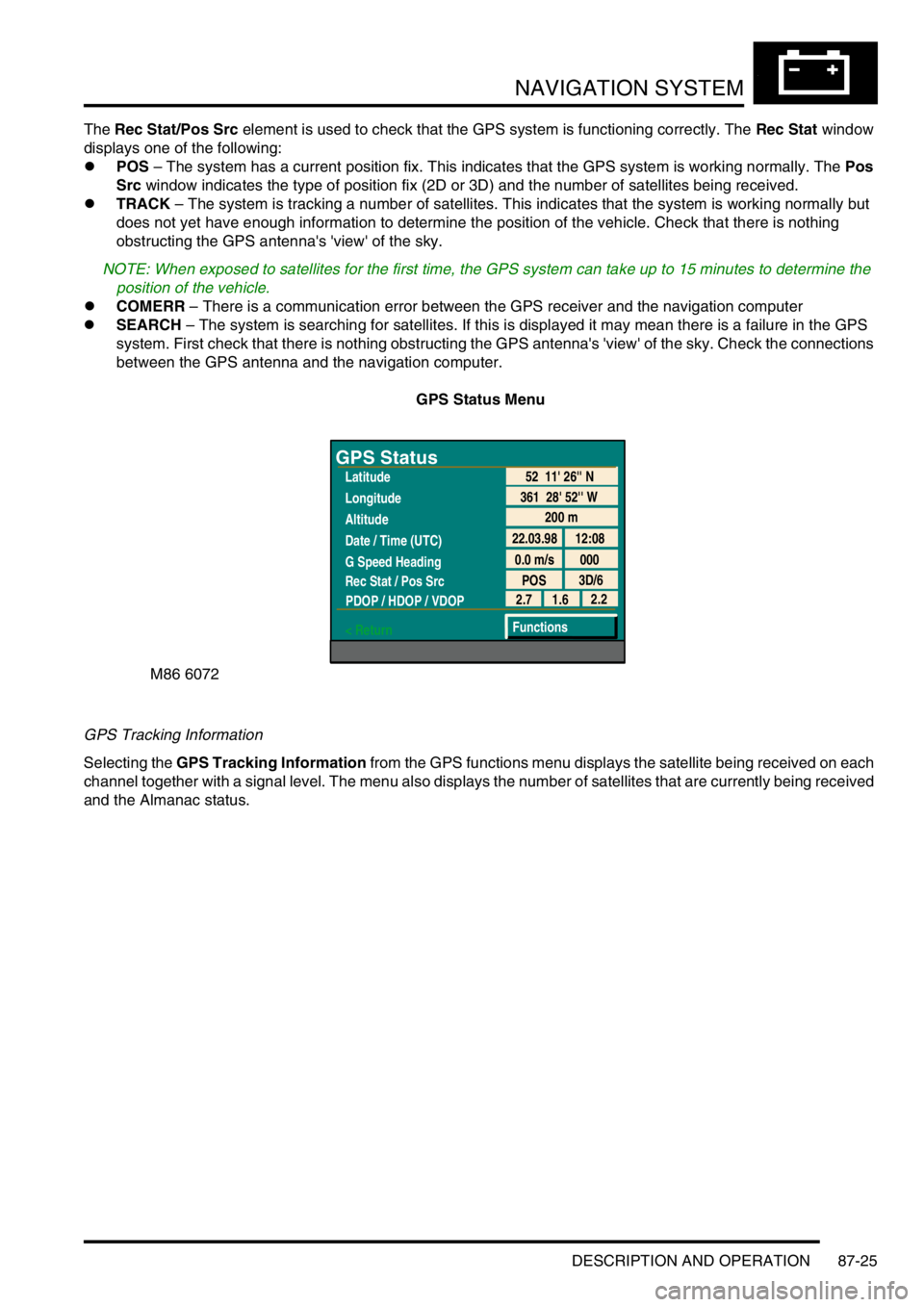
The Rec Stat/Pos Src element is used to check that the GPS system is functioning correctly. The Rec Stat window
displays one of the following:
lPOS – The system has a current position fix. This indicates that the GPS system is working normally. The Pos
Src window indicates the type of position fix (2D or 3D) and the number of satellites being received.
lTRACK – The system is tracking a number of satellites. This indicates that the system is working normally but
does not yet have enough information to determine the position of the vehicle. Check that there is nothing
obstructing the GPS antenna's 'view' of the sky.
NOTE: When exposed to satellites for the first time, the GPS system can take up to 15 minutes to determine the
position of the vehicle.
lCOMERR – There is a communication error between the GPS receiver and the navigation computer
lSEARCH – The system is searching for satellites. If this is displayed it may mean there is a failure in the GPS
system. First check that there is nothing obstructing the GPS antenna's 'view' of the sky. Check the connections
between the GPS antenna and the navigation computer.
GPS Status Menu
GPS Tracking Information
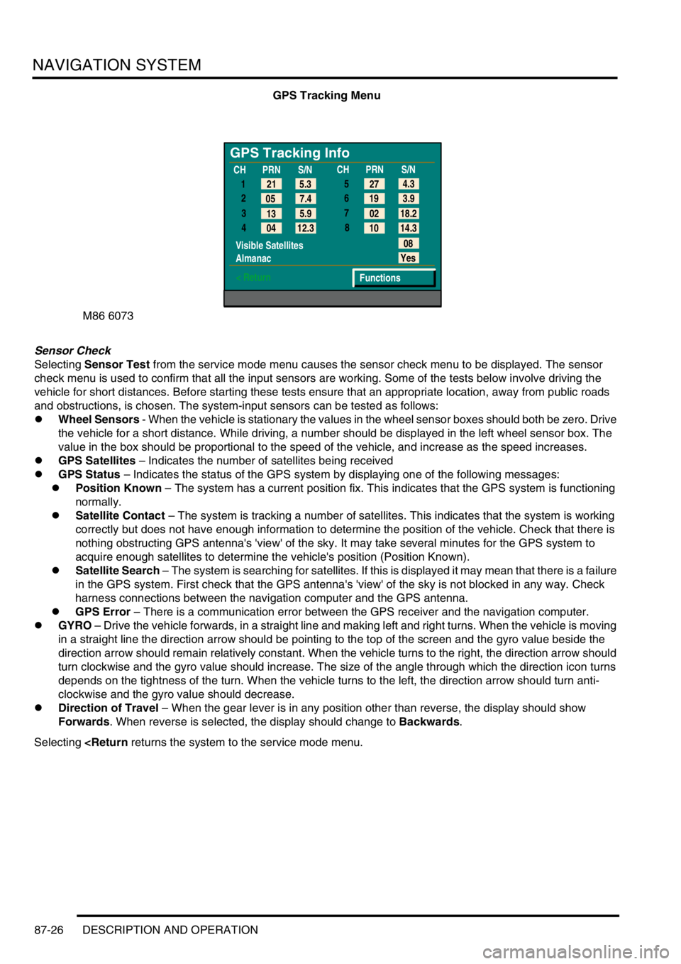
Selecting the GPS Tracking Information from the GPS functions menu displays the satellite being received on each
channel together with a signal level. The menu also displays the number of satellites that are currently being received
and the Almanac status.
M86 6072
GPS Status
Latitude
Longitude
Altitude
Date / Time (UTC)
G Speed Heading
Rec Stat / Pos Src
PDOP / HDOP / VDOP
< Return
200 m
22.03.98 12:08
0.0 m/s 000
POS3D/6
52 11' 26'' N
361 28' 52'' W
2.2
1.6 2.7
Functions
Page 1479 of 1529

NAVIGATION SYSTEM
87-26 DESCRIPTION AND OPERATION
GPS Tracking Menu
Sensor Check
Selecting Sensor Test from the service mode menu causes the sensor check menu to be displayed. The sensor
check menu is used to confirm that all the input sensors are working. Some of the tests below involve driving the
vehicle for short distances. Before starting these tests ensure that an appropriate location, away from public roads
and obstructions, is chosen. The system-input sensors can be tested as follows:
lWheel Sensors - When the vehicle is stationary the values in the wheel sensor boxes should both be zero. Drive
the vehicle for a short distance. While driving, a number should be displayed in the left wheel sensor box. The
value in the box should be proportional to the speed of the vehicle, and increase as the speed increases.
lGPS Satellites – Indicates the number of satellites being received
lGPS Status – Indicates the status of the GPS system by displaying one of the following messages:
lPosition Known – The system has a current position fix. This indicates that the GPS system is functioning
normally.
lSatellite Contact – The system is tracking a number of satellites. This indicates that the system is working
correctly but does not have enough information to determine the position of the vehicle. Check that there is
nothing obstructing GPS antenna's 'view' of the sky. It may take several minutes for the GPS system to
acquire enough satellites to determine the vehicle's position (Position Known).
lSatellite Search – The system is searching for satellites. If this is displayed it may mean that there is a failure
in the GPS system. First check that the GPS antenna's 'view' of the sky is not blocked in any way. Check
harness connections between the navigation computer and the GPS antenna.
lGPS Error – There is a communication error between the GPS receiver and the navigation computer.
lGYRO – Drive the vehicle forwards, in a straight line and making left and right turns. When the vehicle is moving
in a straight line the direction arrow should be pointing to the top of the screen and the gyro value beside the
direction arrow should remain relatively constant. When the vehicle turns to the right, the direction arrow should
turn clockwise and the gyro value should increase. The size of the angle through which the direction icon turns
depends on the tightness of the turn. When the vehicle turns to the left, the direction arrow should turn anti-
clockwise and the gyro value should decrease.
lDirection of Travel – When the gear lever is in any position other than reverse, the display should show
Forwards. When reverse is selected, the display should change to Backwards.
Selecting
GPS Tracking Info
1
2
3
4
Visible Satellites
Almanac
< Return
08
Yes
Functions 5.3 21
7.4 05
5.9
13
12.3
04CHPRN
S/N
CHPRN
S/N
4.3
27
3.9 19
18.2 02
14.3 10 5
6
7
8