Page 54 of 1395
Starting System
Circuit Diagram
IGN TIONSWITCH
/ BAI \-+o cf-.|
\i7 IBLKMHT
II
I
tl
tlELKMHT BLK'WHT
STARTEFCUl RELAY
I A/T GEAR PosrroN!i swrTcH (A/T) |l/oN EorN |l p.siton / :!-- -_ --___J
f';--"-lI TNTERLooK I
fYl""yl, I
GRY
IGRN
8LK
Gl0l
UNDER.HOOD FUSE/RELAY 8OX
N0.41 (100A) N0.42 (40A)
-.1
BLKRED
I
IGNITION CONTROLMOoULE ( CM)
STARTEB(Field wnd ng lype)
4-4
www.emanualpro.com
Page 55 of 1395

Starting System
Starter Test
NOTE: The air temperature must be between 59 and'100'F (15 and 38"C) before testing.
Recommended Procedure:
. Use a staner system tester.
. Connect and operate the equipment in accordance
with the manufacturer's instructions.
. Test and troubleshoot as described.
Alte.nate Procedure:
. Use the following equipment:- Ammeter, 0 - 400 A- Voltmeter, 0 - 20 V (accurate within 0.1 volt)
Tachometer,0 - 1,200 rpm
. Hook up a voltmeter and ammeter as shown.
NOTE: After this test, or any subsequent repair. reset
the ECM/PCM to clear any codes (see section 1 1).
Check the Starter Engagement:
'1. Remove the No. 44 (15 A) fuse from the under-hood
fuse/relay box.
2. Turn the ignition switch to START (lll) with the shift
lever in E or E position (A/T) or with the clutch
pedal depressed {M/T). The starter should crank the
eng ine.
. lf the starter does not crank the engine, go to
step 3.
. lf it cranks the engine erratically or too slowly, go
to "Check for Wear and Damage" on the next
page.
NEGATIVE TERMINAL
4.
5.
6.
7.
8.
Check the battery, battery positive cable, ground.
staner cut relay, and the wire connections for loose-
ness and corrosion. Test again.
lf the staner still does not crank the engine, go to
step 4.
Unplug the connector (BLK /VHT wire and solenoid
terminal) from the starter.
Connect a jumper wire from the baftery positive (+)
terminal to the solenoid terminal.
The starter should crank the engine.
. lf the starter still does not crank the engine,
remove it, and diagnose its internal problem.
. lf the starter cranks the engine, go to step 6.
Check the ignition switch (see section 23).
Check the starter cut relay {see section 23}.
Check the IVT gear position switch (A/T) or the clutch
interlock switch (M[).
Check for an open in the wire between the ignition
switch and starter.
(cont'd)
4-5
www.emanualpro.com
Page 56 of 1395

Starting System
Starter Test (cont'dl
Check lor Wear and D8mage
The starter should crank the engine smoothly and
steadily. lf the staner engages, but cranks the engine
erratically, remove it, and inspect the starter drive gear
and torque converter ring gear or flywheel ring gear for
oamage.
Check the drive gear overrunning clutch for binding or
slipping when the armature is rotated with the drive
gear held. lf damaged, replace the gears.
Check Cranking Voltage and Current Draw
Cranking voltage should be no less than 8.7 volts on Ay'T
models, and 8.0 volts on M/T moders.
Current draw should be no more than 230 amperes on
A,/T models, and 200 amperes on M/T models.
lf cranking voltage is too low, or current draw too high,
check for:
. dead or low battery.
a open circuit in starter armature commutator seg,
ments.
. starter armature dragging.
. shorted armature winding.
. excessive drag in engine.
Check Cranking rpm
Engine speed during cranking should be above 100 rpm.
lf speed is too low, check for:
a loose baftery or starter terminals.
. excesslvely worn staner brushes
. open circuit in commutator segments.
. dirty or damaged helical splines or drive gear.
a defective drive gear overrunning clutch.
Check Starter Disengagement
With the shift lever in @ or @ position (A,iT) or with the
clutch pedal depressed {M/T). turn the ignition switch to
START (lll). and release to ON (ll).
The starter drive gear should disengage from the torque
converter ring gear or flywheel ring gear when you
release the key.
lf the drive gear hangs up on the torque converter ring
gear or flywheel ring gear, check for
. solenoid plunger and switch malfunction.
. dirty drive gear assembly or damaged overrunning
clutch.
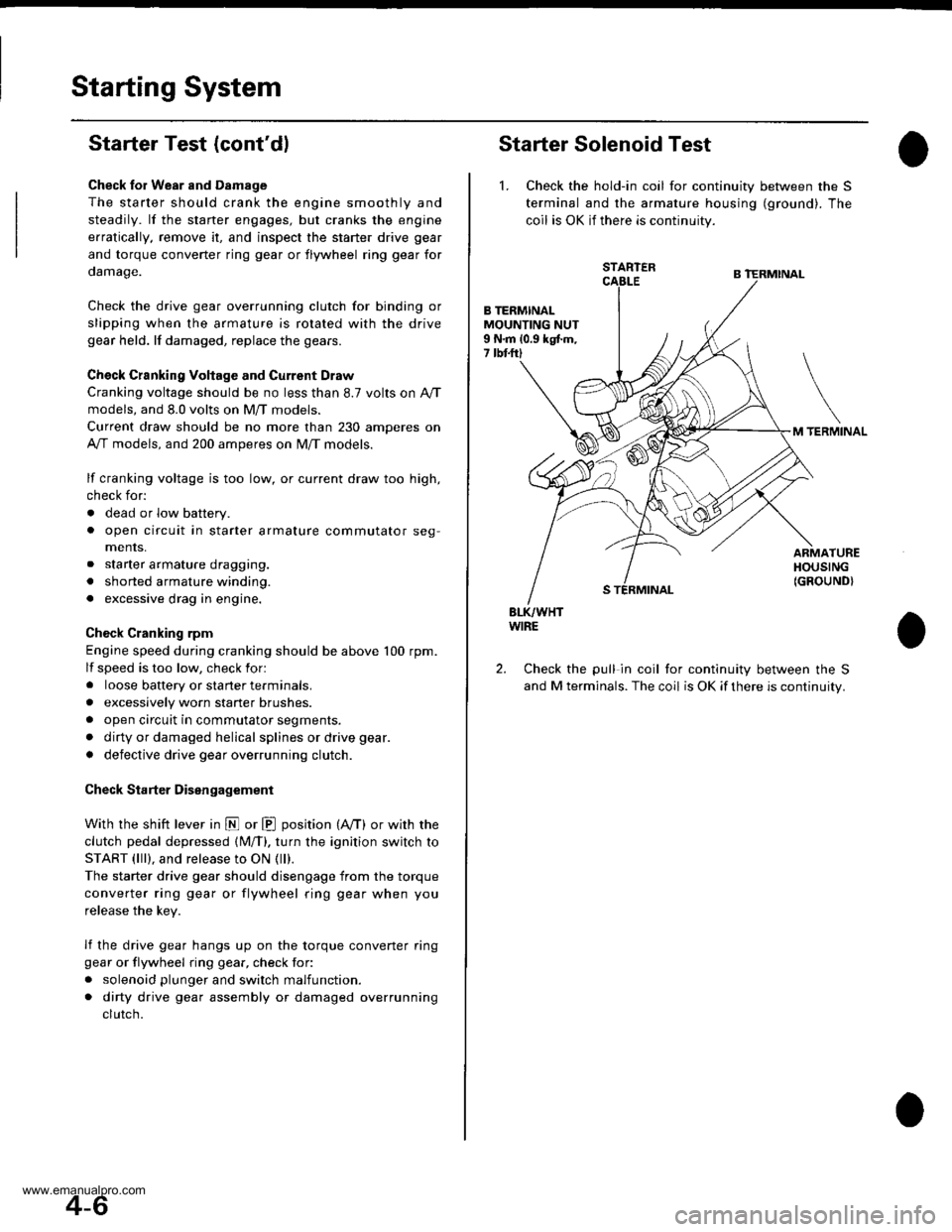
Starter Solenoid Test
1. Check the hold-in coil for continuity between the S
terminal and lhe armature housing (ground). The
coil is OK if there is continuity.
STARTER
B TERMINALMOUNTING NUT9 N.m 10.9 kgtm,7 tbtftl
TERMINAL
ARMATUREHOUSING(GROUND}
BLK/WHTWIRE
Check the pull in coil for continuity between the S
and M terminals. The coil is OK if there is continuity.
2.
4-6
www.emanualpro.com
Page 58 of 1395
Starting System
Starter Overhaul
STARTER SOLENOID
STARTER SOLENOIDTest, page 4 6
OVEBRUNNINGCLUTCH
w
-6^lMOLYBDENUMDISULFIDE
SPRING CLIPReplace.
BBUSH HOLDERTest, page 4-12
ARMATURE HOUSING
ARMATUREInspection and Test. page 4-10
..'...:|@{MOLYBDENUMDISULFIDEBAUSHInsPeclon, page 4-9
ARUSH
GEAR HOUSING
4-A
END COVER
www.emanualpro.com
Page 59 of 1395

Brush Inspection
Measure the brush length. lf it is not within the service
limit, replace the brush (or brush holder assembly).
Brush Lsngth
Standard {Newl: 14.0 - I'1.5 mm (0.55 - 0.57 inl
Servico Limit: 9.0 mm (0.35 in)
NOTE: To seat new brushes after installing them in their
holders. slip a strip of #500 or #600 sandpaper, with the
grit side up, over the commutator and smoothly rotate
the armature. The contact surface of the brushes will be
sanded to the same contour as the commutator.
BRUSH
4-9
2.
1.
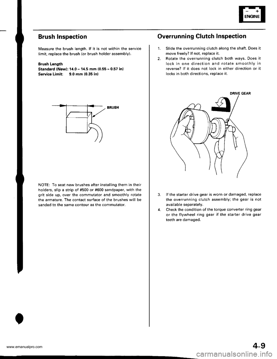
Overrunning Clutch Inspection
Slide the overrunning clutch along the shaft. Does it
move freely? lf not, replace it.
Rotate the overrunning clutch both ways. Does it
lock in one direction and rotate smoothly in
reverse? lf it does not lock in either direction or it
locks in both directions, reDlace it.
3.lf the starter drive gear is worn or damaged, replace
the overrunning clutch assembly; the gear is not
available separately.
Check the condition of the torque converter ring gear
or the flywheel ring gear if the starter drive gear
teeth are damaged.
www.emanualpro.com
Page 89 of 1395

Disconnest the lilP connector from the control unit.
Csvity WireTest condition
R€conn€ct tho 14P connGctor to the control unit.
Test: Desired resultPossible cause it result is not obtained
BRNAr'VHTUnder all conditionsCheck for resistance to groundl
There should be 80 - 120 o.
Faulty actuator solenoid
Poor ground (G202)
An open in the wire1BRNUnder all conditionsCheck for resistance to groundl
There should be 40 - 60 0.
11BRN/BLKUnder all conditionsCheck for resistance to ground:
There should be 70 - 110 O.
2GRY
lgnition switch ON (ll),
main switch ON and
brake pedal depressed,
then released
Check for voltage to ground:
There should be 0 V with the pedal
depressed and battery voltage with
the pedal released.
. Faulty brake switch. An open in the wire
BLKUnder all conditionsCheck for continuity to ground:
There should be continuity.
. Poor ground (G401). An open in the wire
5GRNMHT
Brake pedal depressed,
then released
Check for voltage to ground:
There should be battery voltage with
the pedal depressed, and 0 V with
the pedal released.
Blown No.52 1'15 Alfuse in the
under-hood fuse/relay box
Faulty brake switch
An open in the wire
LT GRN/
RED
Set button pushedCheck for voltage to ground:
There should be battery voltage.Blown No. 52 {'15 A} fuse in the
under-hood fuse/relay box
Faulty horn relay
Faulty sevresume switch
Faulty cable reel
An open in the wire7LT GRN/
BLK
Resume button pushed
10RED/BLU
lgnition switch ON lll)Attach to ground:
Cruise indicator light in the gauge
assembly should come on.
Elown bulbBlown No. 25 (7.5 A) tuse in theunder-dash fuse/relay box
Faulty dimming circuit in the gauge
assembly
An open in the wire
ELU^r'r'HT
lgnitjon switch ON {ll}and main switch ON;
raise the front of the
vehicle, block one wheel
and rotate the other
wheel slowly.
Check for voltage between the
ELUA/VHT @ and BLK O terminalsl
There should be 0 - 5 V or more-0 - 5 V or more repeatedly.
Faulty vehicle speed sensor (VSS)
An open in the wire
r3LT GRN
lgnition switch ON {ll}and main switch ONCheck for voltage to ground:
There should be battery voltage.
Blown No. 14 (7.5 A) fuse in theunder-dash fuse/relay box
Faulty main switch
An open in the wire
l4PNK
A'/T: Shift lever in E, EotE
lvl/T: Clutch pedal
releaseo
Check for continuity to ground:
There should be continuity.NOTE: There should be no continu-
ity when the shift lever is in otherpositions or when the clutch pedal is
oepresseo.
Faulty A/f gear position switch 1A,/TlFaulty or misadjusted clutch switch
fi{/r)Poor ground (G101)
An open in the wire
BLU
Start tho engine. turnthe main switch ON, anddrive the vehicle over 25
mph (40 km/h)with the
crurse control set
Check for voltage to ground:
There should be approx.5 V
. Faulty cruise control unit. Shod to ground
*: '98 - 00 models with Automatic Transmission.
4-39
www.emanualpro.com
Page 148 of 1395
Special Toolstl
Ref, No. I Tool NumborDescriptionOty Page Reterence
o
@
@/6
@
o
@
@
@
@
07GAF - PH60300
07HAF - P120102
07LAB - PV00100
07LAD - PT30101
07LAF - PR30100
07948 - S800101
07749 - 0010000
07973 - PE00310
07973 - PE00320
07973 - 6570500
07973 - 6570600
Piston Pin Base lnsert
Piston Base Head
Ring Gear Holder
Seal Driver
Pilot Collar
Seal Driver Attachment. 76 x 80 mm
Driver
Piston Pin Driver Shaft
Piston Pin Driver Head
Piston Base
Piston Base Spring
,l
1
I
I
1
1
1
1
1
1
1
7-14,15
1-'t4,15
1-5
1-23
7-14,15
7-'t9,24
7 -'t9, 24
1-14,15
7-14,15
7-'t4,15
7-14,15
eEEg
o
a@
0
o@
7-2
www.emanualpro.com
Page 151 of 1395
Flywheel and Drive Plate
Replacement
Manual Transmission:
Remove the eight flywheel bolts, then separate the fly-
wheel from the crankshaft flange. After installation, tight-
en the bolts in the sequence shown.
ENGINEBLOCK
12 x 1.0 mm103 N.m 110.5 kgf.m,76 lbf.ft)
Automatic Transmission:
Remove the eight drive plate bolts, then separate the
drive plate from the crankshaft flange. After installation,
tighten the bolts in the sequence shown.
RING GEARInspect ring gearteeth for wear or damage,
RI G GEAR HOTDER07LAB - PV001|X)
12 x 1.0 mm7a N.m(7.5 kgt.m,5a lbf.ftl
/ AzXi{'jA\Ao
7-5,
www.emanualpro.com