Page 351 of 1395
ldle Control System
System Description
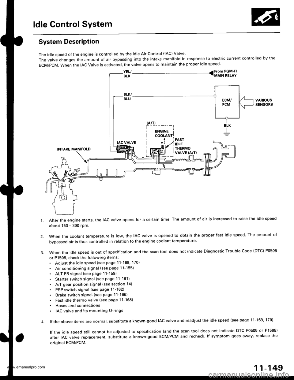
The idle speed of the engjne is controlled by the ldle Air Control (lAC) Valve'
The valve changes the amount of air bypassing into the intake manifold in response to electric current controlled by the
ECM/PCM. When the lAc valve is activated, the valve opens to maintain the proper idle speed.
YEL/ From PGM'FI
BLK TMAIN RELAY
VARIOUSSENSORS
4.
IAC VALVE
INTAKE MANIFOLD
After the engine starts, the IAC valve opens for a certain time. The amount of air is increased to raise the idle speed
about 150 - 300 rpm.
when the cootant temperature ts row, the lAc valve is opened to obtain the proper fast idle speed The amount o{
bvoassed air is thus controlled in relation to the engine coolant temperature
When the idle speed is out o{ specification and the scan tool does not indicate Diagnostic Trouble Code (DTC) P0505
or P1508, check the following items:
. Adjust the idle speed (see page 11-169, 170)
. Air conditioning signal (seepagell-1551
. ALT FR signal (see page 1l-159)
. Starter switch signal (see page 11-16'1)
. A,/T gear position signal (see section 14)
. PSP switch signal (seepagell-162)
. Brake switch signal (see page 11-165)
. Fast idlethermovalve (see page'11 168)
. Hoses and connecttons. IAC valve and its mounting O-rings
lf the above items are normat, suDslitute a known-good IAC valve and readjust the idle speed {see page 11-169, 170)
lf the idle speed still cannot be adjusted to specification (and the scan tool does not indicate DTC P0505 or Pl508)
after IAC valve reolacement, substitute a known-good ECM/PCM and recheck lf symptom goes away' replace the
original ECM/PCM.
11-149
www.emanualpro.com
Page 429 of 1395
Special Tools
Rel. No. I Tool NumberDescriptionOty Page Reference
a
IA
@
!c,
Lo,
OTJAF - PM70,I1A
07NAF - PR30l00
07LAB - PV00100 or
07924 - PD20003
07746 0010100
07749 - 0010000
07936 - 3710100
Clutch Alignment Disc
Clutch Alignment Shaft
Ring Gear Holder
Attachment, 32 x 35 mm
Driver
Ha nd le
1 | t2-7
1 12-7 , A, '�t0, 11
1 12-7 ,9, 10, 1'l
I1 I 12-10
1 12-10
1 12-7 , a, 10, 11
b)
2-2
www.emanualpro.com
Page 434 of 1395
Pressure Plate
Removal/lnspection
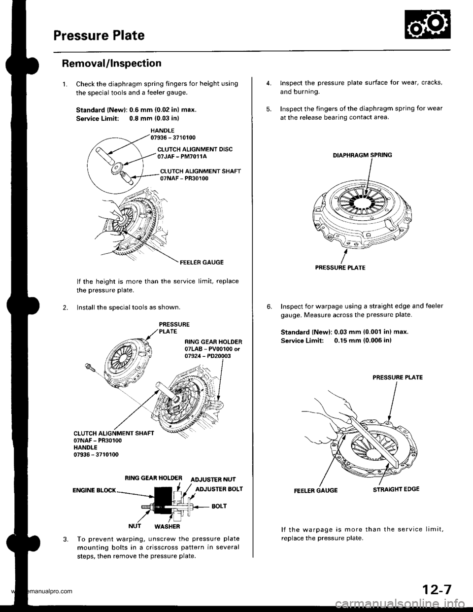
1.Check the diaphragm spring fingers for height using
the special tools and a feeler gauge.
Standard lNewl: 0.6 mm {0.02 in) max.
Service Limit: 0.8 mm (0.03 in)
HANDLE07936 - 3710100
CLUTCH ALIGNMENT DISCOTJAF - PM7O11A
CI.UTCH ALIGNMENT SHAFT07NAF - PR30100
FEELER GAUGE
lf the height is more than
the pressure Plate.
the service limit, replace
2. lnstall the sDeciallools as shown.
RING GEAR HOLDER ADJUSTER NUT
ENGINE BLOCKADJUSTER BOLT
BOLT
NUT WASHER
To prevent warping, unscrew the pressure plate
mounting bolts in a crisscross pattern in several
steps. then remove the pressure plate.
4. Inspect the pressure plate surface for wear, cracks,
and burning.
5. Inspect the fingers of the diaphragm spring for wear
at the release bearing contact area.
Inspect for warpage using a straight edge and feeler
gauge. Measure across the pressure plate.
Standard lNew): 0.03 mm 10.001 in) max.
Service Limit: 0.15 mm (0.006 inl
6.
FEELER GAUGE
lf the warpage is more than the service limit,
replace the pressure plate.
PRESSURE PLATE
PRESSURE PLATE
12-7
www.emanualpro.com
Page 436 of 1395
Flywheel
Inspection
2.
3.
Llnspect the ring gear teeth for wear and damage.
Inspect the clutch disc mating surface on the fly-
wheel for wear, cracks, and burning
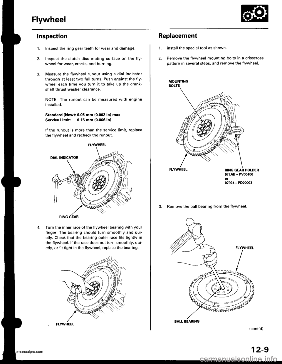
Measure the flywheel runout using a dial indicator
through at least two full turns. Push against the fly-
wheel each time you turn it to take up the crank-
shaft thrust washer clearance.
NOTE: The runout can be measured with engine
installed.
Standard (Newl: 0.05 mm (0.002 in) max.
Service Limit: 0.15 mm {0.006 inl
lf the runout is more than the service limit, replace
the flywheel and recheck the runout
Turn the inner race ot the flywheel bearing with your
finger. The bearing should turn smoothly and qui-
etly. Check that the bearing outer race fits tightly in
the tlywheel. lf the race does not turn smoothly, qui-
etly, or fit tight in the flywheel, replace the bearing.
FLYWHEEL
RING GEAR
FLYWHEEL
L
2.
Replacement
Installthe special tool as shown.
Remove the flywheel mounting bolts in a crisscross
pattern in several steps, and remove the flywheel.
MOUNNNGBOLTS
FLYWHEEL
(cont'd)
12-9
RING GEAR HOLDER07LAB - PV00r00ol07924 - PD20003
3. Remove the ball bearing from the flywheel.
BALL BEARING
www.emanualpro.com
Page 437 of 1395
FlywheelClutch Disc, Pressure Plate
Replacement (cont'dl
Drive the new bearing
specialtools.
HANOLE DRIVER07749-
ATTACHMET{T-32x35mm07746 -O010100
FLYWHECI-
Align the hole in the flywheel with the crankshaft
dowel pin, and install the flywheel. Install the
mounting bolts finger-tight.
Install the special tool, then torque the flywheel
mounting bolts in a crisscross pattern in several
steps as shown.
Torque:12 x 1.0 mmr03 N.m (10.5 kgl.ln,75.9 tbtftl
into the flywheel using the
12-10
Installation
1. Install the ring gear holder.
CLUTCH ALIGNMENT SHAFT07NAF - PR30100
CLUTCH DISC
RING GEAR HOLDER07LAB _ pvoot(x) or07924 _ PD20003
Apply grease to the spline of the clutch disc, then
install the clutch disc using the special tools.
NOTE: Use only Super High Temp Urea Grease(P/N 08798 - 9002).
lnstall the pressure plate.
PRESSURE PLATE
www.emanualpro.com
Page 440 of 1395
Manual Transmission
Diff€rential
lndex ...................... ......... 13-38
Backlash Inspestion ..,....,.,.....................,......, 13-38
Final Driven Gear Replacement .................... 13-39
Tapered Roller BearingReplacement ............. 13-39
Bearing Outer Race Replacement ......,.,........ 13-i10
Tapered Roller Bearing PreloadAdiustment ............... 13-il1
Oil Seal Reolacement .................................... 13-/l:}
Transfer Assembly
lllustrated Index ............. 13-il4
Inspection ..,....,.,......,...... 13-46
Disassembly ................... 13-47
Transfer Drive Gear BearingReplacement ...,..................,....................... 13-ilg
Transfer Driven Gear Shaft BearingReplacement .............................................. 13-ilg
Transfer Shaft Disassembly/Reassembly .............. 13-50
Transler Cover A Bearing Outer RaceRep1acement.........,.,.,..........,....,...,.........,., 13-50
Transter Housing Bearing Outer RaceReD1acement.............................................. 13-51
Reassembly ..-............,... 13-52
Mainshaft Bearing/Oil Seal
Beplacement .................. 13-62
Countershaft Bearing
Replacement .,,.,.,., ..,...... 13-63
Mainshaft Thrust Clearance
Adiustment .................... 13-6,1
Transmission Assembly
Reassembly .,.,.,.,..,.,....,., 13-67
fnstaffation .,.,.............,... 13-72
Gearshift Mechanism
Overhaul ................ .........13-17
www.emanualpro.com
Page 443 of 1395
Transfer Assembly
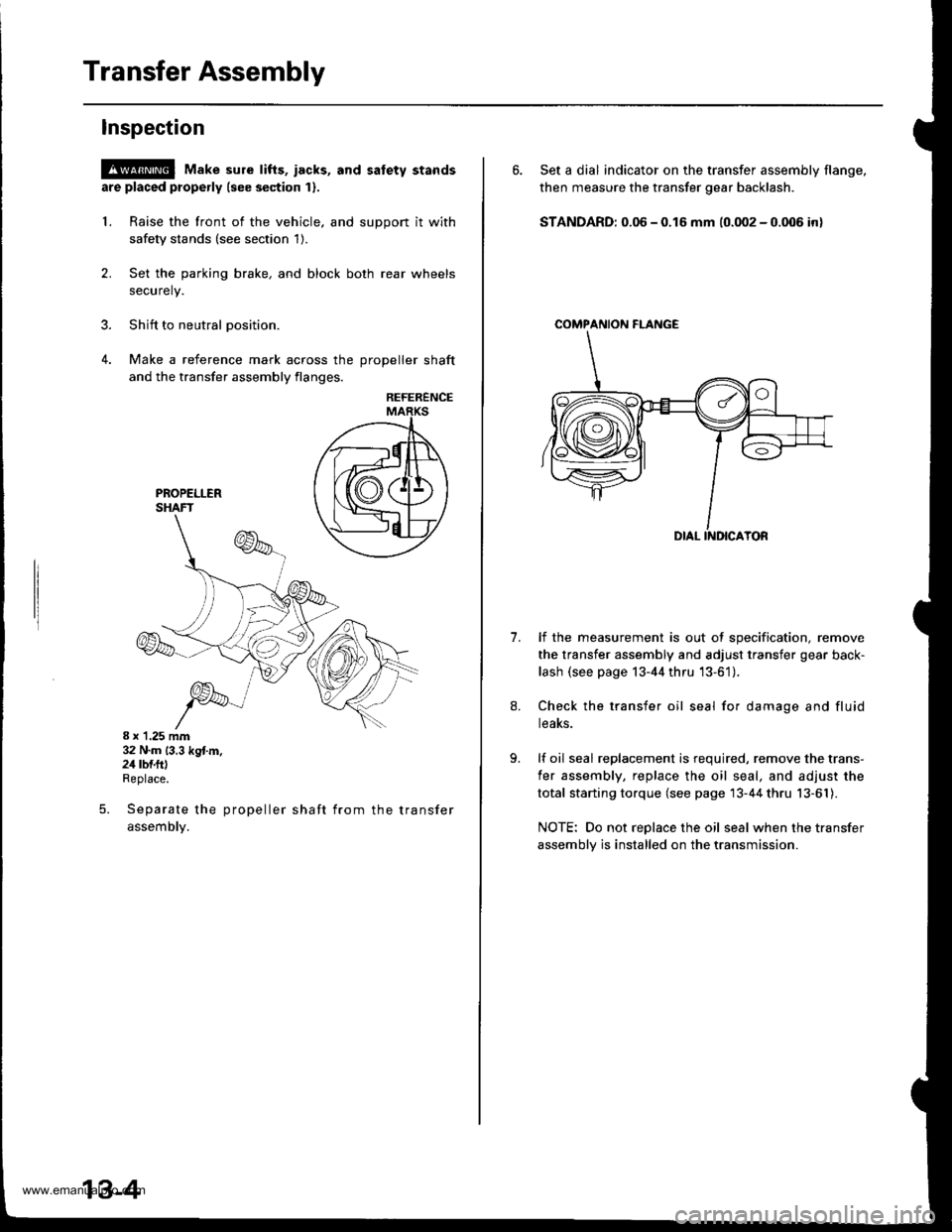
lnspection
@ Make sure tifts, iacks, and satety stands
are placed properly (see section 1).
L Raise the front of the vehicle, and support it with
safety stands (see section 1).
2. Set the parking brake, and block both rear wheels
securely.
3. Shift to neutral oosition.
4. Make a reference mark across the DroDeller shaft
and the transfer assembly flanges,
REFERENCE
8 x 1.25 mm32 N.m (3.3 kg{.m.24 rbf.ftlReplace.
Separate the propeller shaft from the transfer
assemDty.
5.
13-4
6. Set a dial indicator on the transfer assembly flange,
then measure the transfer gear backlash.
STANDARD: 0.06 - 0.16 mm (0.002 - 0.006 in)
COMPAf{ION FI-ANGE
1.lf the measurement is out of specification, remove
the transfer assembly and adjust transfer gear back-
lash (see page 13-44 thru '13-61).
Check the transfer oil seal for damage and fluid
teaKs.
lf oil seal replacement is required, remove the trans-
fer assembly, replace the oil seal, and adjust the
total starting torque (see page 13-44 thru 13-61).
NOTE: Do not replace the oil seal when the transfer
assembly is installed on the transmission.
www.emanualpro.com
Page 451 of 1395
Transmission Assembly
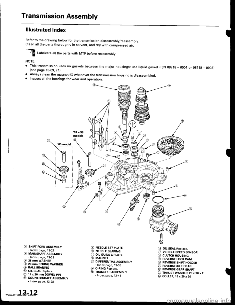
lllustrated Index
Refer to the drawing below for the transmission disassembly/reassembly.Clean all the pans thoroughly in solvent, and drv with comoressed air.
I LuUri""r" utt the parts with MTF before reassembly.
NOTE:
t This transmission uses no gaskets between the major housings; use liquid gasket (p/N 0g718 - 0001 or oE7l8 - 0003)(see page 13-69, 71).. Always clean the magnet @ whenever the transmissjon housing is disassembled.. Inspect all the bearings for wear and operation.
C) sHrFr FoRK ASSEMBLY.Index page, l3-21(a MAINSHAFT ASSEMBLY.Index page, 13-23(9 28 mm WASHER€) 28 mm SPRTNG WASHERO BALL BEARINGa6) OIL SEAL ReDlace.(D 14 x 20 mm DOWEL ptN
G) couNTERSHAFT ASSEMBLY.lndex page, 13-28
NEEDLE SET PLATENEEDLE BEARINGOIL GUIOE C PLATEMAGNETDIFFERENTIAL ASSEMBLY.lndex page, 13-38O-nlNG Beplace.TRANSFER ASSEMBLY.Index page, '13,44
OIL SEAL Replace.VEHICLE SPEED SENSORCLUTCH HOUSINGREVERSE LOCK CAMREVEESE SHIFT HOLDERREVERSE IDLE GEARREVERSE GEAR SHAFTTHRUST WASHER,20 x 36 x 2COLLER, 15 x 20 x 20
aol
@o@@
(D
i9
@@@(9
@@@e3@
13-12
www.emanualpro.com