Page 725 of 1395
One-way Glutch
Disassembly/lnspection/Reassem bly
1. Separate countershaft 1st gear from the park gear
by turning the park gear in the direction shown.
PARK GEAR
2. Remove the one-way clutch by prying it up with the
tip of a screwdriver.
COUNTERSHAFT IST GEARONE.WAY CLUTCHInstall in this direction.
ONE.WAY CLUTCH
lST GEAR
COUNTERSHAFT lST GEAR
SCREWDRIVER
14-209
3. Inspect the oarts as follows;
PARK GEARInspect Ior wearand sconng.
ONE.WAY CLUTCHInspect for damageand taulty movement,
4.
lST GEARInspect for wearand scortng.
After the parts are assembled, hold countershaft lstgear. and turn the park gear in the direction shown
to be sure it turns freely. Also make sure the park
gear does not turn in the opposite direction.
COUNTERSHAFT ,IST GEAR
www.emanualpro.com
Page 736 of 1395
Clutch
Installthe snap ring.
Reassembly (cont'd)
7.
S AP RIIG
8. Remove the special tools.
9, Install the disc spring in the direction shown.
1ST, 2ND, 4TH, lST-HOLD CLUTCH:
3RD CLUTCH:
Dlsc sPRrrtc
CIUTCH ORUM
otsc sPfitl{c
14-220
10.Soak the clutch discs thoroughly in ATF for a mini_mum of 30 minutes. Before installing the platesand discs, make sure the inside of the clutch drumis free of din or other foreign matter
Starting with a clutch plate, alternatelv install theclutch plates and discs. Install the clutch end platewith its flat side toward the disc.
CLUTCH EI{D PI.ATEInstall in this directior.
CLUTCHCLUTCH EI{D PLATE
12. Install the snap ring.
SCREWDRIVER
't1.
www.emanualpro.com
Page 738 of 1395
Differential
lllustrated Index
'lWD:
SET RING, 80 mmSelective part
10 x 1.0 mm103 N.m (10.5 kgt.m,?5.9 tbtftl
FINAL ORIVEN GEARlnspect for excessive wear,Install in this direction.
BALL BEARINGInspect for rough
DIFFERENTIAI.CARRIERlnspect for cracks.
TRANSFER SHAETDNlvE GEARInspect for excessive
SPEEDOMETERDRIVE GEARInstall in thisdirection.
SNAP RINGInstall in thisdirection.
BALL BEARINGInspect for rough movement,
14-222
2WDl
SET nlNG, 80 mmSel6ctive part
A,U
,gBc
10 x 1.0 mm103 N.m {10.5 kg[.m,75.9 tbt.ftlLeft-hand threads
FINAL ORIVEN GEARInspect for excessive wear,Install in thls direction.
BALL BEABINGInspect for rough
DIFFERENTIAI.CARRIERInspect for cracks.
ROLLER,5 x 10 mm
SPEEDOMETERDRIVE GEARInstall in thisdirection.
SNAP RINGInstall in thisdirection.
BALL BEARING
www.emanualpro.com
Page 739 of 1395
Backlash Inspection
Place the differential assembly on V-blocks.
lnstall the driveshaft and intermediate shaft on the
differential assemblY.
Check the backlash of both pinion gears.
STANDARD: 0.05 - 0.15 mm (0.002 - 0.006 in)
OIFFEBENNAL ASSEMBLY
It the backlash is out of standard, replace the difter-
ential carrier.
1.
DIAL INDICATOR
Bearing Replacement
NOTE: Check bearings for wear and rough movement.
lf bearings are OK, removal is not required.
1. Remove the bearings using a bearing puller.
BEARING PULLER(Commercially available)
lnstall new
snown.
bearings using the sPecial tool
PRESS
14-223
www.emanualpro.com
Page 740 of 1395

Differential
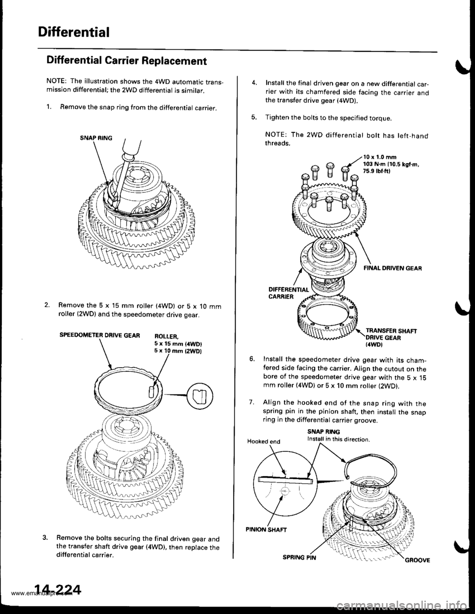
Differential Carrier Replacement
NOTE: The illustration shows the 4WD automatic trans-mission differential; the 2WD differential is similar.
1. Remove the snap ring from the differential carrier.
Remove the 5 x 15 mm roller (4WD) or 5 x 10 mmroller (2WDl and the speedometer drive gear.
SPEEDOMETER DRIVE GEAR RoI I FP
Remove the bolts securing the final driven gear andthe transfer shaft drive gear (4WD), then replace thedifferential carrier.
5 x 15 mm (/tWD)5 x 10 mm {2WDl
14-224
SPRING PINGROOVE
Install the final driven gear on a new differential car-rier with its chamfered side facing the carrier andthe transfer drive gear (4WD),
Tighten the bolts to the specified torque.
NOTE: The 2WD differentiat bolt has left-handthreads,
10 x 1.0 mm103 N.m 110.5 kd.m,7s.9 rbr.ft)
7.
FINAL DRIVEN GEAR
TRANSFER SHAFT
Install the speedometer drive gear with its cham-fered side facing the carrier. Align the cutout on thebore of the speedometer drive gear with the 5 x 15mm roller (4WD) or 5 x 10 mm roller (2WD).
Align the hooked end of the snap ring with thespring pin in the pinion shaft. then install the snaoring in the differential carrier groove
SNAP RINGInstall in this direction.Hooked end
PINION SHAFT
{4WDl
www.emanualpro.com
Page 741 of 1395
Oil Seal Replacement
1. Remove the oil seal from the transmission housing.
OIL SEALReplace.
Remove the oil seal from the torque converter
housing.
OIL SEALReplace.TOROUE CONVERTERHOUSING
-.].
3. lnstall the oil seal in the transmission housing using
the special tools as shown.
DRIVER077a9 - 0010000
ATTACHMEMT079r? - slx[ax)
4.Install the oil seal in the torque converter housing
using the specialtools as shown.
14-225
www.emanualpro.com
Page 744 of 1395

Transmission Housing Bearings
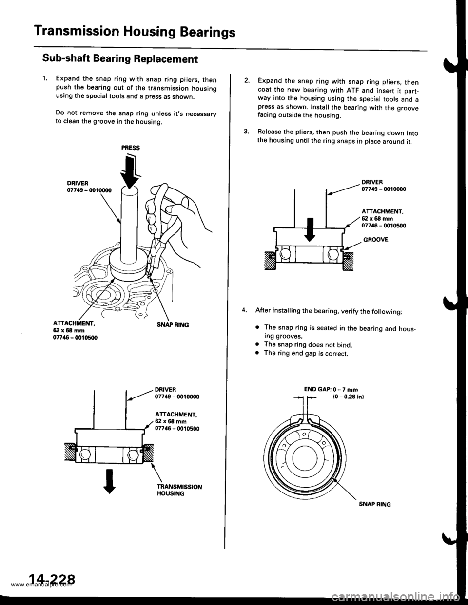
Sub-shaft Bearing Replacement
1. Expand the snap ring with snap ring pliers, thenpush the bearing out of the transmission housingusing the special tools and a press as shown.
Do not remove the snap ring unless it,s necessaryto clean the groove in the housing.
ATTACHMEI{T,5:l x 68 mm07r{5 - @10500
SNAP RI]TG
DRIVER07749 - tDl(xx)o
ATTACHMENT,6:l x 68 mm077a6 - (X,r0500
14-228
SNAP RING
Expand the snap ring with snap ring pliers, thencoat the new bearing with ATF and insert it part-way into the housing using the special tools and apress as shown. lnstall the bearing with the groovefacing outside the housing.
Release the pliers, then push the bearing down intothe housing untilthe ring snaps in place around it.
DRIVER07743 - 0010mo
ATTACHMENT,{i:l x 68 mm07746 - 0010500
GROOVE
After installing the bearing, verify the following:
. The snap rjng is seated in the bearing and hous_ing grooves.
. The snap ring does not bind.. The ring end gap is correct,
ENDGAP:0-7mm
www.emanualpro.com
Page 746 of 1395
Torque Gonverter Housing
BearingsGontrol Lever Assembly
Countershaft Bearing Replacement
1. Remove the countershaft bearing using the specialtool.
SLIOE HAMMER,3la" -16(Commercially available)
ADJUSTABLE BEARINGPULLER,25 - 40 mm07736 - A0100OB ol07736 - A01m0A
Install the ATF guide ptate.
Install a new countershaft
converter housing.
COUNTERSHAFTBEARING
bearing in the torque
DRIVER077i19 - 001m00
14-230
ATF GUIDE PLATE
Replacement
Check the condition and movement of the control leverassembly, lf the control lever assembly binds or doesnot move smoothly. replace it.
1. Remove the 6 x 1.0 mm bolt and lock washer.
2. Remove the change shaft trom the torque converterhousing.
3. Remove the control lever assembly from the controlshaft.
4. Install the new control lever assembly in the reverseorder of disassembly, until it bottoms in the torqueconverter housing.
LOCK WASHERReplace.
www.emanualpro.com