Page 797 of 1395

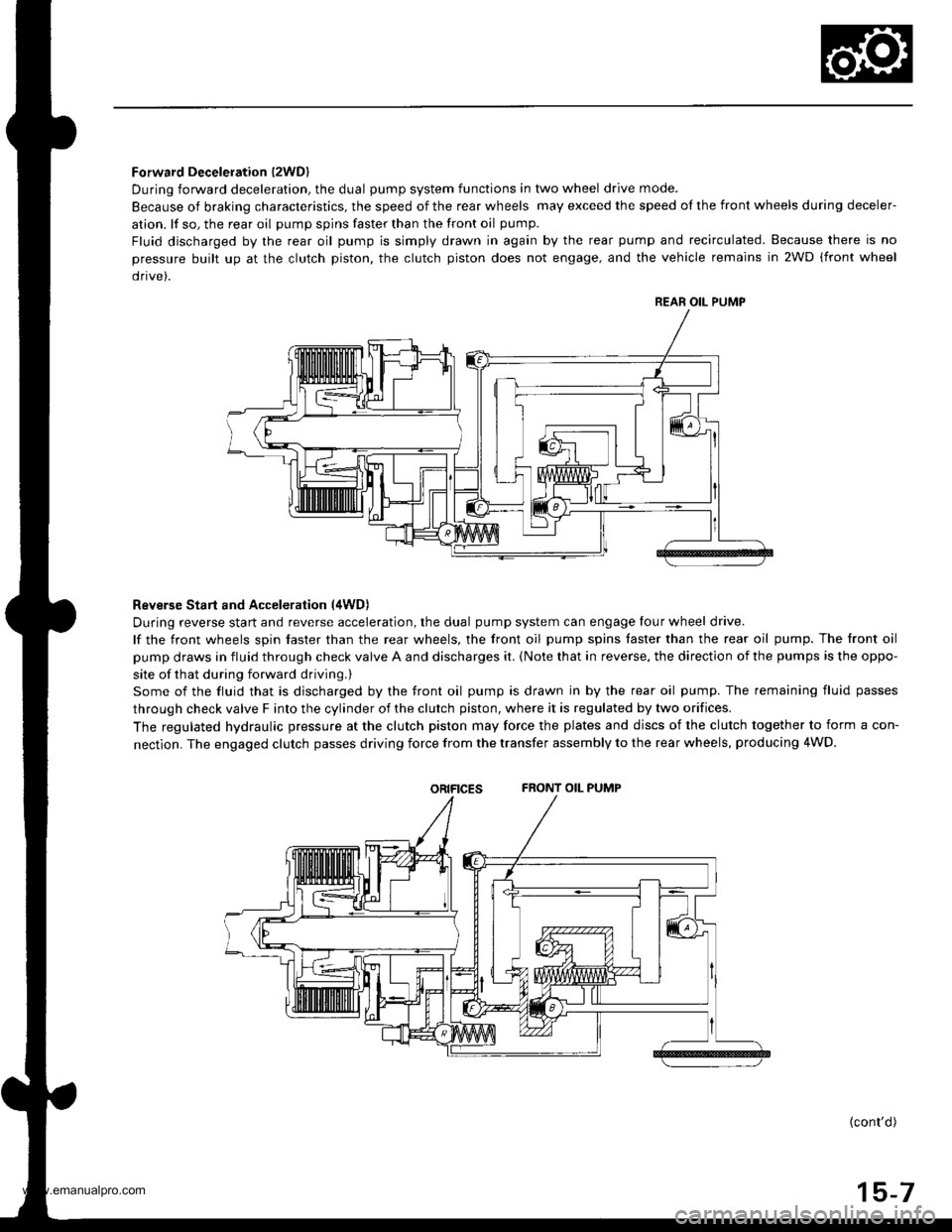
Forward Deceleration l2WDl
During forward deceleration, the dual pump system functions in two wheel drive mode.
Because of braking characteristics, the speed of the rear wheels may exceed the speed ol the front wheels during deceler-
ation. lf so, the rear oil pump spins faster than the front oil pump.
Fluid discharged by the rear oil pump is simply drawn in again by the rear pump and recirculated. Because there is no
pressure built up at the clutch piston. the clutch piston does not engage, and the vehicle remains in 2WD (front wheel
drive).
Reverse Start and Acceleration (4WD)
During reverse start and reverse acceleration, the dual pump system can engage four wheel drive.
lf the front wheels spin faster than the rear wheels, the front oil pump spins faster than the rear oil pump. The front oil
pump draws in fluid through check valve A and discharges it. {Note that in reverse, the direction of the pumps is the oppo-
site of that during forward driving.)
Some of the fluid that is discharged by the front oil pump is drawn in by the rear oil pump. The remaining fluid passes
through check valve F into the cylinder of the clutch piston, where it is regulated by two orifices.
The regulated hydraulic pressure at the clutch piston may force the plates and discs of the clutch together to form a con-
nectlon. The engaged clutch passes driving force from the transfer assembly to the rear wheels, producing 4WD.
oRtFtcEsFRONT OIL PUMP
{cont'd)
15-7
REAR OIL PUMP
www.emanualpro.com
Page 798 of 1395

Description
Hydraulic Flow (cont'dl
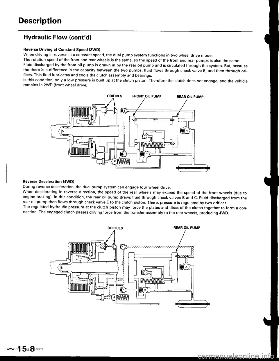
Reverse Driving at Constant Speed l2WD)when driving in reverse at a constant speed, the dual pump system functions in two wheel drive mode.The rotation speed of the front and rear wheels is the same, so the speed of the front and rear pumps is also the same,Fluid discharged by the front oil pump is drawn in by the rear oil pump and is circulated through the system. But, becausethe there is a difference in the capacity between the two pumps, fluid flows through check valve E, and then through ori-Iices. This fluid lubricates and cools the clutch assembly and bearings.ls this condition, only a low pressure is built up at the clutch piston. Therefore the clutch does not engage, and the vehicleremains in 2WD (front wheel drive).
Reverse Deceleration l/tWDl
During reverse deceleration, the dual pump system can engage four wheel drive.When decelerating in reverse direction, the speed of the rear wheels may exceed the speed of the front wheels (due toengine braking). In this condition, the rear oil pump draws fluid through check valves B and C. Fluid discharged from therear oil pump then flows through check valve E to the clutch piston. There, pressure is regulated by two orifices.The regulated hydraulic pressure at the clutch piston may force the plates and discs of the clutch together to form a con,nection. The engaged clutch passes driving force from the transfer assembly to the rear wheels, producing 4WD.
oRtFtcEsREAR OIL PUMP
www.emanualpro.com
Page 799 of 1395
Thermal Switch Operation l2WD)
During 4WD operation, pressure-regulated fluid is in contact with the clutch piston and the thermal switch.
lf the temperature of the fluid in the differential goes too high, the thermal switch pushes open the relief valve R. This
causes the pressure in the clutch piston to drop, and 4WD mode is disengaged.
THERMAL SWITCHRELIEF VALVE
Reliet Valve Operation
When the fluid pressure goes higher than the relief valve spring force, check valve R opens. Pressure applied at the clutch
piston is held constant. This feature adds stability by preventing the rear wheel drive system from experiencing excessive
to rque.
RELIEF VALVE
15-9
www.emanualpro.com
Page 803 of 1395
Rear Differential AssemblY
Troubleshooting
Most problems in the unit are to be diagnosed by identifying noises from the gears or bear'ngs'
care should be taken during diagnosis not to confuse differential noises with those from other drivetra'n components'
SymptomProbable CauseRemedy
Will not go into 4WD mode. Fluid level too low
. Incorrect fluid type
. Add fluid. Replace
Will not return to 2WD modeIncorrect fluid typeDrain and fill the differential
Gear or bearing noisesFluid level too low
Incorrect fluid type
Damaged or chipped gears
Add fluid
Drain and fill the differential
Replace the differential carrier
assemory
Overheating. Fluid leveltoo low
. Incorrect fluid type
. Add fluid. Drain and fill the differential
Fluid leakFluid level too high
Clogged breather hose
Worn or damaged oil seal
Damaged sealing washer
Loose mounting bolts or inade-
quate sealing
Lower to proper level
Clean or replace
Replace
Replace
Recheck torque or aPPIY sealant
15-13
www.emanualpro.com
Page 805 of 1395
Rear Differential Assembly
lllustrated Index
O.RINGReplace.
6xl.0m12 N.m (1.2 kgf m,8.7 lbt'ftl
BACK-UP RING
COMPANION FLANGE
CLUTCH HUB/PLATES/DISCS
DIFFERENNAL CLUTCHASSEMBLY
DOWEL PINS
OIL PUMP DRIVESHAFT
LOCKNUT, 24 mmReplace.118 N.m (12.0 kgtm.87 rbt ft)
OIL SEALReplace.
PRESSURE PLATE
THBUST NEEDLEAEARING""t",at\(
'd'
CLUTCH GUIDE
OIL PUMPPIN
e
MAGNET
6x1.0mm12 N.m 11.2 kgt'm,8.7 lbf'ft|
OIL STRAINER
15-15
www.emanualpro.com
Page 807 of 1395

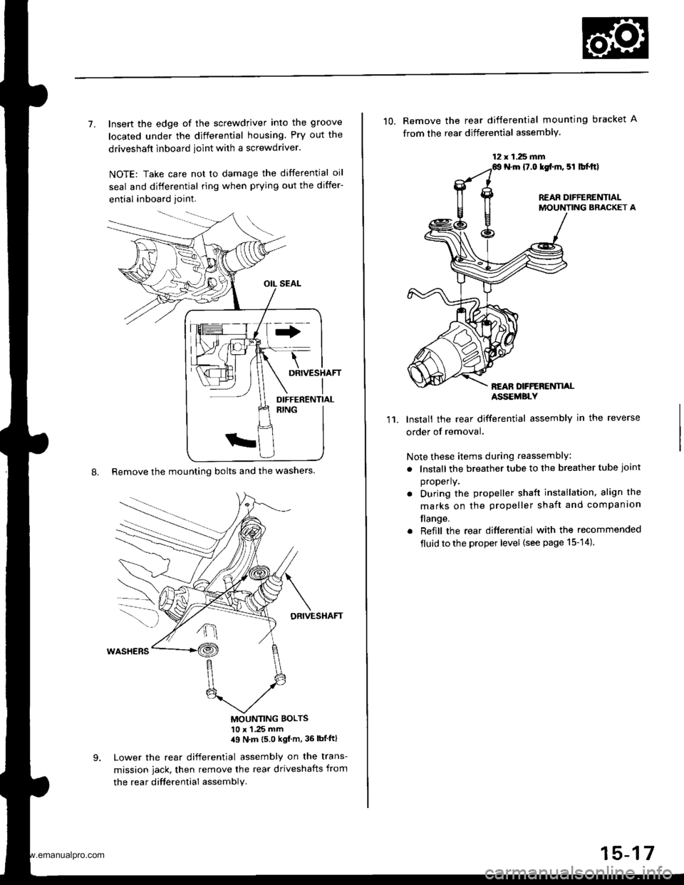
7. Insert the edge of the screwdriver into the groove
located under the differential housing Pry out the
driveshaft inboard ioint with a screwdraver.
NOTE: Take care not to damage the differential oil
seal and differential ring when prying out the differ-
ential inboard joint.
8. Remove the mounting bolts and the washers.
DRIVESHAFT
MOUNTING BOLTS'10 x 1 .25 mm,19 N'm (5 0 kgf m, 36 lbtftl
Lower the rear differential assembly on the trans-
mission jack, then remove the rear driveshafts from
the rea r difterential assembly.
DIFFERENTIAL
12 x 1.25 fifi
10. Remove the rear difterential mounting bracket A
from the rear differential assembly.
N.m {7.0 lgf.m. 5l lbl.tt)
REAR DIFFERENTIALMOUNTING BRACKET A
REAN DFFERENTI,ALASSEMBLY
11.Install the rear differential assembly in the reverse
order of removal.
Note these items during reassembly
. lnstall the breather tube to the breather tube joint
properly.
. During the propeller shaft installation, align the
marks on the propeller shaft and companion
flange.
. Reiill the rear differential with the recommended
fluid to the proper level {see page 15-14).
15-17
www.emanualpro.com
Page 812 of 1395
Rear Differential Assembly
Disassembly (cont'dl
9. Remove the shim and the clutch quide.
d"HIM'30mm
CLUTCH GUIDE
Remove the clutch hub/plates/discs and the pressure
prare.
10.
CLUTCH HUB/PLATES/OISCS
k
ffi-:*
_zz PRESSURE PLArE
@-
15-22
11. Remove the thrust needle bearing and the oil pump
driveshaft.
Remove the oil pump body assembly, the oil pump
pin, the magnet, and the oil strainer.
OIL PUMP BODY ASSEMBLY
MAGNET
OIL PUMP PIN
12.
OIL STRAINERInspect for damageor clogging.
www.emanualpro.com
Page 813 of 1395
Reassembly
1. Apply CVT fluid to the rubber of the oil strainer, then
install the oil strainer, the magnet, and the oil pump
pin to the differential carrier.
OIL PUMP PIN
DIFFERE]TTIAL CARRIERASSEMBLY
Align the oil pump pin with the groove of the rear oil
pump in the pump body assembly, then install the oil
pump body assembly to the differential carrier assem-
oty.
-n
CWfluid
2.
MAGNET
OIL PUMP BODY ASSEMBLY
3. Tighten the oil pump body assembly mounting
bolts.
4. Install the oil pump driveshaft by aligning the pro-
jection of the oil pump driveshaft with the groove of
the front oil pump in the oil pump body assembly.
lnstall in this direction.
Projection
6x1.0mm12 N.m 11.2 kg{.m,8.7 lbl.ft}
Install the thrust needle bearing.
Install the pressure plate assembly by aligning the
projection of the pressure plate with the groove of
the oil pump driveshaft.
5.
OIL PUMPDRIVESHAFT
(cont'd )
15-23
THRUST NEEDLE BEABING
PRESSURE PLATE
www.emanualpro.com