1999 HONDA CR-V Drive
[x] Cancel search: DrivePage 758 of 1395
Transfer Assembly
Reassembly (cont'd)
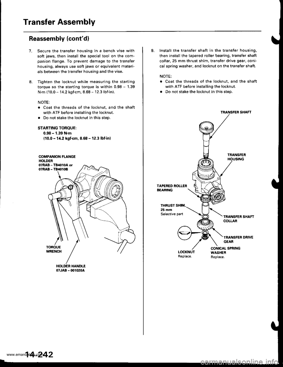
7.Secure the transfer housing in a bench vise with
soft jaws, then install the special tool on the com-
panion flange. To prevent damage to the transfer
housing, always use soft jaws or equivalent materi-
als between the transfer housing and the vise.
Tighten the locknut while measuring the starting
torque so the starting torque is within 0.98 - '1.39
N.m (10.0 - 14.2 kgf.cm, 8.68 - 12.3 lbnin).
NOTE:
Coat the threads of the locknut, and the shaft
with ATF before installing the locknut.
Do not stake the locknut in this step.
STARTING TOROUE:
0.98 - 1.39 N.m
{10.0 - 14.2 kgrf.cm,8.68 - 12.3 lbf'inl
COMPANION FLANGEHOLDER
07JAB - @1020A
14-242
9. Install the transfer shaft in the transfer housing,
then install the tapered roller bearing, transfer shaft
collar.25 mm thrust shim, transfer drive gear, coni-
cal spring washer, and locknut on the transfer shaft.
NOTE:
. Coat the threads of the locknut. and the shaft
with ATF before installing the locknut.
. Do not stake the locknut in this step.
TRANSFER
THRUST SXIM,25 mmSelective pan
TRANSFER DRIVEGEAR
CONICAL SPRINGWASHERReplace.
www.emanualpro.com
Page 760 of 1395
Transfer Assembly
18.
Reassembly (cont'dl
16. Apply Prussian Blue to both sides of the transfergear teeth lightly and evenly.
17.Rotate the companion flange in both directions until
the transfer gear rotates one full turn in both direc-
tions.
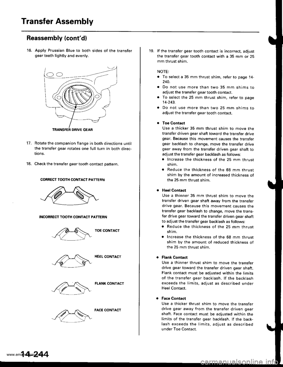
Check the transfer gear tooth contact pattern.
CORRECT TOOTH CONTACT PATTERN
NCONRECT TOOTH CONTACT PATTERN
TOE CONTACT
HEEL CONTACT
FLANK CONTACT
14-244
FACE CONTACT
19. lf the transfer gear tooth contact is incorrect, adjust
the transfer gear tooth contact with a 35 mm or 25
mm th rust shim.
NOTE:
. To select a 35 mm thrust shim, refer to page 14,240.
. Do not use more than two 35 mm shims to
adjust the transfer gear tooth contact.. To select the 25 mm thrust shim, refer to page
14-243.
. Do not use more than two 25 mm shims to
adjust the transfer gear tooth contact.
Toe Contact
Use a thicker 35 mm thrust shim to move the
transfer driven gear shaft toward the transfer drivegear. Because this movement causes the transfergear backlash to change, move the transfer drivegear away from the transfer driven gear shaft to
adjust the transfer gear backlash as follows:. Increase the thickness of the 25 mm thrust
shrm.
. Reduce the thickness of the 68 mm thrust
shim by the amount of increased thickness of
the 25 mm thrust shim.
Heel Contact
Use a thinner 35 mm thrust shim to move the
transfer driven gear shaft away from the transfer
drive gear. Because thjs movement causes the
transfer gear backlash to change, move the trans-
fer drive gear toward the transfer driven gear shaft
to adjust the transfer gear backlash as follows:. Reduce the thickness of the 25 mm thrust
shim.
. Increase the thickness of the 68 mm thrust
shim by the amount of reduced thickness ofthe 25 mm thrust shim.
Flank Contaqt
Use a thinner thrust shim to move the transfer
drive gear toward the transfer driven gear shaft.Flank contact must be adjusted within the limits
of the transfer gear backlash. lf the backlash
exceeds the limits, adjust as described underHeel Contact.
Face Contaqt
Use a thicker thrust shim to move the transfer
drive gear away from the transfer driven gear
shaft. Face contact must be adjusted within the
limits of the transfer gear backlash. lf the back-
lash exceeds the limits, adjust as described
under Toe Contact.
www.emanualpro.com
Page 761 of 1395
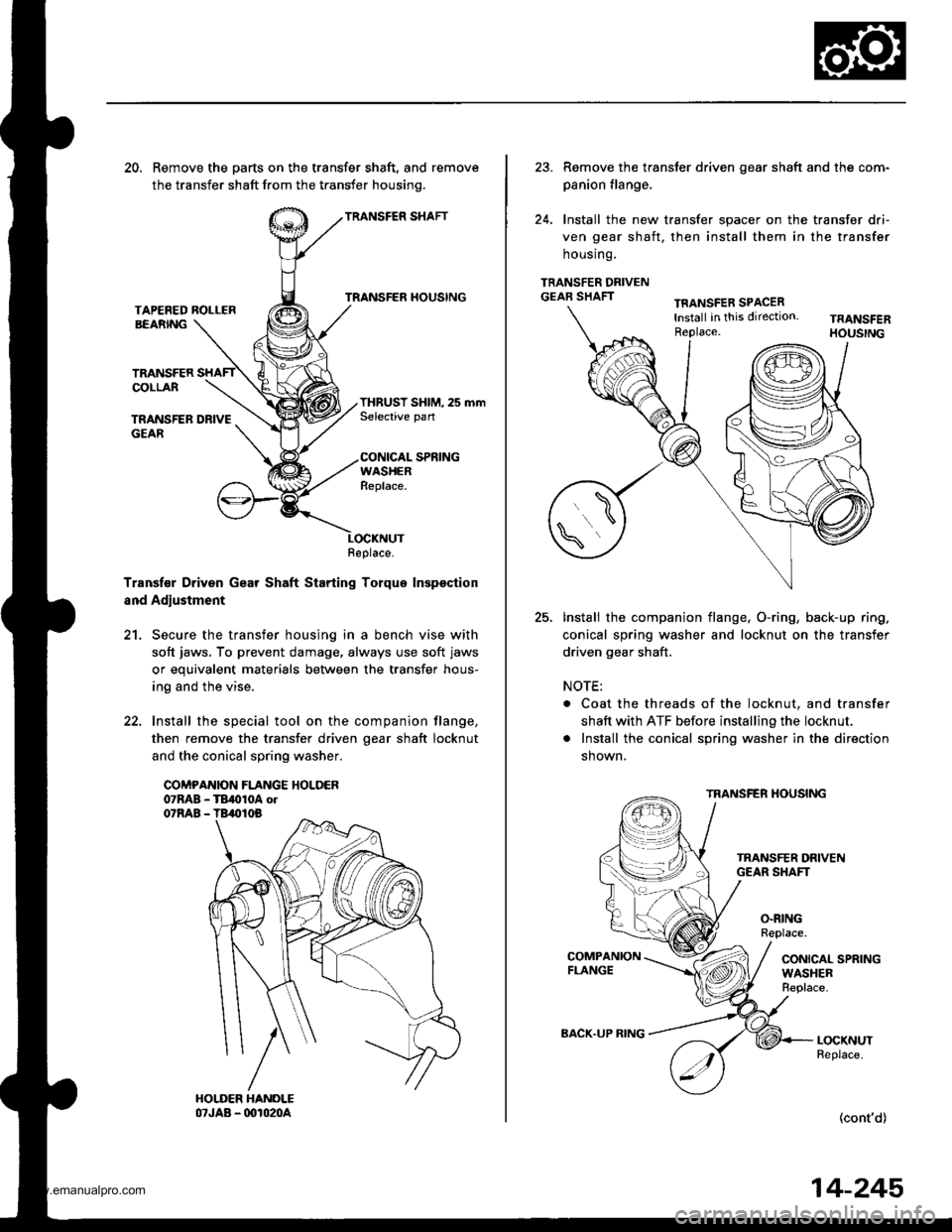
20. Remove the parts on the transfer shaft, and remove
the transfer shaft from the transfer housinq.
TRANSFER SHAFT
TRANSFER HOUSINGTAPEFED ROLLERBEARNG
TRANSFERCOLLAR
TRANSFER DRIVEGEAR
THRUST SHIM, 25 mmSelective pan
CONICAL SPRINGWASHERReplace.
Transf€r Driven Gear Shaft Starting Torque Inspsction
and Adjustment
21. Secure the transfer housing in a bench vise with
soft jaws, To prevent damage, always use soft jaws
or equivalent materials between the transfer hous-
ing and the vise.
22. Install the special tool on the companion flange,
then remove the transfer driven oear shaft locknut
and the conical spring washer.
COMPANION FLANGE HOLDER07RAB - TB,010A ol07RAB - TB,010B
Replace.
23. Remove the transter driven gear shaft and the com-
panion flange,
24. Install the new transfer spacer on the transfer dri-
ven gear shaft, then install them in the transfer
housrng.
TRANSFER DRIVENGEAR SHAFTTFANSFER SPACERlnstall in this direction.Replace.
25.Install the companion flange, O-ring, back-up ring.
conical spring washer and locknut on the transfer
driven gear shaft.
NOTE:
. Coat the threads of the locknut, and transfer
shaft with ATF before installing the locknut.
. Install the conical spring washer in the direction
shown,
TRANSFER HOUSING
O.RINGReplace.
CONICAL SPRINGWASHERReplace.
LOCKNUTReplace.
(cont'd)
BACK.UP RING
14-245
www.emanualpro.com
Page 762 of 1395
Transfer Assembly
Reassembly (cont'd)
Secure the transfer housing in a bench vise with
soft jaws. To prevent damage, always use soft jaws
or equivalent materials between the transfer hous-
ing and the vise.
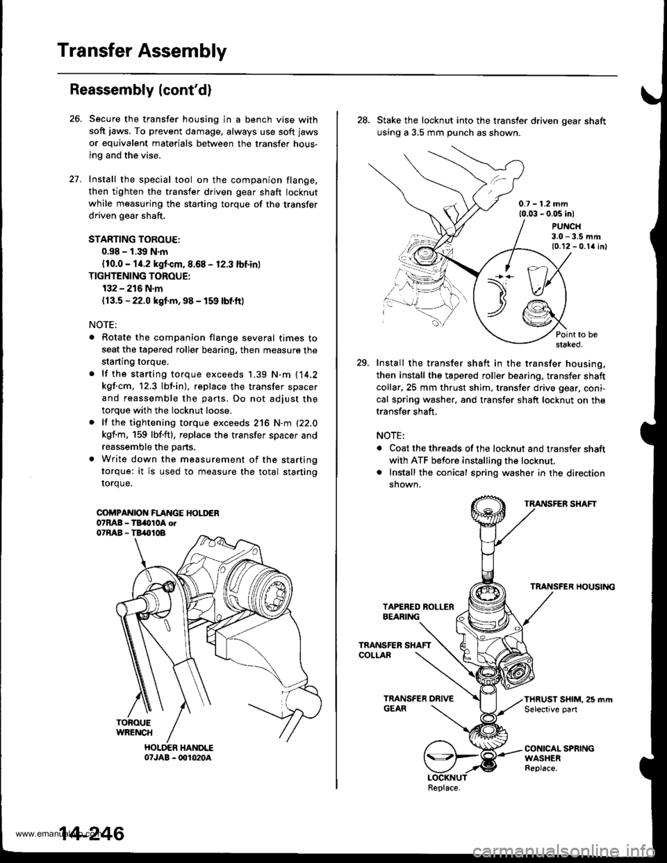
Install the special tool on the companion flange,
then tighten the transfer driven gear shaft locknut
while measuring the starting torque of the transfer
driven gear shaft.
STARTING TOROUE:
0.s8 - 1.39 N.m
{10.0 - 14.2 kgf.cm,8.68 - 12.3 lbf.in)
TIGHTENING TOROUE:
132 - 216 N.m
{13.5 - 22.0 kgf.m, 98 - 159 lbf.ft)
NOTE;
. Rotate the companion flange several times to
seat the tapered roller bearing, then measure the
starting torque,
. lf the starting torque exceeds 1.39 N.m (14,2
kgf.cm, 12.3 lbf.in), replace the transfer spacer
and reassemble the parts. Do not adjust the
torque with the locknut loose.
. lf the tightening torque exceeds 216 N.m (22.0
kgf.m, 159 lbf'ft), replace the transfer spacer and
reassemble the parts.
. Write down the measurement of the starting
torque: it is used to measure the total starting
rorque.
COi'PANIOI{ FLANGE HOLDER07MB - TBi(tloA otO'RAB - TB,.|}IOB
TOFOUEWRENCH
HOLDER HANDLE07JAB - 001020A
27.
14-246
28. Stake the locknut into the transfer driven gear shaft
using a 3,5 mm punch as shown.
0.7 - 1.2 mm{0.03 - 0.05 inl
PUNCH3.0 - 3.5 mm10.12 - 0.1{ inl
Point to bestaked.
29. Install the transfer shaft in the transfer housing,
then install the tapered roller bearing, transfer shaft
collar,25 mm thrust shim, transter drive gear, coni-
cal spring washer, and transfer shaft locknut on the
transfer shaft,
NOTE:
. Coat the threads of the locknut and transler shaft
with ATF before installing the locknut.. Install the conical spring washer in the direction
snown.
TRANSFER SHAFT
TRANSFER HOUSII{G
THRUST SHIM. 25 mrt|Selective part
CONICAL SPRINGWASHERReplace.
\t)t--/./
.,.-,.,\
Replace.
www.emanualpro.com
Page 763 of 1395
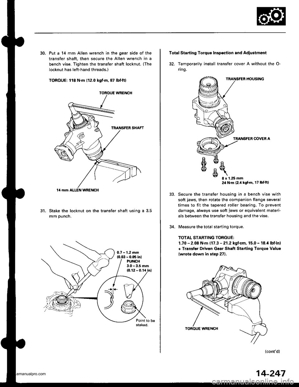
30. Put a 14 mm Allen wrench in the gear side of the
transfer shaft. then secure the Allen wrench in a
bench vise. Tighten the transfer shaft locknut. {The
locknut has left-hand threads,)
TOROUE: 118 N.m (12.0 kgf.m, 87 lbt.ft)
Stake the locknut on the transfer shaft using a 3.5
mm ounch.
al
14 mm ALI-EN WRENGH
0.7 - 1.2.nm{0.0:1- 0.C5 in}PU CH3.0 - 3.5 rnm
Total Starting Tolqu€ Insp€ction and Adiustment
32. TemDorarilv install transter cover A without the O-
flng.
HOUSING
TMNSFER COVER A
e
€
v
E- 8x1.25mm24 N'm {2.i1kgt'm, r? bt'ftl
Secure the transfer housing in a bench vise with
soft jaws, then rotate the companion flange several
times to fit the tapered roller bearing. To prevent
damage, always use soft jaws or equivalent materi-
als betlveen the transfer housing and the vise.
Measure the total starting torque.
TOTAL STARTING TOROUE:
1.70 - 2.08 N.m {17.3 - 21.2kgl.cm,15.0 - 18.i1 lbf.in}
+ Transler Driven Gear Sh8ft Starting Torque Value
lwroto down in step 27).
(cont'd)
5J.
34.
14-247
www.emanualpro.com
Page 765 of 1395
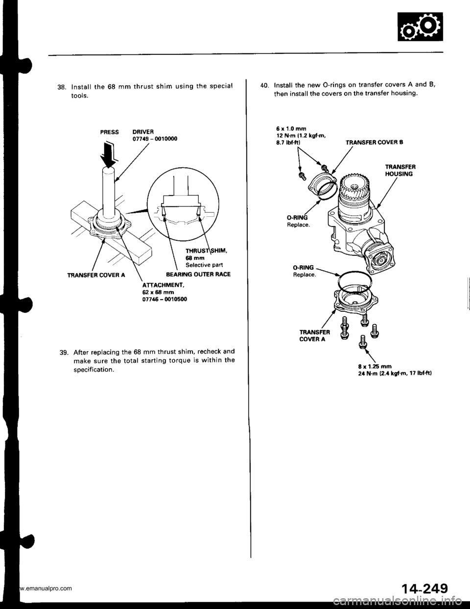
38. Install the 68 mm thrust shim using the special
tools.
PRESSDRIVER07743 - 001 0000
ATTACHMENT,62x68mrr|077a6 - (x)10500
39.After replacing the 68 mm thrust shim. recheck and
make sure the total starting torque is within the
specification.
AEARING OUTER RACE
40. Install the new O-rings on transfer covers A and B,
then installthe covers on the transfer housing
6x1.0mm12 N.m 11.2 kgt.D,8.7 rbf.ftlTRANSFEN COVER B
O.RINGReplace.
8 r 1.25 rnm24 N.m 12.4 kgl.m, 17 lbf'ftl
Replace.
www.emanualpro.com
Page 766 of 1395
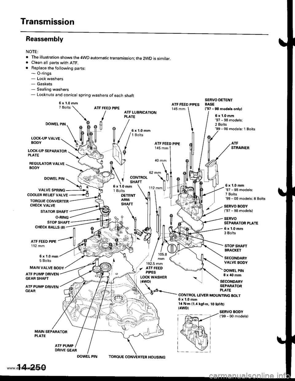
Transmission
Reassembly
NOTE:
. The illustration shows the 4WD automatic transmission; the 2WD is similar.. Clean all parts with ATF.. Replace the following parts:- O-rings- Lock washers- Gaskets- Sealing washers- Locknuts and conical spring washers of each shaft
ATF FEED PIPE
/
ATF FEED PIPES145 mm
SERVO DETENTBASE(37 -98 modeb onlylATF LUBRICATIONPLATE6x1.0mm
2 Bolts'99 - 00 models: 1 Bolts
LOCK.UP VALVEBODY
LOCK.UP SEPARATORPLATE
REGULATOR VALVEBODY
DOWEL PIN
DOWEL PIN
VALVE SPRING
STATOR SHAFT
'-
'112mmll,
rlT
ATFSTRAINER
40 mm
j coNrRoLI SHAFT
COOLER BELIEF VALVE
TOROUE CONVERTERCHECK VALVE
6x1.0mm18olts
DETENTARMSHAFT
6x1,0mm'97 - 98 models:7 Bolts'99 - 00 models:8 Bolts
SERVO BODY('97 - 98 models)
SERVOSEPARATOR PLATE
6x1.0mm3 Bolts
STOP SHAFTBRACKET
SECONDARYVALVE BODY
OOWEL PIN8x40mm
O.RING
STOP SHAFTCHECK BALLS 18'
ATF FEED PIPE112 mm
6x1.0mm5 Eolts
ATF PUMP DRIVENGEAR SHAFT
ATF PUMP DRIVEN
MAIN SEPARATORPLATE
MAIN VALVE EOOY
SECONDARYSEPARATOR
d---.- PLATE--.- CONTROL I.EVER MOUNTING BOLT6x1.0ftm14 N.m (1.4 kgt.m, 10 tbf.ft)(4WD)SERVO BODY('99 - 00 models)
ATF PUMP
6x1.0mm
ATF FEEO PIPE
) / 105.8
/,,!.,::(./ afF FEEO,/ ptpEs
EP,---!ir{+*a r
fpffi4 i
x*hi
_ \zl
14-250
DRIVE GEAR
DOWEL PINTOBOUEHOUSING
www.emanualpro.com
Page 767 of 1395

1.Install the suction pipe collar and the ATF magnet
{2WD) in the torque converter housing, if necessary.
lnstall the main seDarator Dlate and the two dowel
pins on the torque converter housing,
Install the ATF pump drive gear. ATF pump driven
gear, and ATF pump driven gear shaft on the torque
converter housing. Installthe ATF pump driven gear
with its grooved and chamfered side facing down.
ATF PUMPGEAR
ATF PUMP D{IVEf{GEAR SHAFT
ATF PUi'PORIVEN GEAR
Grooved and chamteredside faces separatorplate.
MAIN S€PAR/ATORPLATE
5.
o.
Loosely install the main valve body with five bolts.
Make sure the ATF pump drive gear rotates smoothly
in the normal operating direction, and the ATF pump
driven gear shaft moves smoothly in the axial and
normal operating directions.
Install the secondary valve body, separator plate,
and two dowel pins on the main valve body. Do not
installthe bolts.
Install the control shaft in the housing along with
the manual valve.
lnstall the detent arm and arm shaft in the main
valve body, then hook the detent arm spring to the
detent arm.
SEBVO SEPARATOR PLATE
7.
DETENT ARMSHAFT
OETENT ARM
CONTROLSHAFT
MANUAL VAIVE
OETENT ARM SPRING
onlv on the '98 - 00 models,
14-251
1l.
9.
8.
10.
Install the servo body and separator plate on the
secondary valve body ('97 - 98 models: seven bolts,'99 - 00 models: eight bolts).
lnstall the servo detent base ('97 - 98 models only)
and the ATF strainer ('97 - 98 models: two bolts,'99 -
00 models: one boltl.
Tighten the five bolts on the main valve body to 12
N'm (1.2 kgf.m, 8.7 lbf.ft).
Make sure the ATF pump drive gear and ATF pump
driven gear shaft move smoothly. lf they don't,
loosen the bolts on the main valve body, and disas-
semble the valve bodies. Realign the ATF pump driv-
en gear shaft and reassemble the valve bodies, then
retighten the bolts to 12 N.m (1.2 kgim, 8.7 lbf.ft).
CAUTION: Failure to align the ATF pump driven
gear shaft corroctly will rosult in a seizsd ATF pump
drive gear or ATF pump drivon gear shaft.
ATF PUMP ATFGEARDRIVE GEAR DBIVEN GEARSHAFT
Install the stator shaft and stop shaft
Install the bolts and the stop shaft bracket on the
secondary valve body, then tighten the bolts (three
bolts).
Install the torque converter check valve, cooler relief
valve, and valve springs in the regulator valve body,
then install the regulator valve body on the main
valve body {one boltl.
Install the lock-up valve body, separator plate, two
dowel pins and lubrication plate (eight bolts).
Installthe one ATF feed pipe in the main valve body,
the three ATF feed pipes in the secondary valve, the
three ATF feed pipes in the servo body and the one
ATF feed pipe in the lock-up valve body.
NOTE: lnstall the 105.8 mm ATF feed pipe with its
filter side away from the secondary valve body; the
filter is on the 105.8 mm ATF feed pipe, which is(cont'd)
13.
14.
15.
16.
www.emanualpro.com