Page 444 of 1395
Removal
!@@ Make sure the lifts, i8cks. and safety stands
are placed properly {see section 1}.
1. Raise the front of the vehicle, and support it with
safety stands (see section 1).
2. Set the parking brake, and block both rear wheels
securely.
3. Drain the manual transmission fluid Reinstall the
drain plug with a new sealing washer.
4. Disconnect the heated oxygen sensor (HO2S) con-
nector.
SELF.L(rcKNGNUTReplace.
SELF-LOCKI'{GNUTReplac€.
5. Remove exhaust oipe A.
6. Make reference marks across the propeller shaft
and the transfer assembly flanges'
Separate the propeller shaft from the transfer
assembly flanges,
Remove the rear stiffener, then remove the transfer
assembly.
NOTE: While servicing the transfer assembly, do
not allow dust or other foreign particles to enter the
transmission.
7.
REFEREI{CE i'ARKS
Replace.
Replace.
13-5
www.emanualpro.com
Page 445 of 1395

Transfer Assembly
lnstallation
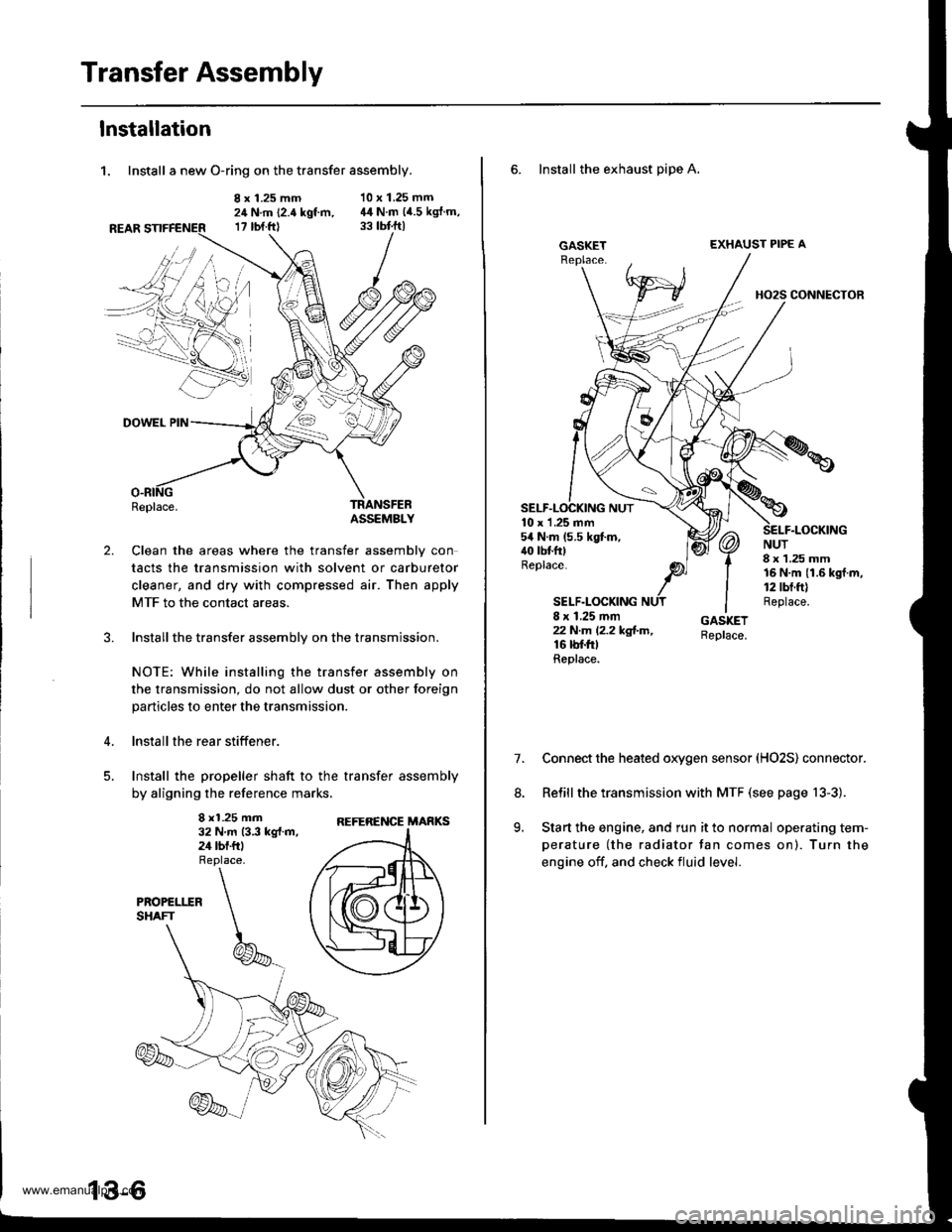
1. Install a new O-ring on the transfer assembly.
8 x 1.25 mm24 N.m (2.4 kgt m,17 rbt.ftl
10 x 1.25 mm44 N.m (4.5 kgJ.m,
2.
DOWEL PIN
Replace.TRANSFEBASSEMBLY
Clean the areas where the transfer assembly con
tacts the transmission with solvent or carburetor
cleaner, and dry with compressed air. Then apply
MTF to the contact areas.
Installthe transfer assembly on the transmission.
NOTE: While installing the transfer assembly on
the transmission, do not allow dust or other foreign
particles to enter the transmission.
lnstall the rear stiffener.
Install the propeller shaft to the transfer assembly
by aligning the reference marks,
8 x1.25 mm32 N.m 13.3 kg{.m,24 tbf.ftl
REFERENCE MARKS
6. Install the exhaust pipe A,
GASKETEXHAUST PIPE A
HO2S CONNECTOR
10 x 1 .25 mm54 N.m (5.5 kgt m,40 tbtfttReplace.
SELF.LOCKING
NUT8 x 1.25 mm16 N.m {1.6 kgf.m,12 tbt.ft)Replace.8 x 1.25 mmzzN.m l2.2kg!-m,16 rbf.trtReplace.
7.Connect the heated oxygen sensor (HO2S) connector.
Relill the transmission with MTF (see page 13-3).
Start the engine, and run it to normal operating tem-
perature (the radiator tan comes on). Turn the
engine off. and check fluid level.
8.
9.
www.emanualpro.com
Page 512 of 1395
8. Installthe right front mounvbracket.
12 x 1 .25 mm64 N.m (6.5 kgf'm,47 tbf.ftlReplace.
RIGHT FRONTMOUNT/BBACKET
10 x 1.25 mm4,a N.m (4.5 kgf m,
33 tbf ftl
Install the clutch housing cover and rear engine
stiffener.
6xl0mm12 N.m 11.2 kgt.m.8.7 tbf.ft)
HOUSING
'12 x 1.25 mm29 N.m 13.0 kgf.m. 22 lbf'ft)
8 x 1.25 mm24 N.m {2.5 kgf'm'
18 tbl.ft)
10 x 'l .25 mm44 N.m {4.5 kgf m,33 lbf ftl
10. Pour transmission fluid of 1 liter from the driveshaft
inserted hole.
1 1. lnstall the intermediate shaft {see section 18). While
installing the intermediate shaft in the differential.
be sure not to allow dust and other foreign particles
to enter the transmission.
10 r 1.25 mm39 ttm 14.0 kgf.m,29 tbt ftlSET RINGReplace.
12. lnstall the driveshafts (see section 18). While
installing the driveshaft(s) in the differential, be sure
not to allow dust and other foreign panicles to enter
the transmission.
SET RINGReplace.
(cont'd)
13-73
INTERMEOIATE SHAFT
DRIVESHAFT
www.emanualpro.com
Page 682 of 1395
Transfer Assembly
Removal (cont'dl
9, Make reference marks across the prooeller shaftand the transfer assembly flanges.
10. Separate the propeller shaft from the transferassembly flanges.
PROPELLERSHAFT
Remove the rear stiffener. then remove the transferassembly.
NOTE: While servicing the transfer assembly, donot allow dust or other foreign particles to enter thetransmission.
'l l.
REFERENCE MANKS
REAR STIFFENER
14-166
www.emanualpro.com
Page 683 of 1395
lnstallation
Install a new O-ring on ths transfer assembly.
Clsan the areas where the transfer assembly con-
tacts the transmission with solvent or carburetor
cleaner, and dry with compressed air. Then apply
ATF to the contact areas.
Install the transter assembly on the transmission.
NOTE: while installing the transfer assembly, do
not allow dust or other foreign particles to enter the
transmission.
lnstall the rear stiffener.
1.
8 r 1.25 mm24 N.m {2.4 kgf m,
r7 bl.ftl
TNANSFERASSEMALY
10 x'l.25 mmara N.m 14.5 kgtm,33 tbf trl
O.RING
5. Install the propeller shaft to the transfer assembly
by aligning the reference marks
PROPELLERSHAFT
8 xl,25 ]nm32 N.m (3.3 kgl.m,2a tbf.ftlReplace.
Install the shift cable with the control pin, then
secure it with the snap pin. Do not bend the shift
cable excessively.
lnstallthe shift cable cover.
SHIFT CABLE
7.
8 xl.25 mm22 N.m 12.2 kd-m,16 tbt.ftl
(cont'd)
REFERENCE MARKS
14-167
www.emanualpro.com
Page 688 of 1395
Transmission
21.
Removal (cont'dl
Make reference marks across the transfer assemblv
and propeller shaft flanges. (4WD)
Separate the propeller shaft from the transfer
assembly. (4WD)
I x 1.25 mmReplace.
Remove the intermediate shaft,
Tie plastic bags over the both ends of the intermedi-
ate shaft. Coat all precision finished surfaces with
clean engine oil.
22.
REFERENCE MARKS
14-172
24.Remove the right front mounvbracket.
Remove the ATF cooler hoses at the ATF cooler
lines. Turn the ends of the cooler hoses uo to ore-
vent ATF from flowing out, then plug the lines and
hoses. Check for any sign of leakage at the hose
ioints.
RIGHT FRONTMOUNT/BRACKET
Remove the rear stiffener and torque converter
cover.
Remove the eight drive plate bolts, one at a time.
while rotating the crankshaft pulley.
27.
COVER
DRIVE PLATE
www.emanualpro.com
Page 776 of 1395

Transmission
Installation (cont'dl
8. Install the transmission housing mounting bolts.
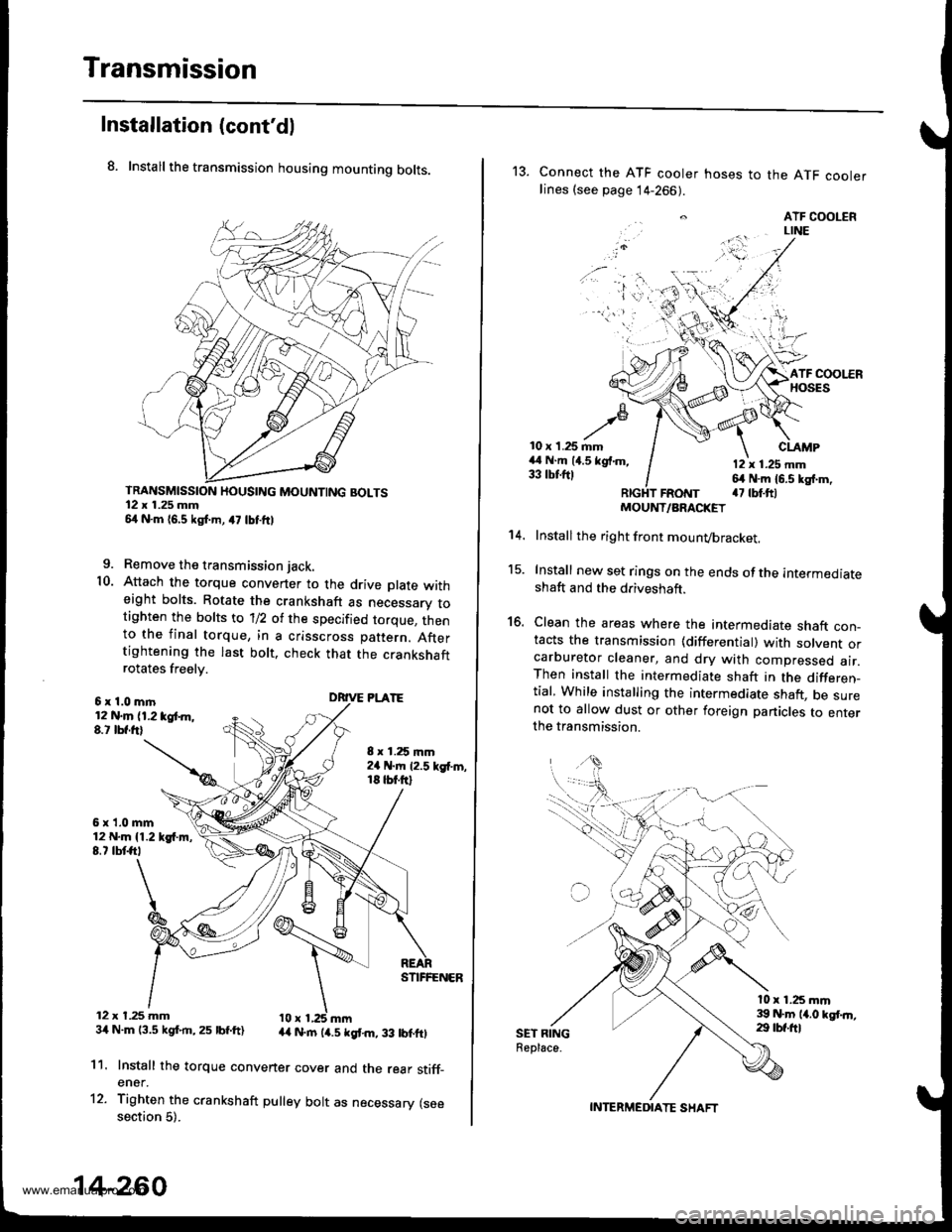
TRANSMISSION HOUSING MOUNTING BOLTS12 x 1.25 mm54 N.m 16,5 kgf.m, a7 lbtftl
9. Remove the transmission jack.
10. Attach the torque convener to the drive plate witheight bolts. Rotate the crankshaft as necessarv totighten the bolts to 'll2 of the specified torque, thento the final torque, in a crisscross pattern. Aftertightening the last bolt. check that the crankshaftrotates freelv.
6x1.0mln12 N.m (1.2 tgt m,8.t lbf.frl
6x1.0mm12 N.m {1.219{.m,8.7 tbtft,
12 x t.25 mm34 N.m 13.5 kgf.rn,25 lbf.ft)
8 x 1.25 mm2a N.m 12.5 kgf'm,18 tbt.ftl
DRIVE PLATE
STIFFENER
44 N.rn (4.5 kgt m, 33 lbtftl
11.
12.
Install the torque convener cover and the rear stiff_ener.
Tighten the crankshaft pulley bolt as necessary (seesection 5).
14-260
13. Connect the ATF cooler hoses to the ATF coolerlines (see page 14-266).
. ATF COOLERLINE
'i 'l'r',:,.) -
10 x 1.25 mm44 N.m (4.5 kgf.m,33 tbtftl
CLAMP
12 x 1.25 mm64 N.m 16.5 kg{.m,a7 tbt.ftlFRotrtT
15.
16.
't 4.
SET RINGReplace.
MOUNT/ARACKET
Install the right front mounvbracket.
Install new set rings on the ends of the intermediateshaft and the driveshaft.
Clean the areas where the intermediate shaft con_tacts the transmission {differential) with solvent orcarburetor cleaner, and dry with compressed air.Then install the intermediate shaft in the differen_tial, While installing the intermediate shaft, be surenot to allow dust or other foreign panicles to enterthe transmission.
l0 x 1.25 mm39 N.m 14.0 kgt.n,29 tbf.ftl
INTERMEDIATE SHAFT
www.emanualpro.com
Page 878 of 1395
REAR MOUNT
20. Remove the rear mount bracket and rear mount.
12 x 1.25 mmReplace.
REAR MOUNT BRACKET12 x 1.25 mmReplace.
21.
14 x 1.5 mmReplaco.
Place a jack under the engine block in the area
shown,
?*
JACK.UP POINT
17-33
22. Jack up the engine and tilt the engine back until the
transfer assembly is lowered approximately 40 mm
(1.57 in).
Note these items when tilting the engine:
. Check that the wire harnesses, hoses and pipes
are not caught by any surrounding parts.
. Do not tilt the engine more than necessary.
ASSEMBLY
Remove the stiffener olate.
NOTE: Some stiffener plate mounting bolts a.e also
used as gearbox mounting bolts. The gearbox will
tilt to the side when these bolts are removed.
(cont'd)
.Lower approximately'40 mm (1.57 in)
STIFFENER PLATE
www.emanualpro.com