Page 1190 of 1395

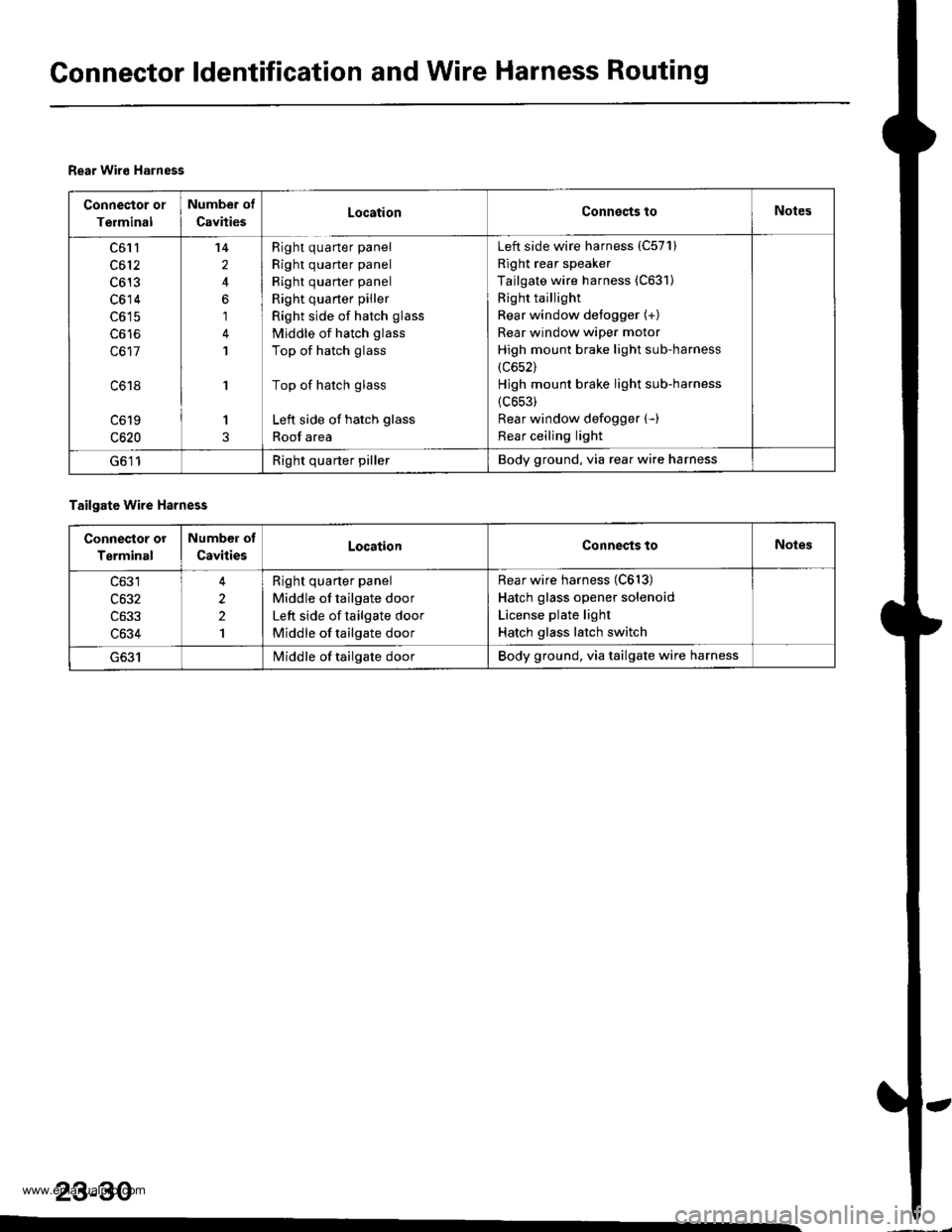
Gonnector ldentification and Wire Harness Routing
Rear Wiro Harness
Connector or
Terminal
Number of
CavitiesLocationConnects toNotes
c61l
c612
c613
c614
c617
c618
c619
c620
14
2
6
1
1
'I
1
Right quarter panel
Right quarter panel
Right quarter panel
Right quaner piller
Right side of hatch glass
Middle of hatch glass
Top of hatch glass
Top of hatch glass
Left side of hatch glass
Roof area
Left side wire harness (C57'l)
Right rear speaker
Tailgate wire harness (C631)
Right taillight
Rear window defogger (+)
Rear window wiper motor
High mount brake light sub-harness
(c652)
Hjgh mount brake light sub-harness
{c653)
Rear window defogger (-)
Rear ceiling light
G611Right quarter pillerBody ground, via rear wire harness
Tailgate wire Harness
Connestor or
Terminal
Number of
CavitiesLocationConnects toNoles
c633
c634
2
2
1
Right quarter panel
Middle of tailgate door
Left side of tailgate door
Middle of tailgate door
Rear wire harness (C613)
Hatch glass opener solenoid
License plate light
Hatch glass latch switch
I/iddle of tailgate doorBody ground, via tailgate wire harness
23-30
www.emanualpro.com
Page 1203 of 1395

Power Distribution
Fuse-to-Gomponent(sl Index (numerical sequence)
Under-hood Fuse/Rolay Box:
41
43
44
46
47
48
49
50
52
Capacity
'100 A
40A
7.5 A
15 A
40A
7.5 A
30A
204
204
15 A
10A
40A
40A
204
20A
Capacity
40A
204
7.5 A
wiro ColorFuseCircuit(s) Prot€cted
A
lgnition switch (BAT)
lntegrated control unit
Ceiling lights
Spotlights
PGM-Fl main relay
Not used
No. 7, 8, 10, 11 fuse in the under-dash fuse/relay box
Audio unit
Clock {'98 - 00 models)
Data link connector ('98 - 00 models)
ECM (VBU) {'98 - 00 models: M/T)
Heater control panel
PCM (VBU) (A./T)
Combination light switch (via under-dash fuse/relay box)
No. 20, 33 fuse in the under-dash fuss/relay box
Not used
Rear window defogger (via relay)
Door lock control unit
Hatch glass opener solenoid
Keyless door lock control unit ('98 - 00 models)
Horn relay
Horns (via relay)
via brake switch:
ABS control unit
Brake lights
Cruise control unit
ECM ('98 - 00 models: M/T)
High mount brake iight
PCM (4./T)
Trailer lighting connector
Turn signal/hazard relay (via switch)
Option connector (+B)
No. 6 fuse in the under-dash fuse/relay box
Blower motor (via relay)
Condenser fan motor (via relay)
Ay'C compressor clutch (via relay)
Radiator fan motor (via relay)
Wire Color Circuitls) Protoct
53
54
50
WHT/BLK
WHT/RED
WHT/BLK
WHT/BLU
WHT/BLU
WHT
WHT/GRN
WHT/GRN
WHT/GRN
WHT/BLK
WHT/RED
BLU/WHT
WHT
RED
BLK/RED
Under-hood ABS Fuss/nehy Box:
Fusg
61WHT
WHT/GRN
BRN/YEL
ABS pump motor {via relay}
ABS control unit
ABS control unit
{cont'd)
23-43
www.emanualpro.com
Page 1208 of 1395
Ground Distribution
Ground-to-Component(sl Index (cont'dl
Wire ColorGround
G552
G501
G801
BLK
BLK
BLK
BLK
Component or Circuits Grounded
Audio unit
Driver's door lock actuator (door lock knob switch)
Driver's door lock switch
Driver's power window motor
Keyless door lock control unit ('98 - 00 models)
Power door lock control unit
Power mirror switch
Power window master switch
Driver's seat belt switch
Fuel gauge sending unit
Fuel pump (FP)
Left rear side marker light
Left taillight
Rear accessary socket
Right rear side marker light
Trailer lighting connector
High mount brake light
Rear window defogger
Rear window wiper motor
Rjght taillight- plus eveMhing grounded through G631
Hatch glass opener solenoid
License plate light- plus eveMhing grounded through G6l1
SRS unit
BLK
BLK
BLK
23-48�
www.emanualpro.com
Page 1209 of 1395

Under-dash Fuse/Relay Box
I
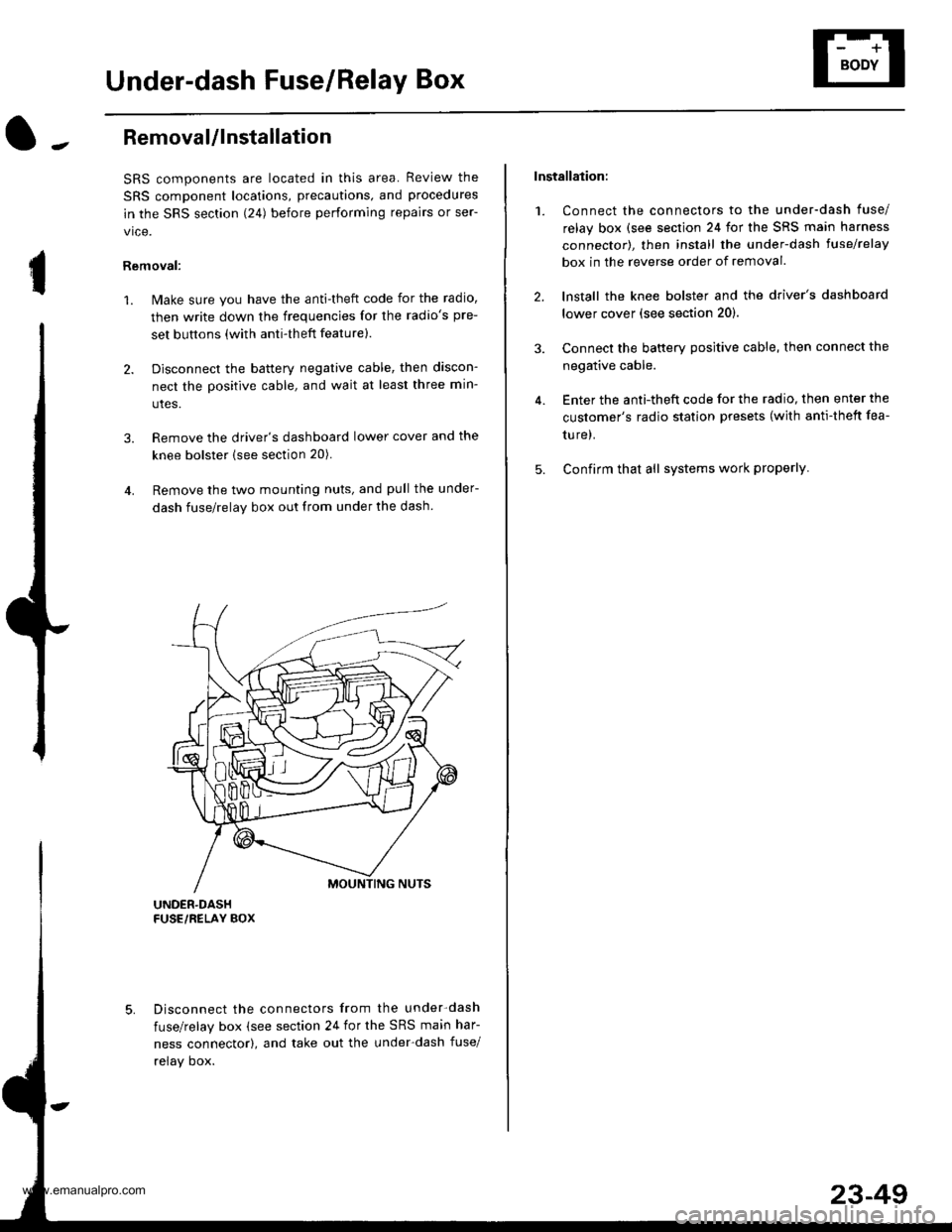
Removal/lnstallation
SRS components are located in this area. Review the
SRS component locations, precautions, and procedures
in the SRS section (241 before performing repairs or ser-
vice.
Removal:
1. Make sure you have the anti-theft code for the radio,
then write down the frequencies for the radio's pre-
set buttons (with anti-theft feature).
2. Disconnect the battery negative cable, then discon-
nect the positive cable, and wait at least three min-
utes.
3. Remove the driver's dashboard lower cover and the
knee bolster (see section 20).
4. Remove the two mounting nuts, and pull the under-
dash fuse/relay box out from under the dash
Disconnect the connectors from the under-dash
fuse/relay box (see section 24 for the SRS main har-
ness connector), and take out the under-dash fuse/
relay oox.
Installation:
1. Connect the connectors to the under-dash fuse/
relay box (see section 24 for the SRS main harness
connector), then install the under-dash lusehelay
box in the reverse order of removal.
2. lnstall the knee bolster and the driver's dashboard
lower cover (see section 20).
3. Connect the battery positive cable, then connect the
negative cable.
4. Enter the anti-theft code for the radio, then enter the
customer's radio station presets (with anti-thett fea-
ture).
5. Confirm that all systems work properly
23-49
www.emanualpro.com
Page 1221 of 1395
Removal
'1. Remove the two screws from the instrument panel.
2. Remove the instrument panel carefully to avoid damaging the clips.
3. Tilt the steering wheel down with the tilt adjustment lever.
4, Spread a protective cloth over the steering column.
5. Remove the four mounting screws from the gauge assembly.
6. Pullthe gauge assembly out, and disconnect all connectors from it.
7, Remove the gauge assembly.
GAUGE ASSEMELY
INSTRUMENT PANEL
23-61
www.emanualpro.com
Page 1235 of 1395
Lighting System
l-.Component Location Index
DAYNME RUNNING LIGHTSREslsToi lCan!drlTest, page 23-80
I{IGH BEAM INOICATOR I-IGHT
COMBINATION LIGHT SWTCHTest, page 23-78
DAYTIME RUNNING LIGHTSCONTROL UNIT lCanadalInput Test, page 23-79
Replac€ment, Page 23-80
Adjustment, Page 23-81
HIGH MOUNT BRAKE LIGHTReplacement, page 23-84
FRONT TURN SIGNAL LIGHT/FRONT SIDE MARKER LIGHTReplacemont, page 23-80
BRAKE/PARKING LIGHT
Replacement, page 23-82
BACK.UP LIGHTReplacement, page 23-82
23-75
www.emanualpro.com
Page 1240 of 1395

Lighting SystemHeadlights
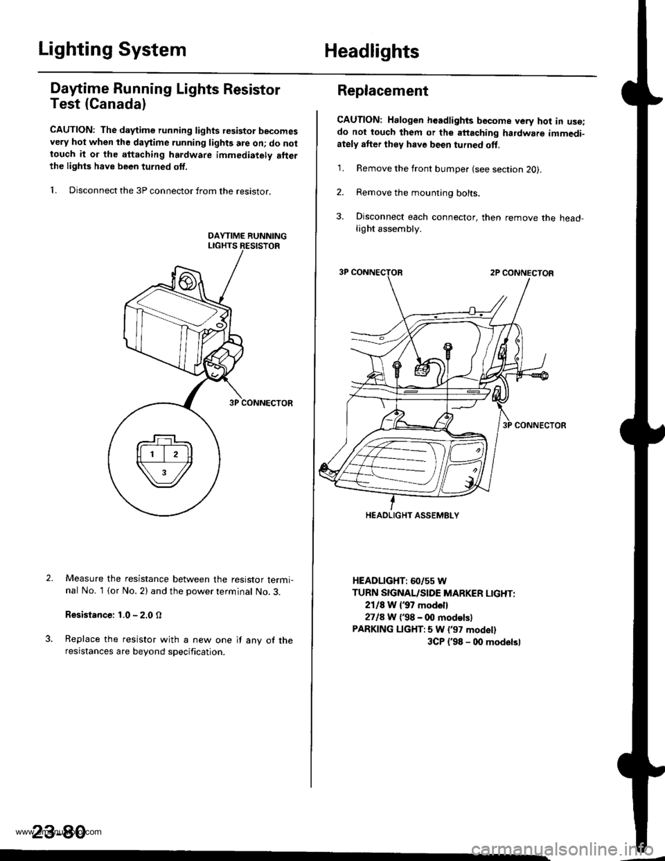
Dafime Running Lights Resistor
Test (Canada)
CAUTION: The d.ytime running lights resistor becomesvery hot when the daytime running lights are on; do nottouch it or the attaching hardware immediately allerthe lighls have been turned off.
1. Disconnect the 3P connector from the resistor.
Measure the resistance between the resistor termi-nal No. 1 (or No. 2) and the power terminal No. 3.
Resistance: 1.0 - 2.0 O
Replace the resistor with a new one if any of theresistances are beyond specification.
23-80
Replacement
CAUTION: Halogen headlights bGcome very hot in use;do not touch them or the attaching hardware immedi-ately after they have been turned oft.
1. Remove the front bumper (see section 2O).
2. Remove the mounting bolts.
3. Disconnect each connector, then remove the head-light assembly.
HEADLIGHT: 60/55 W
TURN SIGNAL/SIDE MARKER LIGHT:
2118 W {37 model}
2718 W ('98 - 00 modelsl
PARKING LIGHT:5 W l'97 modell
3CP {'98 - 00 modelsl
HEADLIGHT ASSEMELY
www.emanualpro.com
Page 1244 of 1395
Brake Lights
High Mount Brake Light
Replacement
1. Push the clips, and remove the cover from thehousing.
Disconnect the connectors.
Remove the two nuts and the housing.
2.
HOUSING
Gircuit Diagram
UNDER.HOODFUSE/RELAY BOXBATTENY
/,i | No.s2 {15A) |
\Y*-I=f*-'o*T*'no"l
IV
T:,^-,
HORNSYSTEM
I
i.t53l| *",*"",
GRNA,VHT
GBNMHT -.1
I
I
. ABS CONTFOLUNIT' ECM/PCM. CRUISE CONTROLUNIT
GRNAVHT GRNWH
ll
tl
A[$^Jlr A
Yi,?'il Y
tlBLK BLK
llrl
IBLK
I
I
d
oi,,
RIGHTEFAKELIGHT(21w)
LEFIBFAKELIGHT(2rw)
BLK
G553
23-84
www.emanualpro.com