Page 1254 of 1395
Interior Lights
Ceiling Laght Test
Front and rgar:
1. Turn the light switch OFF.
2. Pry off the lens.
3. Remove the two mounting nuts and the housing.
4. Disconnect the 3P connector from the housing.
Check for continuity between the terminals in each
switch position according to the table.
t€rmtnar
Position \
1or1'�2'3'�3
OFFo-Pd'l-o
MIDDLEo-/=\-o
ONo-/a\-o\:/
23-94
1 1' 3' 2'
Spotlight Test
1. Turn the spotlight switch OFF.
2. Pry off the lens.
3. Remove the two screws and the housing.
4. Disconnect the 3P connector from the housing.
Check for continuitv between the terminals in each
switch position according to the table,
Terminal
t"",rr" \12ol2'�3
R
ONo-/-\--o\:./
OFFo@o
L
ONo-/a--o\:./
OFFo-(9--o
aULB(5Wx2l
www.emanualpro.com
Page 1262 of 1395

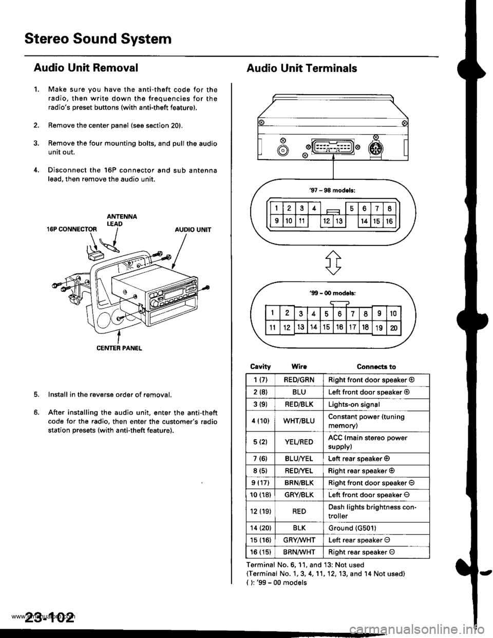
Stereo Sound System
Audio Unit Removal
Make sure you have the anti-theft code for the
radio, then write down the frequencies for the
radio's preset buttons (with anti-theft feature).
Remove the center panel (see section 201,
Remove the four mounting bolts, and pull the audio
unit out.
Disconnect the 'l6P connector and sub antenna
lead, then remove the audio unit.
Install in the reverse order of removal.
After installing the audio unit, enter the anti-theft
code for the radio. then enter the customer's radio
station presets (with anti-theft feature).
1.
AUDIO UNIT
CENTEB PANEL
23-102
Audio Unit Terminals
CavrtyWireConnoct3 to
Terminal No.6, 11, and 13: Not used(Terminal No. 1,3, 4,'11,12, 13, and '14 Not us6d)
{ ): '99 - 00 models
1{7)RED/GRNRight front door speaker @
2 {8}BLULeft front door speaker @
3 {9)RED/BLKLights-on signal
4 (10)WHT/BLUConstant power (tuning
memory)
5 (2)YEUREDACC (main sterso power
supplyl
7 (6)BLU/YELLeft rear soeaker @
8 (s)RE D/VELRight rear speaker @
9 (17)BRN/BLKRiqht f.ont door speaker O
10 (18)GRY/BLKLeft front door soeaker O
12 (19)REDDash lights brightness con-
troller
14 (20)BLKGround (G501)
15 (16)GRYMHTLeft rear speaker O
16 (15)BRN^ll/HTRight resr speaker O
www.emanualpro.com
Page 1263 of 1395
Speaker Replacement
1. Remove the speaker cover.
2. Remove the three screws from the speaker.
3. Disconnect the 2P connector, and remove the door
speaker.
Front speaker:
2P CONNECTOR
Rear speaker:
/a--=-
ll-
FRONT SPEAKER
SPEAKERCOVER
4-
23-103
Mast Antenna Replacement
NOTE: To remove the antenna lead, it is necessary to
remove the dashboard (see section 20).
1. Disconnect the antenna lead from the audio unit.
2. Remove the two mounting screws, then remove the
mast antenna.
MOUNTING SCREWS
www.emanualpro.com
Page 1269 of 1395
J-
Switch Test
1. Remove the switch as described in Function Test
{see page 23-108).
2. Check Jor continuity between the terminals in each
switch position according to the table.
POWER MIRRORswtTcH
Teminal
t*t* \
2345b8I
L
UPoooo
DOWNoooo
LEFTo.ooo
RIGHToooo
R
UPoooo
DOWNoooo
oooo
RIGHToooo
23-109
Actuator Test
1. Prv out the mirror mount cover (see section 20).
2. Disconnect the 8P connector from the power mirror.
Check actuator operation by connecting power and
ground according to the table.
MIRROR MOUtrlTCOVER
Terminal
;;,i". -\18
TILT UP@
TILT DOWN@
SWING LEFTo@
SWING RIGHT@o
www.emanualpro.com
Page 1282 of 1395
Hatch Glass Opener
Solenoid Test
1. Open the tailgate and remove the tailgate trim (see
section 20).
2. Disconnect the 2P connector from the solenoid.
Terminalsade ofmale termtnals
Connect power to the No. 1 terminal and ground to
the No.2 terminals momentarilv. The solenoid
should ooerate.
SOLENOID
23-122
't.
2.
4.
Solenoid Replacement
Remove the tailgate trim (see section 20).
Disconnect the 2P connector.
Remove the rod from the key cylinder.
Remove the three mounting bolts, then remove the
solenoid.
Install the replacement solenoid in the reverse oader
of removal.
www.emanualpro.com
Page 1289 of 1395
Passenger's Door Lock Actuator Test
Remove the passenger's door panel (see section 20).
Disconnect the 2P connector from the actuator.
NOTE: The left rear door lock actuator is shown;
the front passenger's and right rear door lock actua-
tors are similar.
Terminal side ofmale terminals
Check actuator operation by connecting power and
ground according to the table. To prevent damage
to the actuator, apply battery voltage only momen-
raflry.
Terminal
;;il;--r
,l
LOCK@
UNLOCK@
1.
2P CONNECTOR
4. lf the actuator does not work properly, replace it.
23-129
L
Driver's Door Lock Switch Test
Remove the inner handle {see section 20).
Disconnect the 3P connector. then remove the two
mounting screws and driver's door lock switch.
Check for continuitv between the terminals in each
switch position according to the table.
lermlnal
Position \
123
LOCKo---o
OFF
UNLOCKo--_o
www.emanualpro.com
Page 1297 of 1395

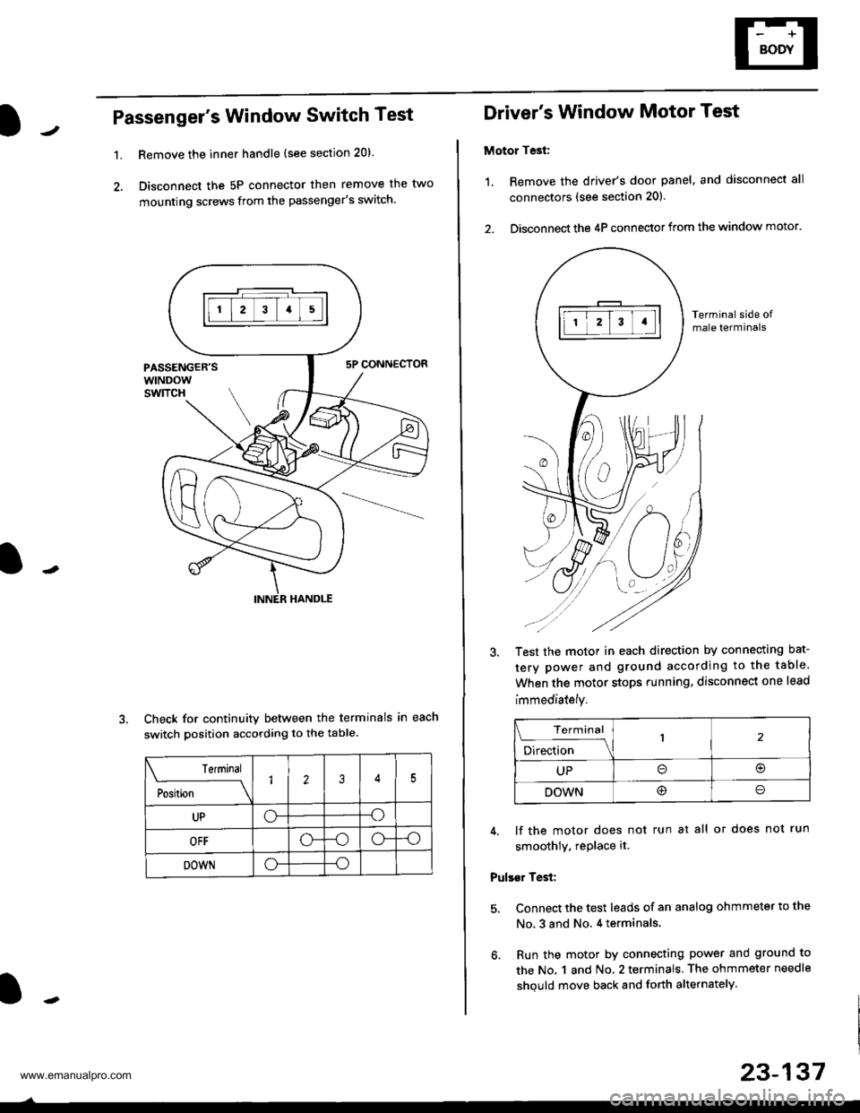
Passenger's Window Switch Test
1.Remove the inner handle (see section 20).
Disconnect the 5P connector then remove the two
mounting screws from the passenger's switch.
Check for continuity between the terminals in each
switch position according to the table
Terminal
;"rL-
__\1235
UPo--o
OFF-oo--o
DOWNo--o
Driver's Window Motor Test
Motor Test:
1. Remove the driver's door panel, and disconnect all
connectors (see section 201.
2. Disconnect the 4P connector from the window motor.
Terminal side ofmale terminals
Test the motor in each direction by connecting bat-
tery power and ground according to the table.
When the motor stops running. disconnect one lead
immediately.
Terminal
;;b"
-\
UPo(!r
DOWN@o
4. lf the motor does not run at all or does not run
smoothly. rePlace it.
Pulser Test:
5. Connect the test leads of an analog ohmmeter to the
No, 3 and No. 4 terminals.
6. Run the motor by connecting power and ground to
the No. 1 and No. 2 terminals. The ohmmeter needle
shquld move back and forth alternately.
23-137
www.emanualpro.com
Page 1301 of 1395

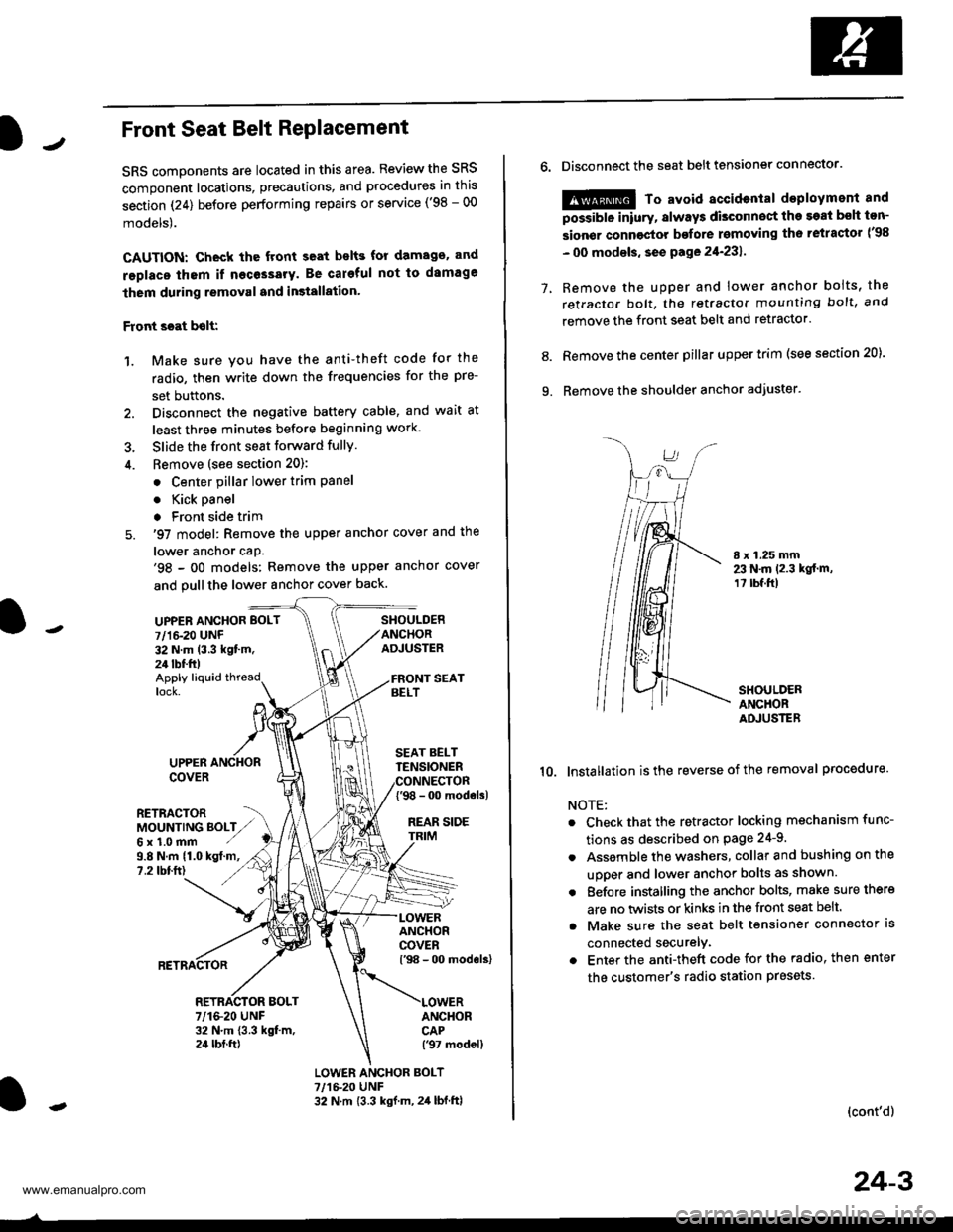
JFront Seat Belt RePlacement
SRS components are located in this area. Review the SRS
component locations, precautions, and procedures in this
section (24) before performing repairs or service ('98 - 00
models).
CAUTION: Check the front seat bslts for damago. and
replaco thom if necessary. Be careful not to damage
them during removal and in3tallation'
Front scat bolt:
1. Make sure you have the anti-theft code for the
radio, then write down the frequencies for the pre-
set buttons.
2. Disconnect the negative battery cable, and wait at
least three minutes before beginning work.
3. Slide the front seat forward fully.
4. Bemove (see section 20):
. Center pillar lower trim Pane
. Kick oanel
. Front side trim
5. '97 model: Remove the upper anchor cover and the
lower anchor caP.'98 - oO models: Remove the upper anchor cover
and pull the lower anchor cover back.
UPPEN ANCHOR BOLT
7/1&20 UNF32 N.m (3.3 kgt'm.24 tbf.ft)
SHOULDERANCHORADJUSTER
Apply liquid threadlock.
9.8 N.m (1.0 kgt.m,?.2 tbtft)
UPPERCOVER
RETRACTORMOUNTING BOLTZ,,Gx1.0mm ./
SEAT BELTTENSIONER
{'98 - 0o modols)
REAR SIDE
ANCHORCOVERl'98 - 00 models)
ANCHORCAP('97 modell
RETRACTOR BOLT7/1&20 UNF32 N.m 13.3 kgt m,24 tbt.ft)
LOWER ANCHOR BOLT?,/1&20 UNF32 N.m {3.3 kgf.m, 2,1 lbf.ftl
o.Disconnect the seat belt tensiongr connector.
@ To avoid accidontal deployment and
possibte inlury, always disconnect the soat bsh ton-
sion€r connoctor bofore rsmoving th6 retractor l'98
- 00 modsls, se€ pa ge 21-231 .
Remove the uDDer and lower anchor boits, the
retractor bolt, the retractor mounting bolt, and
remove the front seat belt and retractor.
Remove the center pillar upper trim (see section 20).
Remove the shoulder anchor adjuster.
7.
9.
8.
I x 1.25 mm23 N.m 12.3 kgt.m,1? tbf.ft)
SHOULDERANCHORADJUSTER
10. lnstallation isthe reverse of the removal procedure.
NOTE:
Check that the retractor locking mechanism func-
tions as described on Page 24-9.
Assemble the washers, collar and bushing on the
uooer and lower anchor bolts as shown.
Eefore installing the anchor bolts, make sure there
are no twists or kinks in the front seat belt.
Make sure the seat belt tensioner connector ls
connected securelv.
Enter the anti-theft code for the radio, then enter
the customer's radio station presets
(cont'd)
24-3
www.emanualpro.com