Page 920 of 1395

Rear Suspension
Hub Bearing Unit Replacement (cont'd)
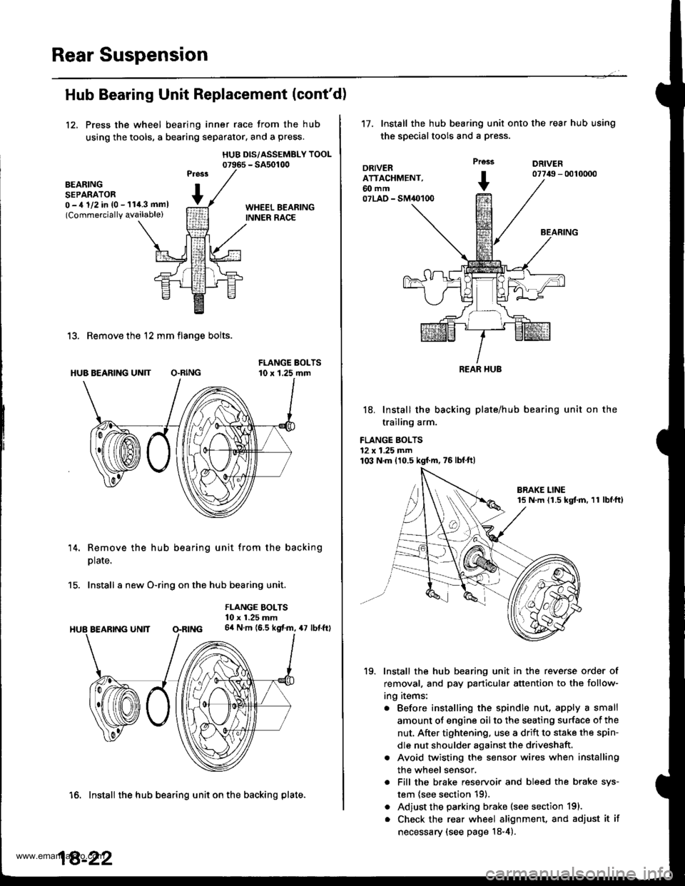
12, Press the wheel bearing inner race from the hub
using the tools, a bearing separator, and a press.
HUB DIS/ASSEMBLY TOOL07965 - SA50100
BEARINGSEPARATOR0 -,t 1/2 in {0 - 11i1.3 mml(Commercially qvailable)
13. Remove the 12 mm flange bolts.
HUB BEARING UN]T O.RING
14. Remove the hub bearing unit from the backing
plate.
15. Install a new O-ring on the hub bearing unit.
FLANGE BOLTS10 x 1.25 mm64 N.m (6.5 kgf.m, 47 lbf.ftl
16. Install the hub bearing unit on the backing plate.
18-22
't7.Install the hub bearing unit onto the rear hub using
the special tools and a press.
DRIVERATTACHMENT,60 mm07LAO - SM40100
Prcss
+
DRIVER07749 - 0010000
BEARING
18. Install the backing plate/hub
trailing arm.
FLANGE BOLTS12 x 1.25 mm103 N.m 110.5 kgf'm,75lbfft)
bearing unit on the
19. Install the hub bearing unit in the reverse order of
removal, and pay particular attention to the follow-
ing items:
. Before installing the spindle nut, apply a small
amount of engine oil to the seating surface of the
nut, After tightening, use a drift to stake the spin-
dle nut shoulder against the driveshaft.
. Avoid twisting the sensor wires when installing
the wheel sensor,
. Fill the brake reservoir and bleed the brake sys-
tem {see section 19).
. Adjust the parking brake (see section 191.
. Check the rear wheel alignment, and adjust it if
necessary (see page 18-4).
REAR HUB
www.emanualpro.com
Page 921 of 1395
Rear Damper
1.
Upper Arm Bushing Replacement
Remove the upper arm bushing and upper arminner bushing as shown.
UPPER ARM INNER BUSHING UPPER ARM AUSHIT{G
Mark a scribe line on the upper arm inner bushing
so it is in line with the bolt mounting surface.
BOLT MOUNTII{GSURFACE
Make a mark on the upper arm at two points so the
marks are in line and at a right angle with the arm
as shown in the drawing.
Drive in the upper arm inner bushing with themarks aligned until the leading edge is flush with
the uoDer arm.
Drive the upper arm bushing into the upper armuntil the leading edge is flush with the upper arm.
REAR UPPER ARM
5.
Removal
Remove the rear wheels (see page '18-21),
Remove the damper access panel and the damper
cap.
Remove the two flange nuts.
ACCESS PANEL
OAMPER CAP
't.
4. Remove the flange bolts.
Lower the rear suspension, and remove
damper.the
1a-23
www.emanualpro.com
Page 922 of 1395

Rear Damper
Disassembly/lnspection
Disassembly
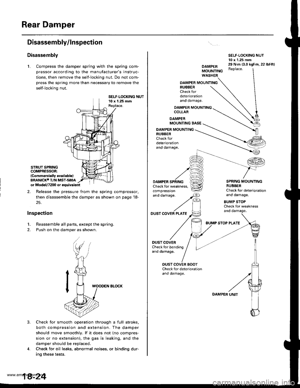
L Compress the damper spring with the spring com-
pressor according to the manufacturer's instruc-
tions, then remove the self-locking nut. Do not com-
press the spring more than necessary to remove the
self-locking nut.
SELF-LOCKING NUT10 x 1.25 mmReplace.
STRUT SPRINGCOMPRESSOR:lCommercirlly avaihblo)BRANICKO I/N MSI-580Aor Mod6l/7200 or equivalent
2. Release the pressure from the spring compressor,
then disassemble the damper as shown on page 18-
25.
Inspection
1. Reassemble all parts, except the spring.
2. Push on the damper as shown.
3.
WOODEN ELOCK
Check for smooth operation through a full stroke,
both compression and extension. The damper
should move smoothly. lf it does not (no compres-
sion or no extension), the gas is leaking, and the
damper should be replaced.
Check for oil leaks, abnormal noises, or binding dur-
ino these tests.
4.
SELF-LOCKING NUT10 x 1.25 mm
OAMPERMOUNTINGWASHER
29 N.m {3.0 kgf.m, 22 lbf.ft)Beplace.
OAMPER MOUNTINGRUBBERCheck fordeteriorationano oamage.
DAMPER MOUNTINGCOLLAR
DAMPERMOUNTING BASE
DAMPER MOUNTINGRUBBERCheck fordeteriorationano oamage.
'"dd"^.s"'
//F,
DAMPERCheck for weakness,compressron
DUST COVER PLATE
DUST COVERCheck for bendingand damage.
SPRING MOUNTINGRUBBERCheck Ior deteriorationand damage.
BUMP STOPCheck for weaknessano oamage.
DUST COVEN BOOTCheck for deterioralionano oamage.
BUMP STOP PLATE
DAMPER
www.emanualpro.com
Page 923 of 1395

Reassembly
1.Install the damper unit on a spring compressor,
Assemble the rear damper in reverse order of disas-
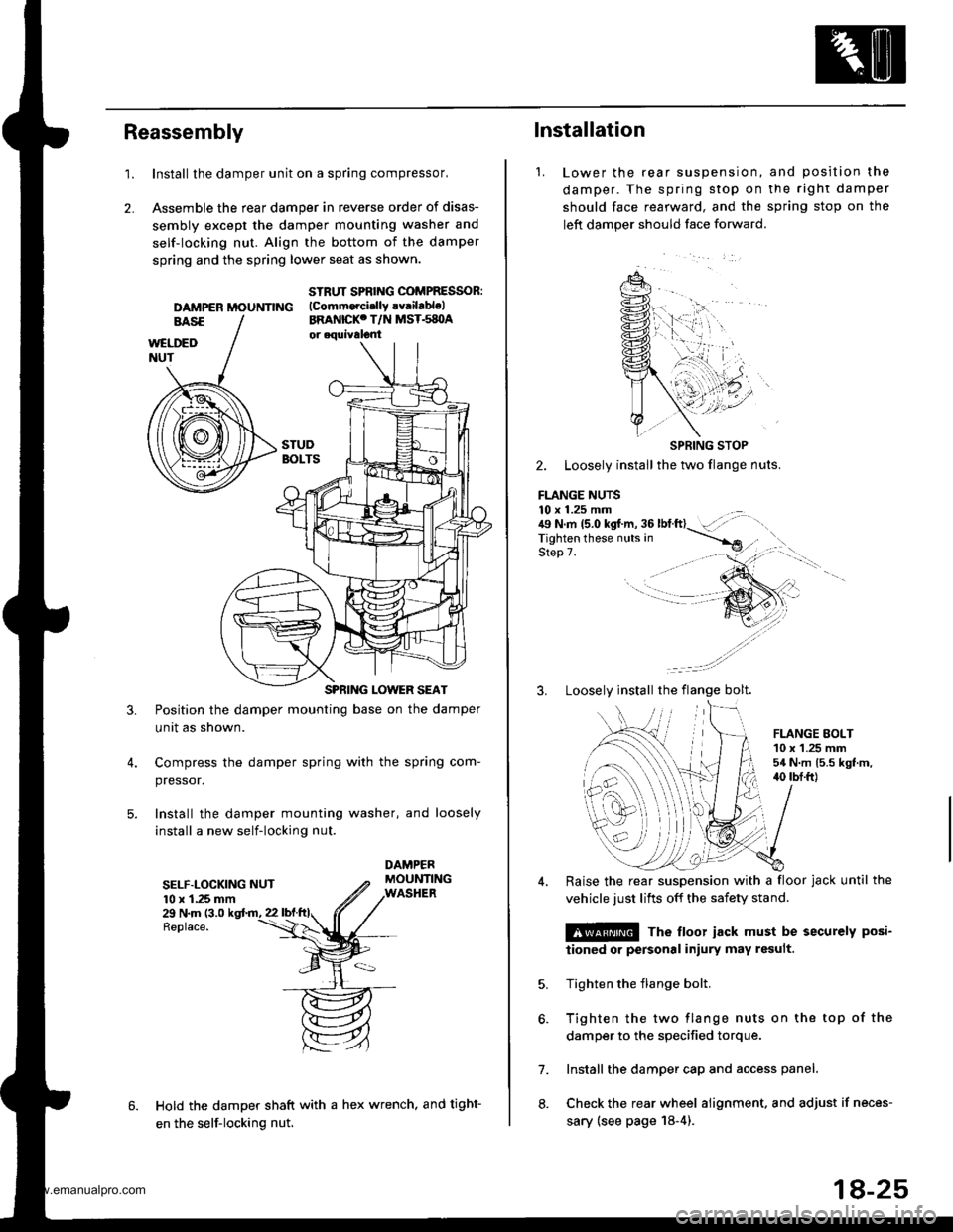
sembly except the damper mounting washer and
self-locking nut. Align the bottom of the damper
spring and the spring lower seat as shown.
2.
DAMPER MOUNNNG
STRUT SPBING COMPRESSOR:(Commorcislly !v.ilablelBRANICKC T/N MST.s8OA
3.Position the damper mounting base on the damper
unit as shown.
Compress the damper spring with the spring com-
pressor.
Install the damper mounting washer, and loosely
install a new self-locking nut.
SELF.LOCKING NUT10 x 1.25 mm29 N.m (3.0
Replace.
Hold the damper shaft with a hex wrench, and tight-
en the self-locking nut.
1.
lnstallation
Lower the rear suspenston,
damper. The spring stop on
should face rearward, and the
left damper should face forward.
and position the
the right damper
sprang stop on the
SPRING STOP
2. Loosely install the two flange nuts.
FLANGE NUTS10 x 1.25 mm . .:{9 N.m 15.0 kgf.m, 36 lbtft}- :',,-rigf't"n if'"""_nrr. in ----.-*
qla^ 7Step 7.
3. Loosely install the flange bolt.
FLANGE EOLT10 x 1.25 mm54 N.m 15.5 kgt.m,40 tbI.ft)
6.
7.
8.
Raise the rear suspension with a floor jack until the
vehicle just lifts off the safety stand.
@ The floor iack must be securely posi-
iioned or personal iniury may result.
Tighten the flange bolt.
Tighten the two flange nuts on the top of the
damper to the specified torque.
Install the damper cap and access panel.
Check the rear wheel alignment. and adjust if neces-
sary (see page 18-4).
18-25
www.emanualpro.com
Page 935 of 1395

Front Brake Disc
Disc Runout Inspection
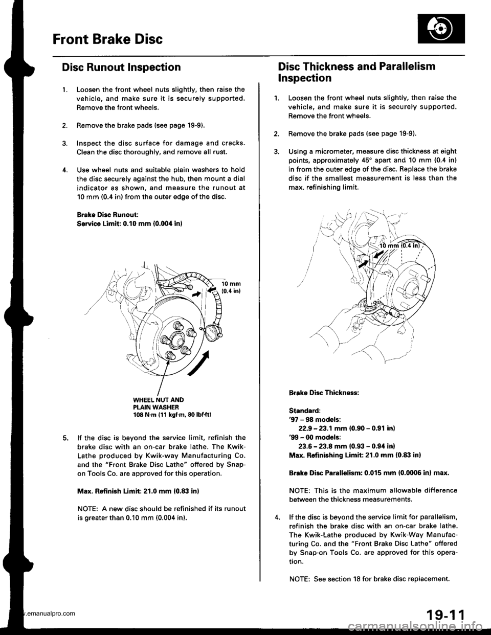
l.Loosen the front wheel nuts slightly, then raise the
vehicle, and make sure it is securely supported.
Remove the front wheels.
Remove the brake pads {see page 19-9).
Inspect the disc surface for damage and cracks.
Clean the disc thoroughly, and remove all .ust.
Use wheel nuts and suitable plain washers to hold
the disc securely against the hub, then mount a dial
indicator as shown, and maasure the runout at
10 mm (0.4 in) from the outer edge of the disc.
Brake Di3c Runout:
Service Limit: 0.10 mm {0.00,0 in)
WHEEL NUT ANDPLAIN WASHER108 N.m {11 kg{ m, 80 lbf.ft)
lf the disc is beyond the service limit, refinish the
brake disc with an on-car brake lathe. The Kwik-
Lathe produced by Kwik-way Manufacturing Co.
and the "Front Brake Disc Lathe" offered by Snap-
on Tools Co. are approved for this operation.
M8x. Rofinish Limit: 21.0 mm l0.8il in)
NOTE: A new disc should bs refinished if its runout
is greater than 0.10 mm (0.004 in).
Disc Thickness and Parallelism
Inspection
1.Loosen the front wheel nuts slightly, then raise the
vehicle, and make sure it is securely supported.
Remove the front wheels.
Remove the brake pads (see page 19-9).
Using a micromater, measure disc thickness at eight
points, approximately 45'apan and 10 mm (0.4 in)
in from the outer edge of the disc. Replace the brake
disc if the smallest measurement is less than the
max. refinishing limit.
Brake Disc Thickness:
Standard:'97 - 98 modsls:
22.9 -23.1mm {0.90 - 0.91 inl'99 - 00 mod€ls:
23.6 - 23.8 mm {0.93 - 0.94 in}
Max. Refinishing Limit:21.0 mm (o.txl in)
Brake Disc Parallelism: 0.015 mm {0.0006 in} max.
NOTE: This is the maximum allowable difference
between the thickness measurements,
lf the disc is beyond the service limit for parallelism,
refinish the brake disc with an on-car brake lathe.
The Kwik-Lathe produced by Kwik-Way Manufac-
turing Co. and the "Front Brake Disc Lathe" offered
by Snap-on Tools Co. are approved for this opera-
tron.
NOTE: See section 18 for brake disc replacement.
19-1 1
www.emanualpro.com
Page 937 of 1395

Master Cylinder/Brake Booster
Removal/lnstallation
1, Disconnect the brake fluid level switch connectors.
2. Remove the reservoir cap from the master cylinder.
3. Remove the brake fluid from the master cvlinder
reservoir with a syringe.
4. Disconnect the brake lines from the master cylinder.
To prevent spills, cover the line joints with rags or
shop towels.
5. Remove the master cylinder mounting nuts and
wasners.
6. Remove the master cylinder from the brake booster.
CAUTION: Be careful not to bend or damage the
brake lines when removing the master cylinder.
Do not spill brake fluid on the vehicle; it may dam.
age the paint; it brake fluid does cont.ct the paint,
wash it oft immediately with water.
7. Disconnect the vacuum hose from the brake booster.
8. Remove the cotter pin and clevis pin from the clevis.
Do not disconnect the clevis by removing it from
the operating rod of the brake booster. lf the clevis
is loosened, adjust the pushrod length before
installing the brake booster (see page 19-15).
To Front Caliper (Without ABS)
\\
15 N.m {1.5 kgtm, vAcuuM HosE
r r rbf.ft) |
/ | BRAKE FLUTD LEvEL
/l /
swrrcHcoNNEcroRs
/ I I I COTTER PIN
I I / neotace
l,/-- ro Rear wheet cylinders / | I
h ./-''' /. I I IYli //*s (.S
I /r:
9. Remove the four booster mounting nuts.'10. Pull the brake booster forward until the clevis is
clear of the bulkhead.
11. Remove the brake booster from the enqine com-
panment.
12. Install the brake booster and master cylinder in the
reverse order of removal, and note these items:
. When connecting the brake lines, make sure that
there is no interference between the brake lines
and other parts.
. Be careful not to bend or damage the brake lines
when installing the master cylinder.
. lf replacing the master cylinder or brake booster,
check and adjust the pushrod clearance before
installing the master cylinder (see page 19-14).
Fill the master cylinder reservoir, and bleed the
brake system (see page 19-7).
After installation, check the brake pedal height and
brake pedal free play (see page 19-5), and adjust if
necessary.
13 N.m 11.3 kg{.m,I rbf.ft)
13.
14.
To Master Cylinder(Without ABS)To Modulator Unit(with ABs)@-\
\
^ To Front Caliper
9i\.
-#qCLEVIS PIN
):-,/
PROPORTIONING CONTROL VALVE
MASTER CYLINDER
15 N.m (1.5 kgf.m, 11 lbl.ftl
BRAXE BOOSTER
www.emanualpro.com
Page 983 of 1395
Doors
Component Location Index
Front Door:
NOTE: Refertothe 1997 Series Honda CR-V Body Repair Manual (P/N 61S1030) forfrontdoor removat.
ffi
*Y
lPOWER DOOR LOCKCONTROL UNIT
t\q
efl-Nr2
/ *-8
ARMREST
OOOR CHANNEL TAPE
INNERW€ATHERSTRIP
v
MIRROR MOUNTCOVER
----s-re
"\-,-.*
€fl
FRONT DOORPosition Adjustment,page 20-22
FRONT DOOR PANELRemoval and lnstallation, page 20,7
OUTER MOLDING
PLASTICCOVER
,.r=R
\//
::r
HINGE
20-2
www.emanualpro.com
Page 1002 of 1395
a,
o.
c.
o.
6x1.0mm8 N'm 10 8 kg{ m'6 tbf.ftl
Raise the glass fully.
Loosen the regulator mounting bolts.
Push the glass forward.
Tighten the regulator mounting bolts.
>: Boh locations, il
6x1.0mm8 N.m (0.8 kgf.m, 6 lbf.ft)
GLASS
Loosen the rear channel mounting bolts,
Lower the glass.
Push the rear channel against the glass, then
tighten the mounting bolts.
>: Boh locationt 25x1.0mm8 N.m (0.8 kgt m.6lbtft)
3. Check that the glass moves smoothly.
4. Raise the glass fully and check for gaps.
5. Check the glass operation.
NOTE: Check that the glass contacts the glass run
channel evenly.
f.
GLASS
20-21
www.emanualpro.com