Page 806 of 1395
Rear Differential Assembly
Removal/lnstallation
l!!@ Make sure tifts are ptaced property lseesection 11.
1. Drain the differential flujd (see page 15-14).
2. Mark the propeller shaft and companion flange of
the rear differential assembly so they can be rein-
stalled in their original positions.
PROPELLER SHAFTCOMPA'{ION FLANGE
Remove the propeller shaft from the rear differential
assemory.
Remove the rear differential damper.
12 POtt'lT BOLI8 x 1.25 mm32 N.m 13.3 tgf.m. 2a lbtft,
Mark
12 x 1.25 mm
15-16
5,1 N.m 15,5 kgf.m, iO tbf.fO
5, Place a transmission jack under the rear differential
assembly, then remove the right mounting bracket B
and the left mounting bracket 8.
Remove the breather tube from the breather tubefitting.
BREATHER TUBE flTNNG
www.emanualpro.com
Page 807 of 1395

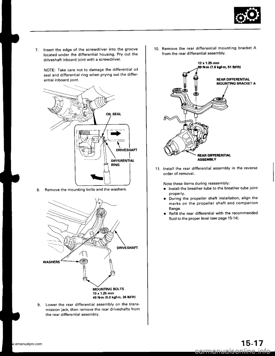
7. Insert the edge of the screwdriver into the groove
located under the differential housing Pry out the
driveshaft inboard ioint with a screwdraver.
NOTE: Take care not to damage the differential oil
seal and differential ring when prying out the differ-
ential inboard joint.
8. Remove the mounting bolts and the washers.
DRIVESHAFT
MOUNTING BOLTS'10 x 1 .25 mm,19 N'm (5 0 kgf m, 36 lbtftl
Lower the rear differential assembly on the trans-
mission jack, then remove the rear driveshafts from
the rea r difterential assembly.
DIFFERENTIAL
12 x 1.25 fifi
10. Remove the rear difterential mounting bracket A
from the rear differential assembly.
N.m {7.0 lgf.m. 5l lbl.tt)
REAR DIFFERENTIALMOUNTING BRACKET A
REAN DFFERENTI,ALASSEMBLY
11.Install the rear differential assembly in the reverse
order of removal.
Note these items during reassembly
. lnstall the breather tube to the breather tube joint
properly.
. During the propeller shaft installation, align the
marks on the propeller shaft and companion
flange.
. Reiill the rear differential with the recommended
fluid to the proper level {see page 15-14).
15-17
www.emanualpro.com
Page 813 of 1395
Reassembly
1. Apply CVT fluid to the rubber of the oil strainer, then
install the oil strainer, the magnet, and the oil pump
pin to the differential carrier.
OIL PUMP PIN
DIFFERE]TTIAL CARRIERASSEMBLY
Align the oil pump pin with the groove of the rear oil
pump in the pump body assembly, then install the oil
pump body assembly to the differential carrier assem-
oty.
-n
CWfluid
2.
MAGNET
OIL PUMP BODY ASSEMBLY
3. Tighten the oil pump body assembly mounting
bolts.
4. Install the oil pump driveshaft by aligning the pro-
jection of the oil pump driveshaft with the groove of
the front oil pump in the oil pump body assembly.
lnstall in this direction.
Projection
6x1.0mm12 N.m 11.2 kg{.m,8.7 lbl.ft}
Install the thrust needle bearing.
Install the pressure plate assembly by aligning the
projection of the pressure plate with the groove of
the oil pump driveshaft.
5.
OIL PUMPDRIVESHAFT
(cont'd )
15-23
THRUST NEEDLE BEABING
PRESSURE PLATE
www.emanualpro.com
Page 837 of 1395

Rear Driveshafts
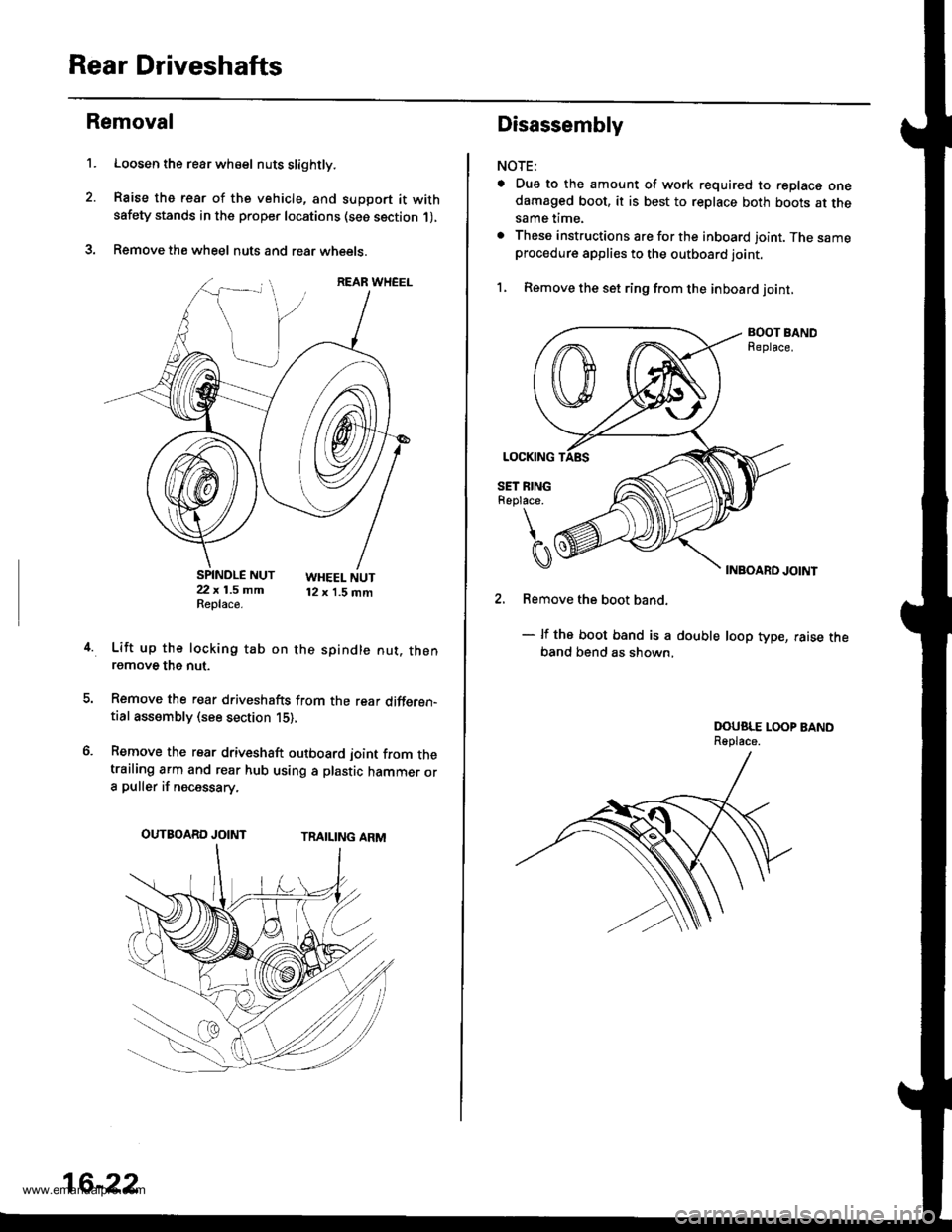
't.
Removal
Loosen the rear wh€el nuts slightly.
Raise the rear of the vehicle, and support it withsafety stands in the proper locations (see section 1),
Remove the wheel nuts and rear wheets.
SPINDLE NUT22 x 1.5 mmReplace.
WHEEL NUT12 x 1.5 mm
4.Lift up the locking tab on the spindle nut. thenremove the nut.
Remove the rear driveshafts from the rear differen-tial assembly (see section 15),
Remove the rear driveshaft outboard joint from thetrailing arm and rear hub using a plastic hammer ora puller if necessary.
TRAILING ARMOUTBOARD JOINT
16-22
Disassembly
NOTE:
a Due to the amount of work required to replace onedamaged boot, it is best to replace both boots at thesame time.
. These instructions are for the inboard joint. The sameprocedure applies to the outboard joint.
1, Remove the set ring from the inboard joint,
BOOT BANDReplace.
INBOARD JOINT
2. Remove the boot band.
- lf the boot band is a double loop type, raise theband bend as shown,
DOUSLE LOOP BANDReplace.
www.emanualpro.com
Page 843 of 1395
Rear Driveshafts
Reassembly (cont'd)
18. Install the new set ring into the driveshaft groove.
SET RINGReplace.
I
CI
SET RING GROOVE
16-2A
lnstallation
'1. lnstall the outboard joint into the trailing arm.
Install the rear driveshafts into the rear differential
assembly (see section 15).
Apply a small amount of engine oil to the seating
surface of the new spindle nut.
SPINDLE NUT 22 x 1.5 mm181 N.m (18.5 kgf.m, 134lbl.ftl Replace.
Install a new spindle nut, then torque the nut. After
tightening, use a drift to stake the spindle nut shoulder
against the driveshaft.
Clean the mating surfaces of the brake disc and the
wheel, then install the rear wheel, and torque the
wheel nuts.
WHEEL NUT 12 x 1.5 mm108 N.m (11.0 kgt.m, 80lbtftl
www.emanualpro.com
Page 845 of 1395

Propeller Shaft
RemovaUlnstallation
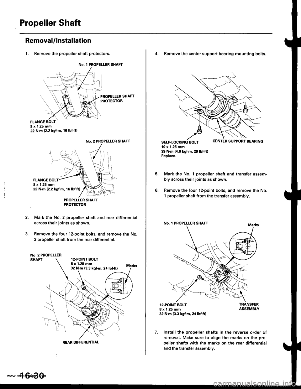
1, Remove the propeller shaft protectors.
No. 1 PROPELLER SHAFT
PROPELLER SHAFTPROTECTOR
FLANGE BOLTI x 1 .25 mm22 N.m (2.2 kg{.m. 16lbl'ft)
2.
No. 2 PROPELLER SHAFT
FLANGE BOLT8 x 1.25 mm22 N.m 12.2 kgf.m, 16lbf.ft)
PNOPELLER SHAFTPROTECTOR
Mark the No. 2 propeller shaft and rear differsntial
across their joints as shown.
Remove the four 12-point bolts. and remove the No.
2 propeller shaft from the rear differential.
No.2 PROPELLERSHAFT12.POINT BOLT8 x 1.25 mm32 N.m 13.3 kst m, 24 lbtftl
REAR DIFFERENTIAL
16-30
4, Remove the center support bearing mounting bolts.
SELF-LOCK|NG BOLT uErr rEn Durrr.r'r I I'EAnrNu
10 x 1.25 mm39 N'm 14.0 kg{.rn,29 lbtftlReplace.
Mark the No. I propeller shaft and transfer assem-
bly across their joints as shown.
Remove the four 12-point bolts, and remove the No.
1 propeller shaft from the transfer assembly,
No. 'l PROPELLER SHAFT
o.
12.POINT BOLT8 x 1.25 mm32 N.m 13.3 kgt'm, 2,1 lbf.ft)
TRANSFERASSEMBLY
7. Install the propeller shafts in the reverse order of
removal. Make sure to align the marks on the pro-
p€ller shafts with the marks on the rear differential
and the transfer assemblv.
www.emanualpro.com
Page 858 of 1395
Steering Linkage and Gearbox
PINION SHAFT GROMMETInspoct for damage and deterioration.
STEERING JOINTSCheck for loose joint bolts.
NE-ROD LOCKNUTCheck Ior loose locknut.
Inspect for loose mounting bolts.GEARBOX MOUNTING CUSHIONSlnsp6ct for dgterioration.BOOTlnspect for damag€ and d€terioration.
BALL JONT AOOTInspoct lor damage and deterioration.S€e page 17-50 for replacemont.
END AAtL JOINTInspect for faulty movementano oamag€.
17-13
www.emanualpro.com
Page 859 of 1395

Inspection and Adjustment
Pump Belt
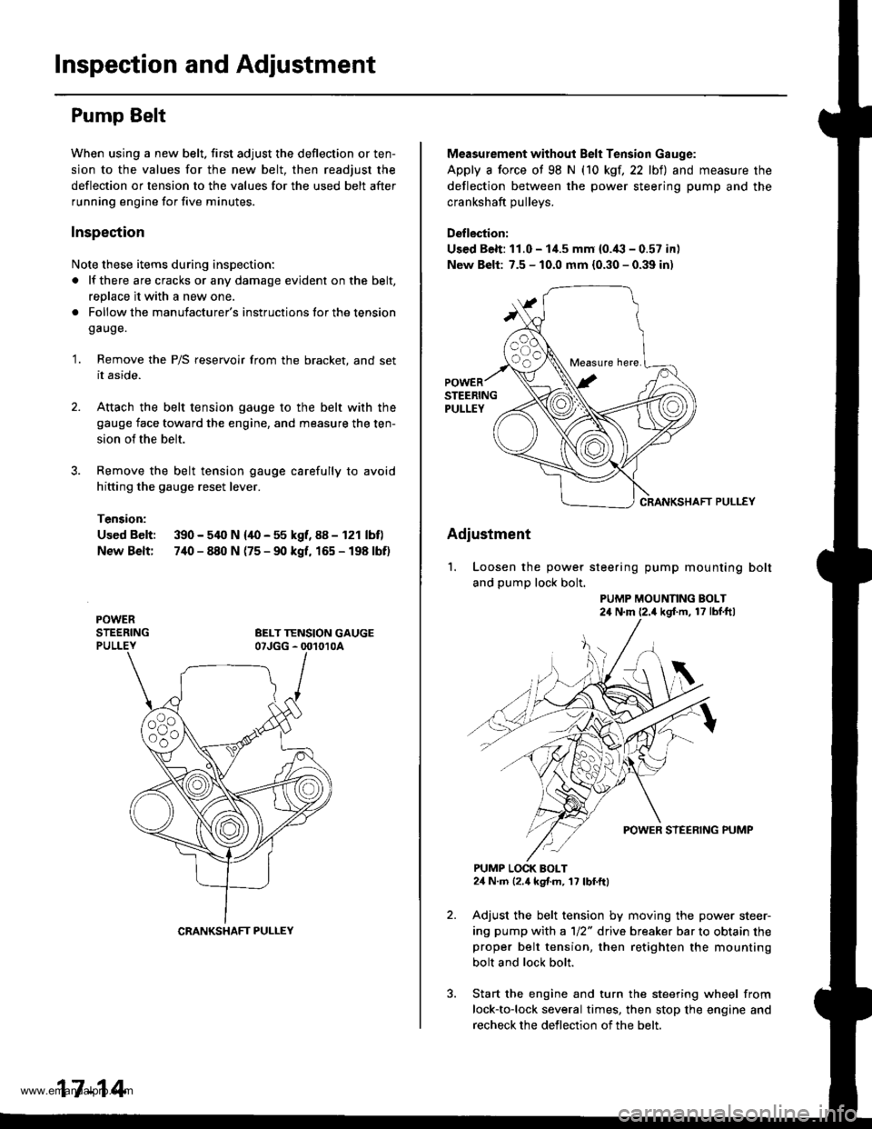
When using a new belt. first adjust the deflection or ten-
sion to the values for the new belt, then readjust the
deflection or tension to the values for the used belt after
running engine for five minutes.
Inspection
Note these items during inspection:
a lf there are cracks or any damage evident on the belt,
replace it with a new one.
. Follow the manufacturer's instructions lor the tension
gauge.
'1. Remove the P/S reservoir from the bracket, and set
it aside.
2. Attach the belt tension gauge to the belt with the
gauge face toward the engine, and measure the ten-
sion of the belt.
Remove the belt tension gauge carefully to avoid
hitting the gauge reset lever.
Tension:
Used Belt: 390 - 540 N {40 - 55 kgf, 88 - 121 lbf)
New Belt: 7,[0 - 840 N (75 - 90 kgf, 165 - 198 lbf)
CRANKSHAFT PULLEY
17-14
Measurement without Belt Tension Gauge:
Apply a force ot 98 N (10 kgf,22 lbt) and measure the
deflection between the power steering pump and the
crankshaft oullevs.
Deflection:
Used Belt: 11.0 - 1i1.5 mm {0.'(l - 0.57 in)
New Belt: 7.5 - 10.0 mm {0.30 - 0.39 in)
CRANKSHAFT PULLEY
Adiustment
'1. Loosen the power steering pump mounting bolt
and pump lock bolt.
PUMP MOUNNNG BOLT24 N'm (2.4 kgf'm, 17 lbf ftl
PUMP LOCK BOLT24 N.m 12.4 kgf.m, 17 lbf.ftl
Adjust the belt tension by moving the power steer-
ing pump with a 1/2" drive breaker bar to obtain theproper belt tension, then retighten the mounting
bolt and lock bolt.
Start the engine and turn the steering wheel from
lock-to-lock several times, then stop the engine and
recheck the deflection of the belt.
Measure here.
www.emanualpro.com