Page 103 of 1395

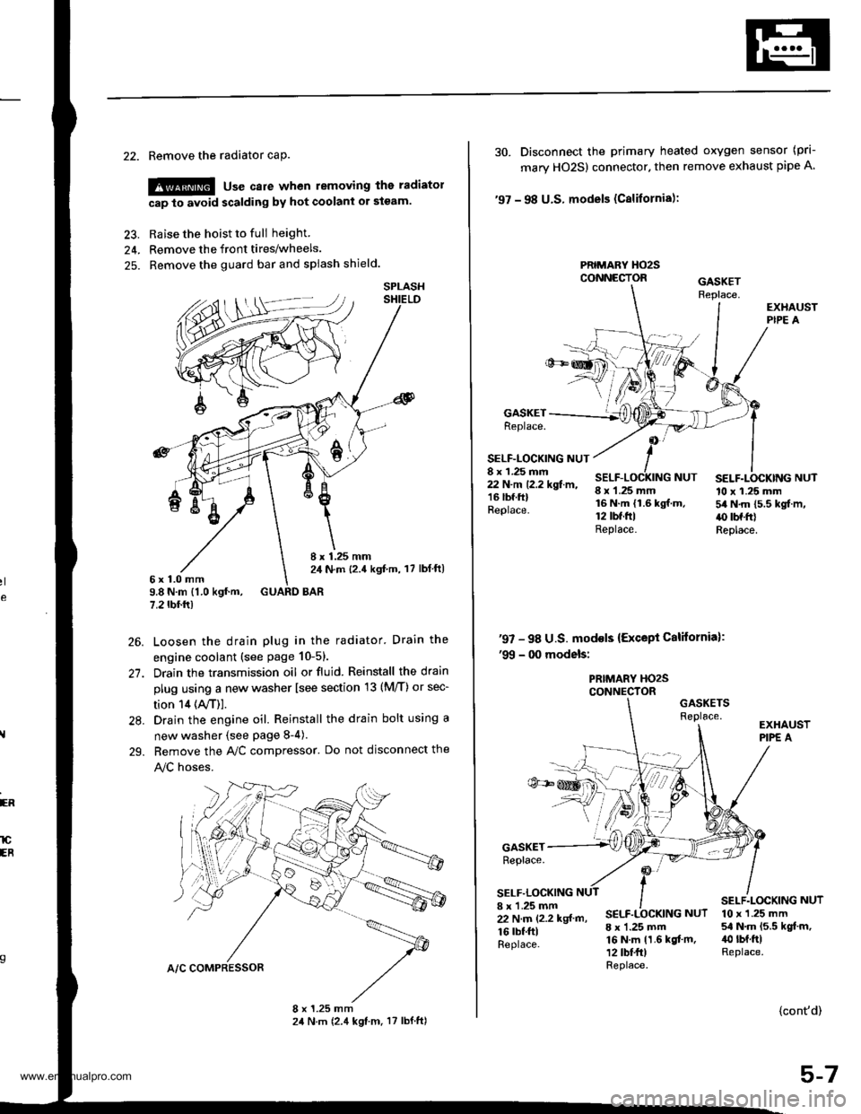
22. Remove the radiator caP.
!@ use care when removing the radiatol
cap to avoid scalding by hot coolani or steam.
23. Raise the hoist to full height
24. Remove the front tires/wheels.
25. Remove the guard bar and splash shield.
8 x 1.25 mm2,1 N.m {2.4 kgf,m, 17 lbl ft)6x1.0mm9.8 N.m {1.0 kgf.m, GUARD BAR7.2 tbf.rr)
Loosen the drain plug in the radiator. Drain the
engine coolant (see page 10-51.
Drain the transmission oil or fluid. Reinstall the drain
plug using a new washer lsee section 13 (M/T) or sec-
tion 14 (ly'T)].
Drain the engine oil. Reinstall the drain bolt using a
new washer {see page 8-4).
Bemove the A,/C compressor. Do not disconnect the
!y'C hoses.
SPLASH
26.
27.
28.
29.
ER
lCEB
30. Disconnect the primary heated oxygen sensor (prl-
mary HO2S) connector. then remove exhaust pipe A
'97 - 98 U.S. models (Cslifornia):
PRIMARY HO2SCONNECTOR
GASKETReplace.
SELF-LOCKING NUT8 x 1.25 mm22 N.m 12.2 kgf.m,16 lbf.ftlReplace.
8 x 1.25 mm16 N.m {1.6 kgf.m.12 tbt.ftlReplace.
SELF.LOCKING NUT10 x 1.25 mm54 N.m 15.5 kgf.m,.() tbf.frlReplace.
NUT
'97 - 98 U.S. mod€ls {Except California):'99 - 00 models:
PRIMARY HO2SCONNECTORGASKETSReplace.
GASKETReplace.
SELF.LOCKING8 x 'l.25 mm22 N.m (2.2 kgf m,
16 rbf.ftlReplace.
SELF.LOCKING NUT
8 x 1.25 mm16 N.m 11.6 kgf.m,12 tbt fr)Replace.
10 x 1.25 mm54 N.m 15.5 kgt.m,40 rbt.ftlReplace.
{cont'd)
5-7
www.emanualpro.com
Page 681 of 1395
Transfer Assembly
Removal
@ Make sure the lifts, iacks, and safety
stands are placed properly (see section 11.
1. Raise the front of the vehicle, and make sure it is
supported securely.
2. Set the parking brake, and block both rear wheels
securelv.
3 Drain the automatic transmission fluid (ATF).
Reinstall the drain plug with a new sealing washer'
DRAIN PLUG'18 x'1.5 rnm49 N.m 15.0 kgf.m, 36 lbl.ftl
4. Remove the guard bar and the splash shield.
GUARD 8AR
14-165
5.Disconnect the primary heated oxygen sensor
{Primary HO2S) connector.
Remove exhaust pipe A.
SELF-LOCKINGNUTBeplace.
7.
SEI-F.LOCKINGNUTReplace.
NUTReplace
Remove the shift cable cover.
Remove the snap pin and control pin, then separate
the shift cable from the control lever. Do not bend
the shift cable excessively.
(cont'd)
www.emanualpro.com
Page 819 of 1395

Front Driveshafts
Removal (cont'd)
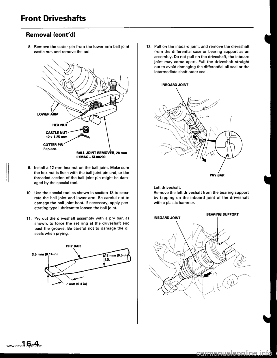
Remove the cotter pin from the lower arm ball ioint
castle nut, and remove the nut.
Install a 12 mm hex nut on the ball joint. Make sure
the hex nut is flush with the ball joint pin end, or the
threaded section of the ball joint pin might be dam-
aged by the special tool.
Use the special tool as shown in section '18 to sepa-
rate the ball joint and lower arm, Be caretul not to
damage the ball joint boot, lf necessary, apply pen-
etrating type lubricant to loosen the ball joint,
Pry out the driveshaft assembly with a pry bar, as
shown, to force the set ring at the driveshaft end
past the groove. Be careful not to damage the oil
seals when prying.
i0.
1l.
07MAC - SLm2m
PRY BAR
16-4
12. Pull on the inboard joint, and remove the driveshaft
from the differential case or bearing support as an
assembly. Do not pull on the driveshaft, the inboardjoint may come apart. Pull the driveshaft straight
out to avoid damaging the differential oil seal or the
intermediate shaft outer seal.
Left driveshaft:
Remove the left driveshaft from the bearing suppon
by tapping on the inboard joint of the driveshaft
with a olastic hammer.
BEARING SUPPORT
www.emanualpro.com
Page 901 of 1395
Component Locations
Front Suspension:
Rear Suspension:
STABILIZER BAR
REAR OAMPER
LOWER ARM
STABILIZER BAR
LOWER ARM
UPPER ARM
COMPENSATOB ARM
TRAILING ARM
18-3
www.emanualpro.com
Page 906 of 1395

Front Suspension
Suspension Arms Replacement
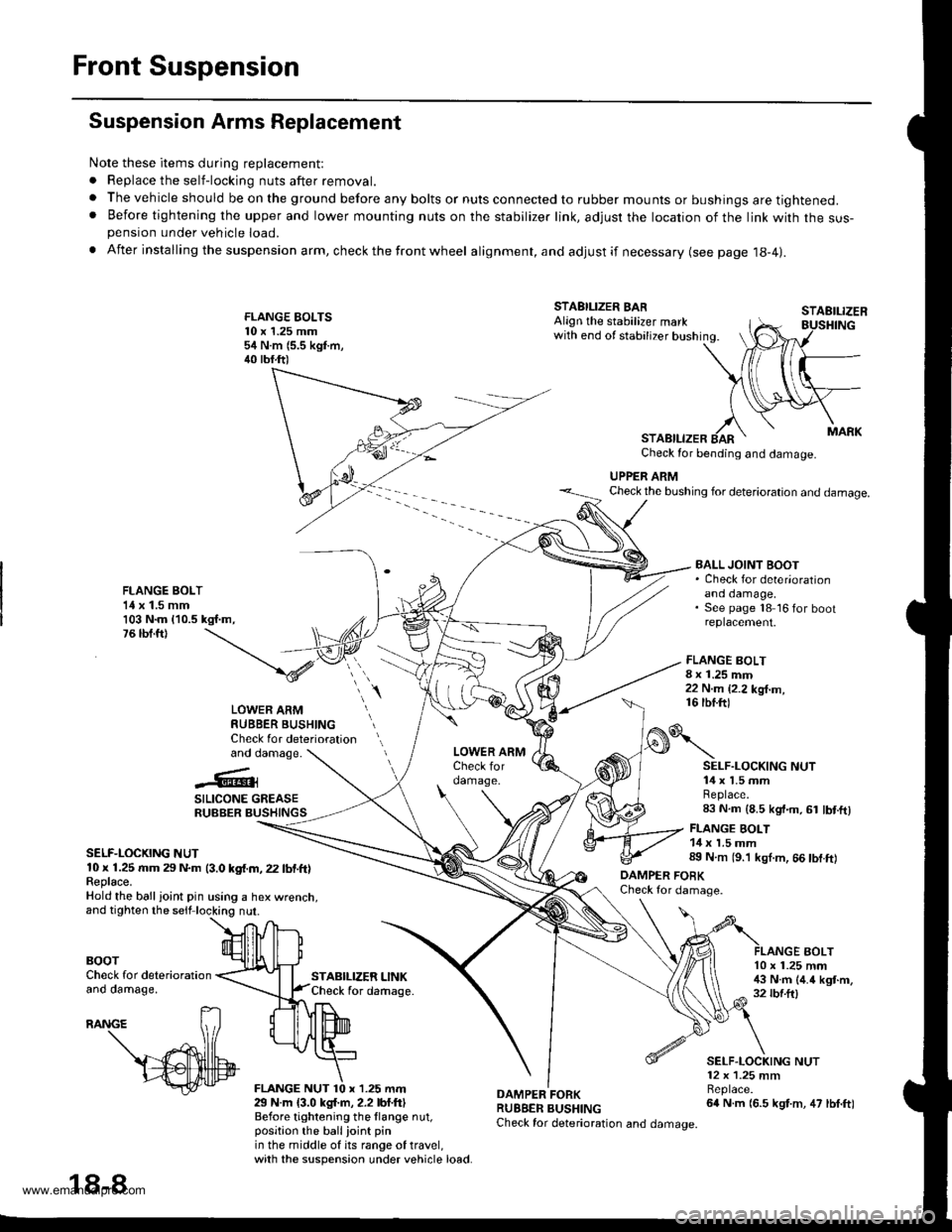
Note these items during replacement:
. Replace the self-locking nuts after removal.
. The vehicle should be on the ground before any bolts or nuts connected to rubber mounts or bushings are tightened.. Before tightening the upper and lower mounting nuts on the stabilizer link, adjusr the location of the link with the sus-pension under vehicle load.
. After insta lling the suspension arm, check the front wheel alignment, and adjust if necessary (see page 18-4|.
FLANGE EOLTS10 x 1.25 mm54 N.m (5.5 kgf.m,40 tbf.ft)
STABILIZER LINKCheck for daftage.
FLANGE BOLT8 x 1.25 mm22 N.m {2.2 kg{.m,16 tbf.ftl
STAEILIZER
AOLT
STABILIZER BARAlign the stabilizer markwith end of stabilizer bushing.
STABILIZERCheck for bending and damage.
UPPER ARMCheck the bushing for deterioration and damage.
FLANGE BOLT1{ x 1.5 mm103 N.m {10.5 kgf.m,76 tbf.ft)
BALL JOINT BOOT. Check for deter'orationano oamage,See page 18 16 for bootreplacement.
LOWER ARMRUBBER BUSHINGCheck for deteriorationand damage.
..'.{l@3
SILICONE GREASERUBBER BUSHINGS
SELF-LOCKING NUT10 x 1.25 rr|m 29 N.m (3.0 kgf.m, 22 lbf.ft)Feplace.Hold the ball ioint pin using a hex wrenct
BOOTCheck for deteriorationano oamage,
29 N.m {3.0 kgl.m, 2.2 lbf.ftlBefore tightening the llange nut,position the ballioint pinin the middle of its range of travel,with the suspension under vehicle load.
DAMPER FORKRUBBER BUSHINGCheck for deterioration and damage.
o\
DAMPER FOBKCheck for damage.
SELF.LOCKING NUT14 x 1.5 mmReplace.83 N.m (8.5 kgt.m, 61 lbt.ftl
FLANGE BOLT14 x 1.5 mm89 N.m (9.'l kgl.m, 66 tbf.ft)
10 x 1.25 mm!$ N.m (4.4 kgt.m,32 rbf.ftl
SELF.LOCKING NUT12 x 1.25 mmBeplace.64 N.m (6.5 kgt.m, 47 lbf.ft)
18-8
www.emanualpro.com
Page 1039 of 1395
Seats
Front Seat Disassembly and Reassembly
CAUTION: When prying with a flat-tip screwdriver, wrap it with protsqtive tape to prevent damage.
NOTE: Take care not to scratch the bodv or tear the seat covers.
Driver's seat lmanually adiustable with manual height adiustmentl:
>: Clio locations Torsion bar removal:Torsion bar removal:
SEAT CUSHION
10 x 1.25 mm,17 N.m (,1.8 kgt m,35 tbt.ft)
PIVOT NUT8 x 1.25 mm22 N.n 12.2 kgl.m,16 rbI.ft)
10 x 1.25 mm47 N.m (4.8 kgf.m,35 tbtfr)
10 x 1 .25 mm47 N.m {,1.8 kgl.m.35 rbt.ft)
20-58
HOOK
HOOKS
www.emanualpro.com
Page 1054 of 1395
A>, 5 V.2
>: Clip locationsA>, 5 B>.3
lf necessary, remove the front bumper beam, front bumper upper beam and guard bar.
>: Boh locationsc>.6D>,2E>,6
TIE DOWNHOOK
Yl- r
{to/
Installation is the reverse ot the removal procedure.
NOTE:
. Make sure the front bumper engages the front
bumper upper beam securely.
. It necessary, adjust the front bumper upper beam
to obtain the proper gap.
. lf necessary, replace any damaged clips.
Gfu @p;i,li',ll-"-'
TIE.DOWNHOOK
v1
10 x 1.25 mm38 N.rn {3.9 kgf.m,28 rbl.ftl
@,,2
nln-nlznr I
dE6 I #\Er+ | ;lHl= |€ =.=r t:Wl
BEAM
FRONT BUMPEB
20-73
www.emanualpro.com
Page 1067 of 1395

Moldings
Door Moldings Replacement (cont'd)
It the old molding is to be reinstalled:
The following materials and tools are required to repair
the molding.
NOTE: Followthe manufacturer's instructions.
Materials: (Reference)
. Stripe remover
3M 08907
. Stripe adhesive remover
3M 08908
. Adhesive tape
3M Super Automotive Attachment Tape
Tools:
. Protective tape
. Knife or Cutter
. Sponge or Shop towel
. Infrared dryer
. Film
. Plastic putty knife
. Alcohol
CAUTION: Put on gloves to protect your hands,
1. lf necessary, replace any damaged clips on the mold-
ang.
2. Apply the stripe remover evenly to the bonding sur-
face of the body and molding.
3. Cover the bonding surface of the body and molding
with a film, then heat to 104 - 122"F (40 - 50'C) for 5- 10 minutes with an infrared dryer.
NOTE: Use care when heating to prevent deforma-
tion of the body and molding.
4. Carefully scrape the adhesive tape with a plastic
putty knife.
For removal of adhesive tape residue, follow-up with
stripe adhesive remover, then scrape the adhesive
tape with a plastic putty knife.
Remove the protective tape, then clean the bonding
surface with a sponge dampened in alcohol.
NOTE: Make sure the bonding surface is kept free or
water, oil and grease.
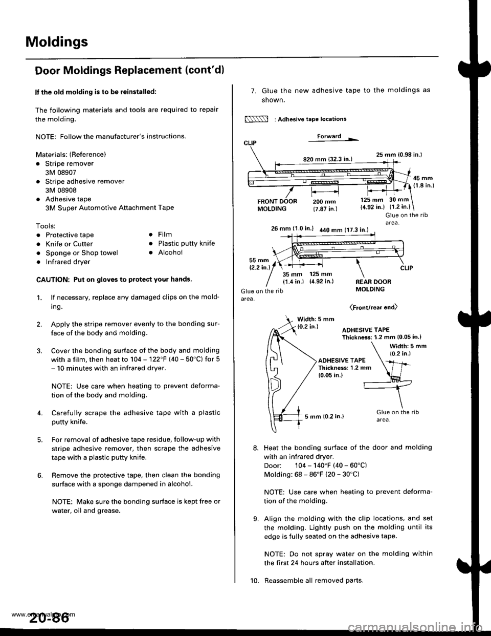
7. Glue the new adhesive tape
snown,
N : Adlesive tape locations
Forwerd L
820 mm 132.3 in.)
FRONTMOLDING
to the moldings as
25 mm {0.98 in.l
45 mm(1.8 in.l
200 mm(7.87 in.)
125 mm
{4.92 in.)30 mm
{1.2 in.}
t'.
Glue on the ribarea,26 mm (1.0 in.) 440 mm 117.3 in.l
35 mm 125 mm
{1.4 in.) {4.92 in.)REAR DOORMOLDING
(Front/rear end)
Width: 5 mm
Heat the bonding surface of the door and molding
with an infrared dryer.
Door: 104 - 140'F (40 - 60'C)
Molding: 68 - 86'F (20 - 30'C)
NOTE: Use care when heating to prevent deforma-
tion of the molding.
Align the molding with the clip locations, and set
the molding. Lightly push on the molding until its
edge is fully seated on the adhesive tape.
NOTE: Oo not spray water on the molding within
the first 24 hours after installation.
Reassemble all removed parts.10.
www.emanualpro.com