1999 HONDA CR-V Drive
[x] Cancel search: DrivePage 556 of 1395
Description
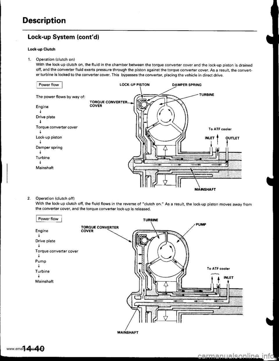
Lock-up System (cont'dl
Lock-up Clutch
L Ooeration (clutch on)
With the lock-up clutch on, the fluid in the chamber between the torque convener cover and the lock-uD oiston is drainedoff, and the converter fluid exerts pressure through the piston against the torque converter cover, As a result, the conven-er turbine is locked to the converter cover. This bipasses the converter, placing the vehicle in direct drive.
LOCK,UP PISTON
The power flows by way of:
Engine
+
Drive plate
Torque converter cover
I
Lock-up piston
t
Damper spring
{
Turbine
Mainshaft
IOROUECOVER
Operation (clutch off)
With the lock-up clutch off, the fluid flows in the reverse of "clutch on." As a result, the lock-up piston moves away fromthe converter cover, and the torque converter lock-up is released.
Engine
I
Drive plate
{
Torque converter cover
{
Pump
I
Turbine
{
Mainshaft
TOROUECOVER
To ATF cooler{(1\\n1INLET
t
Jtl
ort
MAIf{SHAFT
MAII{SHAFT
14-40
www.emanualpro.com
Page 570 of 1395

PCM Terminal Voltage/Measuring Conditions
A/T Control System -'98 - 00 Models
The PCM terminal voltage and measuring conditions are shown for the connector terminals that are related to the A"/T con-
trol system. The other PCM terminal voltage and measuring conditions are described in section 11.
FCM Connector Terminal Localions
NOTE: 819 and C3 terminalsare applied to'99 - 00 models.
o (16Pt
T6rminal NumberSignalDescriptionMeasuring Conditions/Terminal Voltage
A5CRSDownshift signal input from
cruise control unit
When cruise control is used; Pulsing signal
A10scsTiming and adjustment service
check signal (5 V from PCM)
With ignition switch ON (ll) and service check
connector open:5 V
With ignition switch ON (ll) and service check
connector jumped with special tool: 0 V
A14('98 model)
D4 INDD4 indicator light control
{Voltage from PCM turns D4 light
oN)
When ignition switch is first turned ON (ll):
Battery voltage for two seconds
In E position: Battery voltage
A14
('99 - 00 models)
D INDD indicator light control(Voltage from PCM turns D light
oN)
When ignition switch is first turned ON (ll):
Baftery voltage for two seconds
ln E position: Battery voltage
428ILUInterlock control(Voltage from PCM)
When ignition switch ON {ll), brake pedal
depressed, and accelerator pedal released:
Battery voltage
A.32STOP SWBrake switch signal inputBrake pedal pressed; Battery voltage
Brake pedal released: 0 V
FCM CONNECTOR B I25P}
Terminal NumberSignalDescriptionMeasuring Conditions/Terminal Voltage
B1IGPlPower supply circuit from main
relay via under-hood Fuse 44
With ignition switch ON {ll): Battery voltage
With ignition switch OFF: 0 V
82PG1Ground (G101)
B8LSMLinear solenoid power supply
negative electrode
IG P2Power supply circuit from main
relay
With ignition switch ON (ll): Baftery voltage
With ignition switch OFF: 0 V
810PG2Ground (G101)
B17Linear solenoid power supply
positive electrode
With ignition switch ON (ll): Pulsing signal
819
('99 - 00 models)
O/D INDOver-Drive (O/D) OFF indicator
light control
When ignition switch is first turned ON (ll):
0 V for two seconds
O/D OFF indicator light ON:0 V
O/D OFF indicator light OFF: Battery voltage
s20Ground (G101)
B�21VBUBack-up power supply(under-hood Fuse 47)
Always battery voltage
B�22LG2Ground (G101)
14-54
www.emanualpro.com
Page 571 of 1395
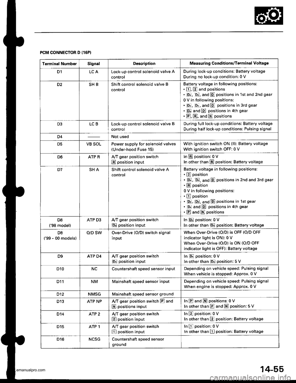
Terminal NumborSignalDescriptionMeasuring Conditions/Terminal Voltage
D1LCALock-up control solenoid valve A
control
During lock-up conditions: Baftery voltage
During no lock-up condition: 0 V
D2SHBShift control solenoid valve B
control
Battery voltage in following positions:
. E, E and positions
. E, -ql, and E positions in lst and 2nd gear
0 V in following positions:
. E, E;, and E positions in 3rd gear
. E and E positions in 4th gear
. E, El, and El positions
D3LCBLock-up control solenoid valve B
control
During full lock-up conditions: Battery voltage
During half lock-up conditions; Pulsing signal
D4Not used
D5VB SOLPower supply for solenoid valves
(Under-hood Fuse 15)
With ignition switch ON (ll); Battery voltage
With ignition switch OFF: 0 V
D6ATP RAy'T gear position switch
B position input
In E position: OV
In other than E position: Baftery voltage
D7SHAShift control solenoid valve A
control
Battery voltage in following positions:
. E position
. E, E, and E positions in 2nd and 3rd gear
. E position
0 V in following positions:
. E position. E. E, and E positions in lst gear
. Erl and E positions in 4th gear
.EandEpositions
D8
{'98 model}
ATP D3Ay'T gear position switch
E position input
In E position: 0V
In other than E position: Baftery voltage
D8
('99 - 00 models)
O/D SWOver-Drive (O/D) switch signal
input
When Over-Drive {O/D) is OFF (O/D OFF
indicator light is ON): 0 V
When Over-Drive {O/D) is ON {O/D OFF
indicator light is oFF): Battery voltage
D9ATP D4A/f gear position switch
E position input
In E position: 0V
In other than E position: 5 V
D10NCCountershaft sDeed sensor inoutDepending on vehicle speed: Pulsing signal
when vehicle is stopped: Approx.0 V
Dl1NMMainshaft speed sensor inputDepending on vehicle speed: Pulsing signal
When engine is stopped: Approx. 0 V
D12NMSGMainshaft speed sensor ground
D13ATP NPA,/T gear position switch E and
El positions input
InEandEpositions: 0V
In other than E and m position: 5 V
D14AlP 2A/T gear position switch
El position input
InE position; 0V
In other than E position: Battery voltage
D15ATP 1A,/T gear position switch
E position input
InEposition:0V
ln other than El position: Battery voltage
D16NCSGCountershaft speed sensor
grouno
PCM CONNECTOR D (16P)
14-55
www.emanualpro.com
Page 572 of 1395
Troubleshooting Procedures
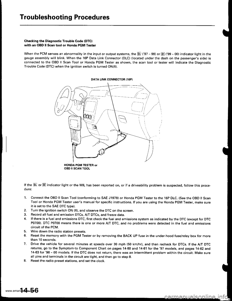
Checking ths Diagnostic Trouble Code (DTC)
with an O8D ll Scan tool or Honda PGM Tsster
When the PCM senses an abnormality in the input or output systems, the El ('97 - 98) or E ('99 - O0) indicator light in thegauge ass€mbly will blink. When the 16P Data Link Connector (DLC) {located under the dash on the passenger's side) is
connected to the OBD ll Scan Tool or Honda PGM Tester as shown, the scan tool or tester will indicate the Diagnostic
Trouble Code (DTC) when the ignition switch is turned ON(ll).
HONDA PGM TESTER olOBD II SCAN TOOL
lf the E or E indicator light or the MIL has been reported on, or if a driveability problem is suspected, follow this proce-
dure:
1. Connect the OBD ll Scan Tool (conforming to SAE J1978) or Honda PGM Tester to the 16P DLC. (See the OBD ll ScanTool or Honda PGM Tester user's manual for specific instructions. lf you are using the Honda PGM Tester, make sureit is set to the SAE DTC Wpe).2. Turn the ignition switch ON (ll), and observe the DTC on the screen
3. Record allfuel and emission DTCS, A,,/T DTCS, and freeze data.
4. lf there is a fuel and emissions DTC, first check the fuel and emissions system as indicated by the DTC (except for DTCP0700). DTC P0700 means there is one or more Ay'T DTC, and no Droblems were detected in the fuel and emissionscircuit of the PCM.
5. Wire down the radio station presets.
6. Reset the memory with the PGM Tester o. by removing the BACK UP fuse in the under-hood fuse/relay box for morethan 10 seconds.
7. Drive the vehicle for several minutes at speeds over 30 mph (50 km/hr), and then recheck for DTCS. lf the A/T DTCreturns, 9o to the Symptom-to Component Chart on pages 14-60 and 14-61 for the '97 models, and pages 14-62 and14-63 for '98 - 00 models. lf the OTC does not return, there was an intermittent problem within the circuit. Make sureall pins and terminals in the circuit are tight, and then go to step 8.8. Reset the radio Dreset stations, and set the clock.
DATA LINK CONNECTOR {16PI
[ -=.r,
ili,i /i,
v,., i
14-56
www.emanualpro.com
Page 575 of 1395
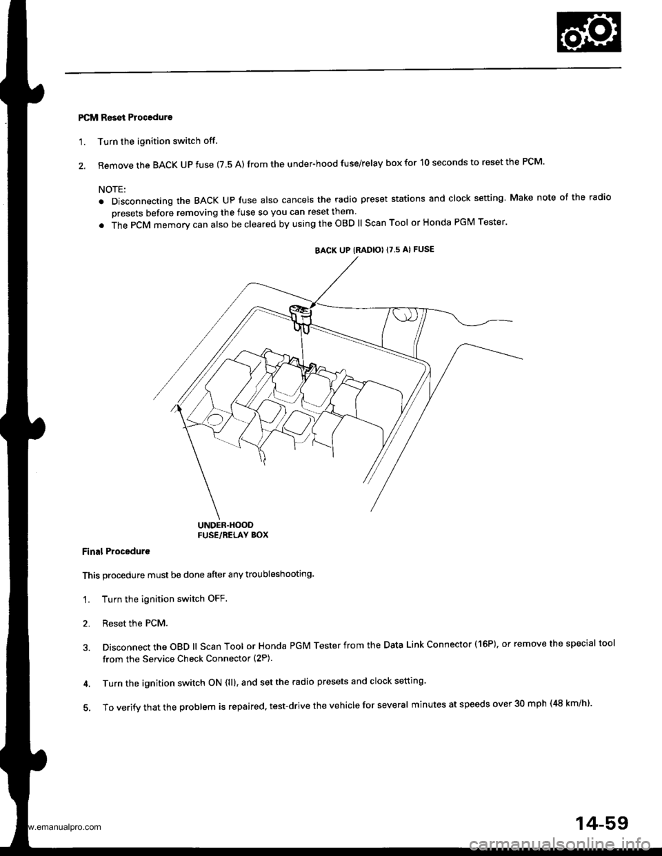
PCM Reset Procedure
'1. Turn the ignition switch off
2. Remove the BACK UP fuse (7.5 A) from the under-hood fuse/relay box for 10 seconds to reset the PCM.
NOTE:
. Disconnecting the BACK Up fuse also cancels the radio preset stations and clock setting Make note of the radio
presets before removing the fuse so you can reset them
. The PCM memorv can also be cleared by using the OBD ll Scan Tool or Honda PGM Tester'
UNDER.HOODFUSE/RELAY BOX
Final Proceduro
This procedure must be done after any troubleshooting.
1. Turn the ignition switch OFF.
2. Reset the PCM.
3. Disconnect the OBD ll Scan Tool or Honda PGM Tester from the Data Link Connector (16P), or remove the special tool
from the Service Check Connector (2P).
4. Turn the ignition switch ON (ll), and set the radio presets and clock setting'
5, To verify that the problem is repaired. test-drive the vehicle for several minutes at speeds over 30 mph (48 km/h).
BACK UP IRADIO} {7.5 AI FUSE
14-59
www.emanualpro.com
Page 579 of 1395
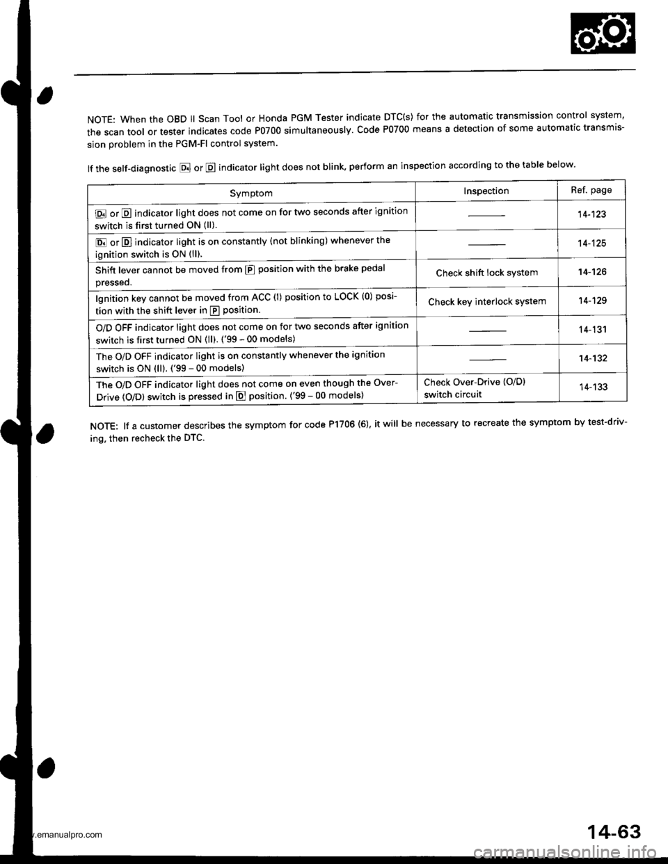
NOTE: When the OBD ll Scan Tool or Honda PGM Tester indicate DTC(S) for the automatic transmission control system,
the scan tool or tester indicates code P0700 simultaneously. Code P0700 means a detection of some automatic transmis-
sion problem in the PGM-Fl control system.
lf the self-diagnostic E or E indicator light does not blink, perform an inspection according to the table below.
NOTE: lf a customer describes the symptom for code P17OO (6), it will be necessary to recreate the symptom by test-driv-
ing. then recheck the DTC.
SymptomInspectionRef. page
E or E indicator light does not come on for two seconds after ignition
switch is first turned ON (ll).14-123
E or E] indicator light is on constantly (not blinking) whenever the
ignition switch is oN {ll).
14-125
Shift lever cannot be moved from E position with the brake pedal
presseo.Check shift lock system14-'t26
lgnition key cannot be moved from ACC (l) position to LOCK (0) posi-
tion with the shift lever in E position.Check key interlock system14-129
O/D OFF indicator light does not come on for two seconds after ignition
switch is first turned ON (ll). ('99 - 00 models)14-131
The O/D OFF indicator light is on constantly whenever the ignition
switch is ON (ll). ('99 - 00 models)14-132
The O/D OFF indicator light does not come on even though the Over-
Drive (O/Dl switch is pressed in E position. ('99 - 00 models)
Check Over-Drive {O/D}
switch circuit14-133
14-63
www.emanualpro.com
Page 592 of 1395

Electrical Troubleshooting ('97 Model)
Troubleshooting Flowchart - Countershaft Speed Sensor
Possible Cause
. Loose or faulty connection betweenih€ PCM and vehicle harness. Disconnected countershaft spoedsensor conneclor. Short or open in countershaft speed
. Faulty counteBhaft speed lensor
lf the Honda PGMTester is available:I
J
COUNTERSHAFT SPEED SENSOR
CONNECTOR
ll-'T,ll-rT
ral
YIL__l
Terminal side of male terminals
. OBO ll Scan Tool indicates Codem720.' solt-diagnosis iD!' indicator lightblink3 nine tim6s.
Check and record the freeze datain case it is needed later for problem verification.
Connect the Honda PGM Tester,and test-drive the vehicle withthe tester in Data Link or snap'Shot mode, Make sure the coun-tershaft speed sensor reads thesame as the vehicle speed sensorlVSS).
The countershaft sooed sensor isOK sr this time. Veritv that allconnecloas in the circuit aremaking good contacl.
Check the countershaft speedsensor installation, and check itfor damage.
ls the countershaft speed sen-sor installed properly, and notdamaged?neinstall or roDlaco and recheck.
Measuro CountoBhaft Speed Sen-sor Relbtance at the Sensor Con-nector:1. Disconnect the 2P connectorfrom the countershaft speedsensor connector.2. Measure the resistance of thecountershaft speed sensor.
ls the resistance 400 - 600 o?
To page 14-77
14-76
www.emanualpro.com
Page 599 of 1395
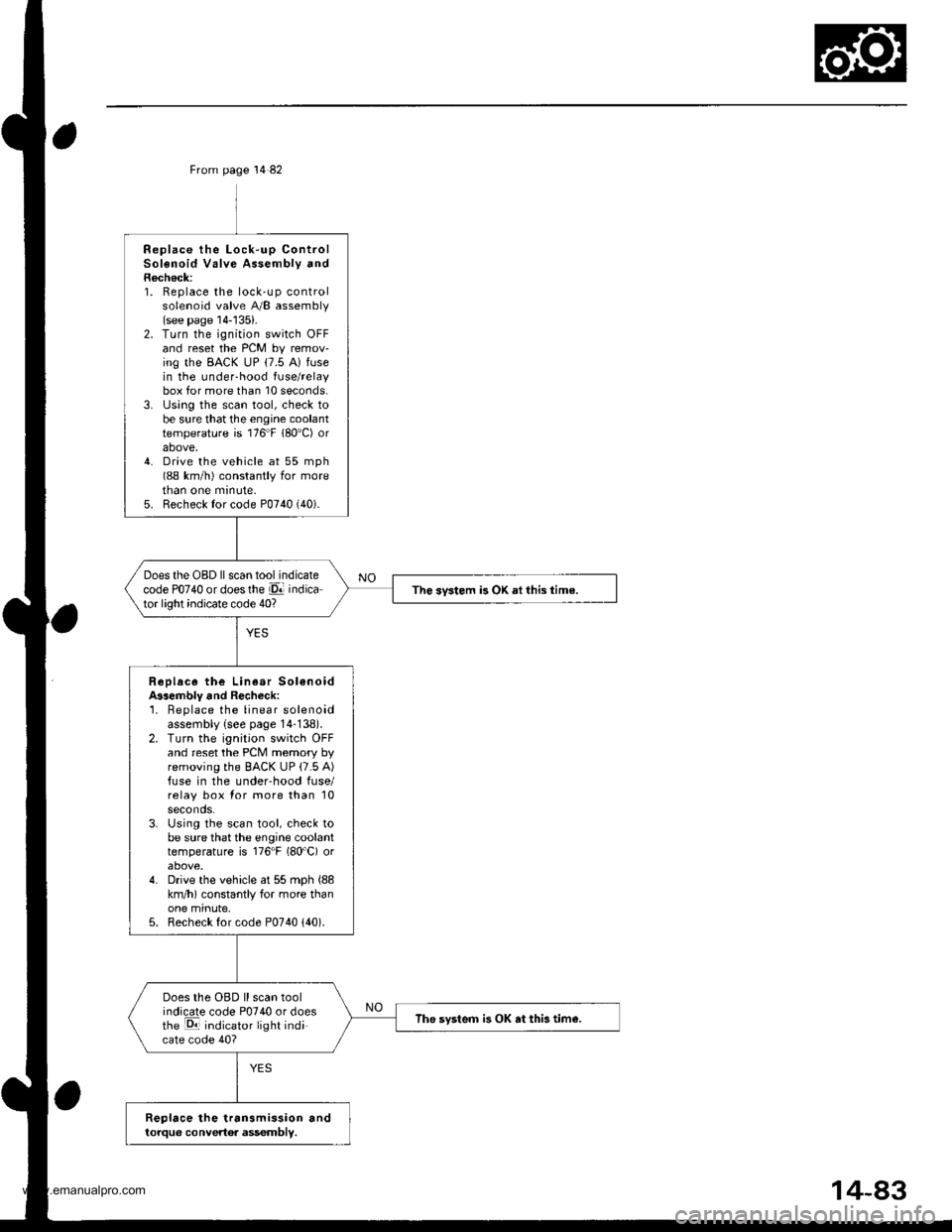
From page 14 82
Replace the Lock-up ControlSolenoid Valve Assembly andRecheck:1. Replace the lock-up controlsolenoid valve A/B assembly(see page 14-'135).2. Turn the ignition switch OFFand reset the PCM by remov-ing the BACK uP (7.5 A) fusein the under-hood fuse/relaybox for more than 10 seconds.3. lJsing the scan tool, check tobe sure that the engine coolanttemperature is 176"F 180'C) orabove,4. Drive the vehicle at 55 mph(88 km/h) constantly for moretnan one mrnute.5. Recheck for code P0740 (40).
Does the OBD ll scan tool indicatecode PO74O or doesthe El indicator light indicate code 40?The svstem is OK ai this time.
Replace the Linear Sol€noidA$embly and Recheck:'1. Beplace the linear solenoidassembly {see page 14-138).2. Turn the ignition switch OFFand reset the PCM memory byremoving the BACK UP (7.5 A)fuse in the underhood fuse/relay box for more than 10seconds.3. Using the scan tool, check tobe sure that the engine coolanttemperature is 176"F (80'C) orabove.4. Drive the vehicle at 55 mph (88
km/h) constantly for more thanone minute,5. Recheck for code P0740 {40).
Does the OBD ll scan toolindicate code P0740 or doesthe E indicator light indicate code 40?
The svsteo is OK at this tim€.
Replace the transmission andtorque convertor assembly.
www.emanualpro.com