1999 HONDA CR-V engine no start
[x] Cancel search: engine no startPage 23 of 1395
Towing
lf the vehicle needs to be towed, call a professional
towing service. Never tow the vehicle behind another
vehjcle with just a rope or chain. lt is very dangerous.
Emergency Towing
There are three popular methods of towing a vehicle.
Flat-bed Equipment - The operator loads the vehicle on
the back of a truck. This is the best way of transporting the
vehicle.
Wheel Lift Equipment - The tow truck uses tlvo pivoting
arms that go under the tires lfront or rear) and lifts them
off the ground. The other two tires remain on the
ground. The vehicle's suspension and body can be
seriously damaged if this method of towing is attempted.
Sling-type Equipment - The tow truck uses metal cables
with hooks on the ends. These hooks go around parts of
the frame or suspension and the cables lift that end of
the vehicle off the ground. The vehicle's suspension and
body can be seriously damaged if thjs method of towing
is attempted. This methed of towing the CR-V is
unaccePtable.
The onlv recommended way of towing the CR-V is on a
flat-bed truck. Two wheel drive CR-V's may also be
towed with all four wheels on the ground.
Towing the four-wheel dlive CR-v with only two
wheels on the ground will damage parts of the 4wD
system. It this vehicle is damaged, it should be towed
on a flat-bed truck ol trailel.
It the 2 wheel drive CR-v is towed wiih all tour wheels
on the ground, do the following:
Manual Transmission
. Release the parking brake.
. Shift the transmission in Neutral
Automatic Transmission
. Release the parking brake.
. Sta rt the engine.
. Shift to lD.l position. then E position.
. Turn off the engine.
lmproper towing preparation will damage the
transmission. Follow the above procedure exactly. lf
you cannot shift the transmission or start the engine,
the vehicle must be transported on a flat-bed truck.
lf the vchicle is towed with four wheels on the ground,
il is best to tow the vehicle no larther than 50 miles (80
km), and keep the speed below 35 mph {55 km/h).
Trying to lift or tow the vehicle by ihe bumpers will
cause serious damage. The bumpers ale not dosigned
to support the vehicle's weight.
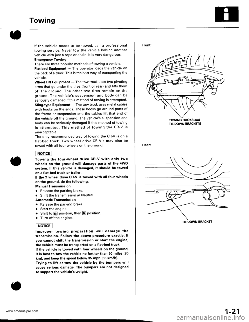
Front:
Rear:
lOwlNG HOOKS .ndTIE DOWN BRACKETS
TIE DOWN BRACKET
1-21
www.emanualpro.com
Page 29 of 1395
Standards andService Limits
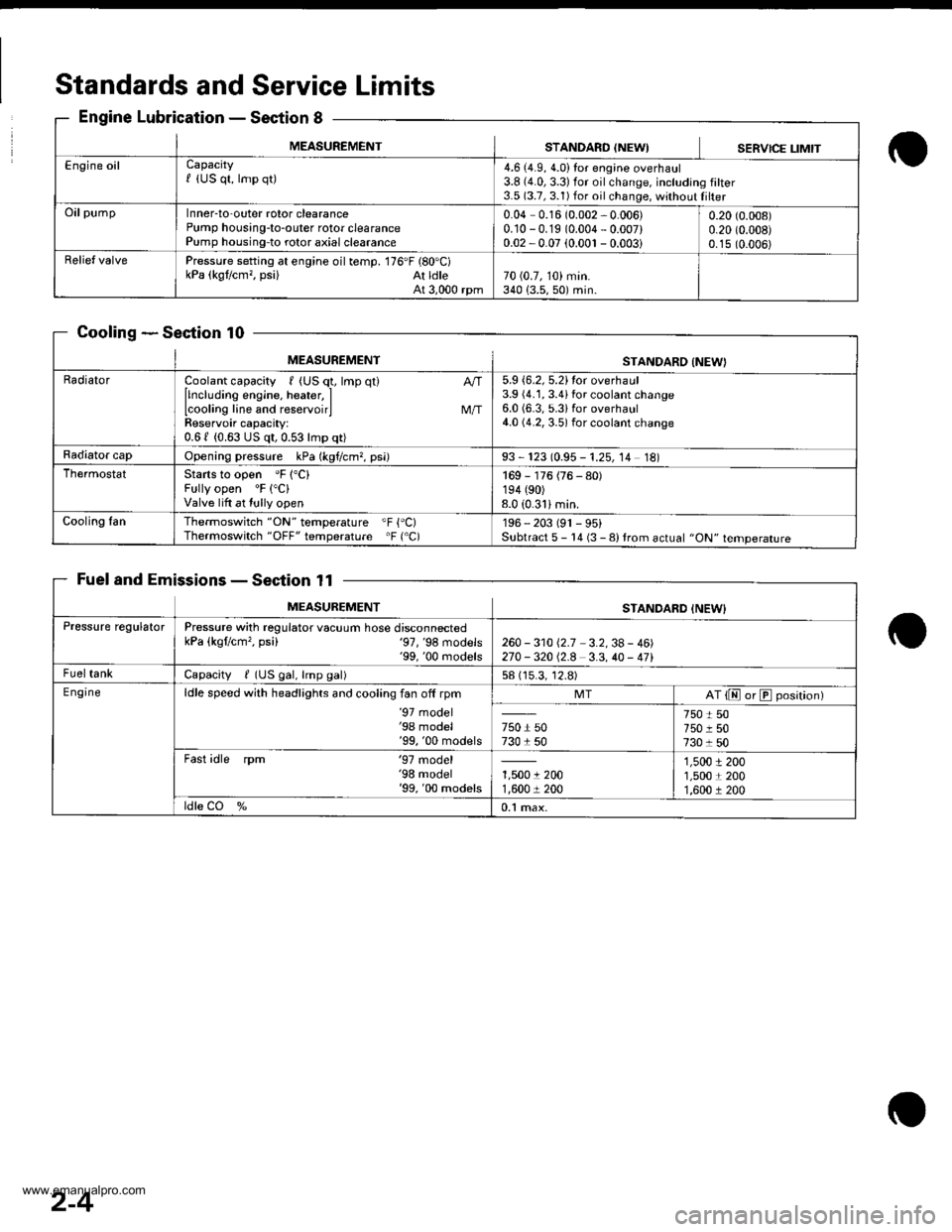
Engine LubricationSection 8
CoolingSection 10
Fuel and EmissionsSection 11
MEASUREMENTSTANDARO {NEWISERVICE LIMIT
Engine oilCapacityf (US qt, lmp qt)4.6 (4.9, 4.0)Ior engine overhaul3.8 {4.0,3.3)for oilchange, including filter3.5 (3.7, 3.1) for oil change, without Iilter
OilpumpInner-to-outer rotor clearancePump housing-to-outer rotor clearancePump housing-to rotor axial clearance
0.04 - 0.16 (0.002 - 0.006)0.10 -0.19 (0.004 - 0.007)0.02 -0.07 (0.001 - 0.003i
0.20 (0.008)
0.20 (0.008)
0.15 (0.006)
Relief valvePressure setting at engine oil temp. 176'F (80'C)kPa (kgt/cm,, psi) At ldleAt 3,000 rpm70 (0.7, 10) min.340 {3.5,50) min.
MEASUREMENTSTANDARO INEW}
RadiatorCoolant capacity , (US q1, lmp qt)
llncluding engine, heater, ILcooling line and reservoirlReservoir capacity:0.61 (0.63 US qt,0.53lmp qt)
M/T
5.9 {6.2, 5.2}tor overhaul3.9 (4.1, 3.4ifor coolant change6.0 (6.3, 5.3ifor overhaul4.0 (4.2, 3.5) for coolant change
Radiator capOpening pressure kPa (kgf/cm?, psi)93 - 123 (0.95 - 1.25, 14 18)
ThermostatStarts to open 'F 1"C)Fully open 'F ("C)
Valve lift at tully open
169 - 176 (76 - 80)194 (90)
8.0 (0.31imin.
Cooling fanThermoswitch "ON" temperature "F {'C)Thermoswitch "OFF" temperature 'F ('C)196 - 203 (91 - 95)Subtract 5 - 14 (3 - 8) trom actual "ON" temperature
MEASUREMENTSTANDARD INEW}
Pressure regulatorPressure with regulator vacuum hose disconnectedkPa (kgflcm'�, psi) '97,'98 models'99, '00 rnodels260 - 31012.7 3.2,38- 46)270 -32012.8 3.3,40 - 471
FueltankCapacity / (US gal, lmp gal)58 (15.3, 12.8)
E ngineldle speed with headlights and cooling fan off rpm'97 model'98 model'99, '00 models
MTAT {E or E position)
750 r 50730 1 50
750 t 50750 r 507301 50
Fast idle rpm '97 model'98 model'99, '00 models1,5001 2001,600 r 200
1,5001 2001,5001 2001,600 r 200
ldle CO %0.1 max.
2-4
www.emanualpro.com
Page 37 of 1395
Design Specifications
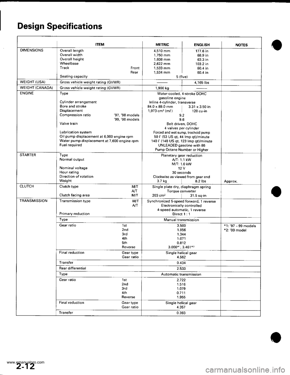
ITEMMETRICENGLISHNOTES
DIMENSIONSOverall lengthOverallwidthOverall heightWheelbaseTrack FrontRearSeating capacity
4,510 mm1,750 mm1,608 mm2,622 mrn1,533 mm1,534 mm5lf
177.6 in68.9 in63.3 in103.2 in60.4 in60.4 in
WEIGHT (USA)Gross vehicle weight rating (GVWR)| 4,165 tbs
WEIGHT (CANADA)Gross vehicle weight rating (GVWR)1,900 kg
ENGINEType
Cylinder arrangementBore and strokeDisplacementCompression ratio '97,'98 mooers'99, '00 modelsValve train
Lubrication systemOil pump displacement at 6,000 engine rpmWater pump displacement at 7,600 engine rpmFuel required
Water-cooled, 4-stroke DOHCgasoline engineInline 4-cylinder, transverse84.0 x 89.0 mm.1,973 cm3 (m{)
9.2
3.31 x 3.50 in120 cu-in
9.6Belt driven, DOHC4 valves per cylinderForced and wet sump, trochoid pump501 (53 US qt,44 lmp qt)/minute1401 (148 US qt, 123 lmp qt)/minuteUNLEADED gasoljne with 86Pump Octane Number or Higher
STARTERTypeNormal output
NominalvohageHour ratingDirection of rotationWeight
Planetary gear reductionA/T: 1.1 kWM/T: 1.0 kW12V30 secondsClockwise as viewed from gear end3.7 kg 8.2 lbsApprox.
CLUTCHClutch type
Clutch lacing area
MIT
MIT
Single plate dry, diaphragm springTorque converter203 cm, 31.5 sq-in
TRANSMISSIONTransmission type
Primary redLrction
MITSynchronized s-speed torward, 1 reverseElectronically controlled4-speed automatic, 1 reverseDirect I : 1
TypeManualtransmission
Gear ratio 1st2nd3rd4th5thReverse
3.5001.9561.3441.0710.8123.000*,. 3.461*'
*1: '97 - 99 models*2: '00 model
Final reduction Gear typeGear rataoSingle helical gear4.562
Transfer0.434
Rear differential2.533
TypeAutomatic transmission
Gear ratio 1st2nd3rd4thReverse
2.722
1.0790.7111.955
Final reduction Gear typeGear ratioSingle helical gear4.357
Transfer0.393
2-12
www.emanualpro.com
Page 51 of 1395
Engine Electrical
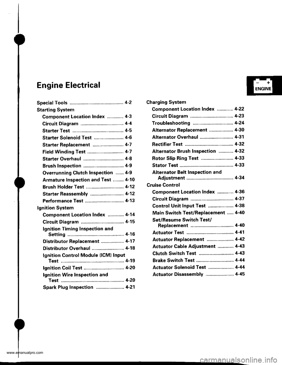
Speciaf Tools ............. 4-2
Starting System
Component Location Index ............ 4-3
Circuit Diagram ................................ 4-4
Starter Test ........... 4-5
Starter Solenoid Test ...................... 4'5
Starter Replacement ....................... 4-7
Field Winding Test ........................... 4-7
Starter Overhaul ............................,. 4-8
Brush Inspection ...........................,., 4-9
Overrunning Glutch Inspection ...... 4-9
Armature lnspection and Test ........4-10
Brush Holder Test ............................ 4-12
Starter Reassemb|y ......................... 4-1 2
Perf ormance Test ............................. 4- 1 3
lgnition System
Component Location Index ............ 4-14
Circuit Diagram ................................ 4-15
lgnition Timing Inspection and
Setting .......................................... 4-16
Distributor Replacement ........,........ 4-17
Distributor Overhaul .............,,......... 4-18
lgnition Control Module (lCM) Input
Test ..............................,................ 4-19
fgnition Coil Test .............................. 4-2O
lgnition Wire Inspection and
Test ............................................... 4-20
Spark Plug Inspection ..................... 4-21
-+
ENGINE
Charging System
Component Location Index ............ 4-22
Circuit Diagram ....................,........... 4-23
Troubleshooting .............................. 4-24
Alternator Replacement ..........,....... 4-30
Alternator Overhaul .......,,................ 4-31
Rectifier Test .........4-32
Alternator Brush Inspection ........... 4-32
Rotor Slip Ring Test ........................ 4-33
Stator Test ............. 4-33
Alternator Belt Inspection and
Adiustment ........4-34
Gruise Control
Component Location Index .,,,........ 4-36
Circuit Diagram ................................ 4-37
Control Unit Input Test ................... 4-38
Main Switch Test/Replacement ..... 4-40
Set/Resume Switch Test/
Replacement .......................,........ 4'40
Actuator Test ....,,., 4-41
Actuator Replacement ...............,.... 4-42
Actuator Cable Adiustment ............ 4-43
Clutch Switch Test .......................... 4-43
Brake Switch Test .................. .......... 4-44
Actuator Solenoid Test .............. ...,. 4-44
Actuator Disassembly ..................... 4-45
www.emanualpro.com
Page 55 of 1395

Starting System
Starter Test
NOTE: The air temperature must be between 59 and'100'F (15 and 38"C) before testing.
Recommended Procedure:
. Use a staner system tester.
. Connect and operate the equipment in accordance
with the manufacturer's instructions.
. Test and troubleshoot as described.
Alte.nate Procedure:
. Use the following equipment:- Ammeter, 0 - 400 A- Voltmeter, 0 - 20 V (accurate within 0.1 volt)
Tachometer,0 - 1,200 rpm
. Hook up a voltmeter and ammeter as shown.
NOTE: After this test, or any subsequent repair. reset
the ECM/PCM to clear any codes (see section 1 1).
Check the Starter Engagement:
'1. Remove the No. 44 (15 A) fuse from the under-hood
fuse/relay box.
2. Turn the ignition switch to START (lll) with the shift
lever in E or E position (A/T) or with the clutch
pedal depressed {M/T). The starter should crank the
eng ine.
. lf the starter does not crank the engine, go to
step 3.
. lf it cranks the engine erratically or too slowly, go
to "Check for Wear and Damage" on the next
page.
NEGATIVE TERMINAL
4.
5.
6.
7.
8.
Check the battery, battery positive cable, ground.
staner cut relay, and the wire connections for loose-
ness and corrosion. Test again.
lf the staner still does not crank the engine, go to
step 4.
Unplug the connector (BLK /VHT wire and solenoid
terminal) from the starter.
Connect a jumper wire from the baftery positive (+)
terminal to the solenoid terminal.
The starter should crank the engine.
. lf the starter still does not crank the engine,
remove it, and diagnose its internal problem.
. lf the starter cranks the engine, go to step 6.
Check the ignition switch (see section 23).
Check the starter cut relay {see section 23}.
Check the IVT gear position switch (A/T) or the clutch
interlock switch (M[).
Check for an open in the wire between the ignition
switch and starter.
(cont'd)
4-5
www.emanualpro.com
Page 56 of 1395
Starting System
Starter Test (cont'dl
Check lor Wear and D8mage
The starter should crank the engine smoothly and
steadily. lf the staner engages, but cranks the engine
erratically, remove it, and inspect the starter drive gear
and torque converter ring gear or flywheel ring gear for
oamage.
Check the drive gear overrunning clutch for binding or
slipping when the armature is rotated with the drive
gear held. lf damaged, replace the gears.
Check Cranking Voltage and Current Draw
Cranking voltage should be no less than 8.7 volts on Ay'T
models, and 8.0 volts on M/T moders.
Current draw should be no more than 230 amperes on
A,/T models, and 200 amperes on M/T models.
lf cranking voltage is too low, or current draw too high,
check for:
. dead or low battery.
a open circuit in starter armature commutator seg,
ments.
. starter armature dragging.
. shorted armature winding.
. excessive drag in engine.
Check Cranking rpm
Engine speed during cranking should be above 100 rpm.
lf speed is too low, check for:
a loose baftery or starter terminals.
. excesslvely worn staner brushes
. open circuit in commutator segments.
. dirty or damaged helical splines or drive gear.
a defective drive gear overrunning clutch.
Check Starter Disengagement
With the shift lever in @ or @ position (A,iT) or with the
clutch pedal depressed {M/T). turn the ignition switch to
START (lll). and release to ON (ll).
The starter drive gear should disengage from the torque
converter ring gear or flywheel ring gear when you
release the key.
lf the drive gear hangs up on the torque converter ring
gear or flywheel ring gear, check for
. solenoid plunger and switch malfunction.
. dirty drive gear assembly or damaged overrunning
clutch.
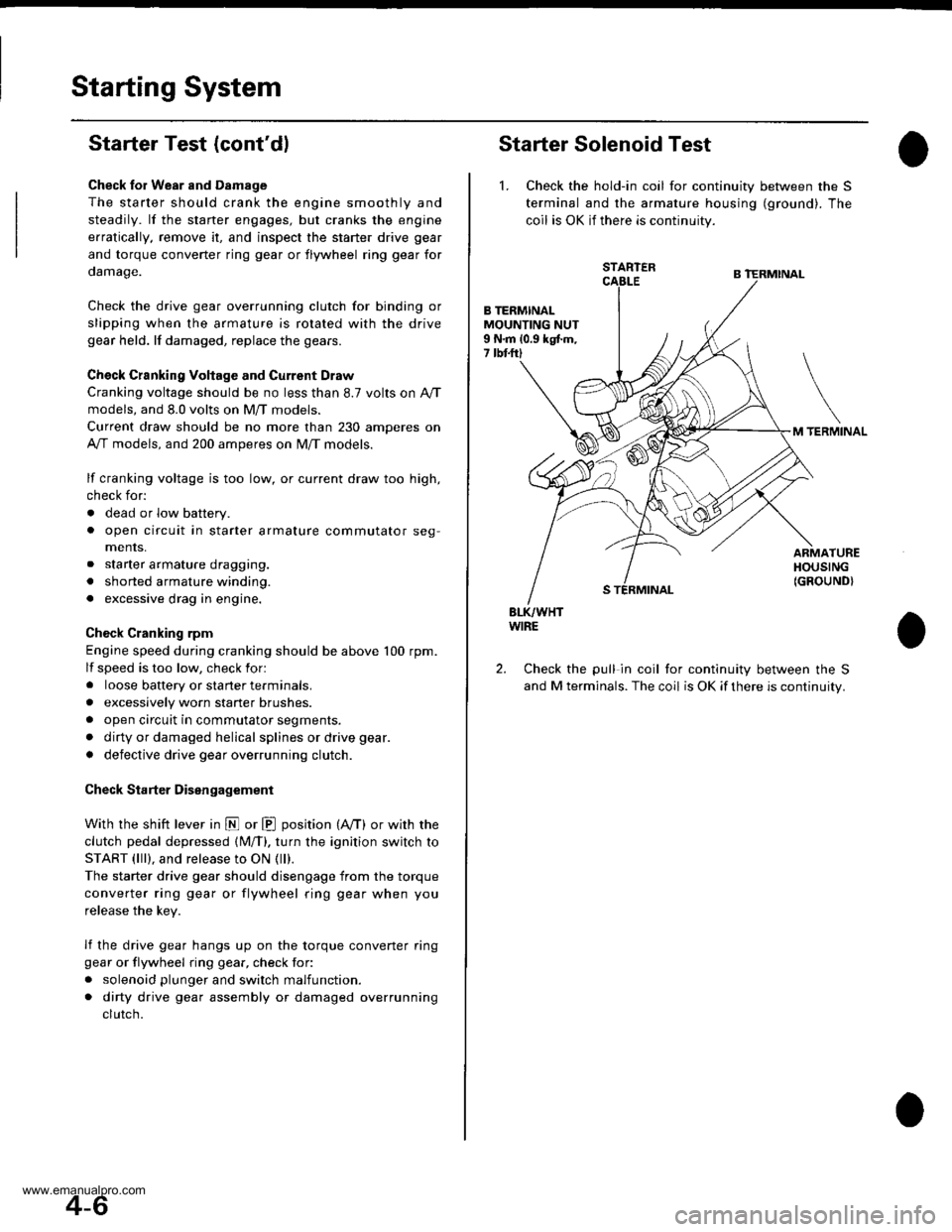
Starter Solenoid Test
1. Check the hold-in coil for continuity between the S
terminal and lhe armature housing (ground). The
coil is OK if there is continuity.
STARTER
B TERMINALMOUNTING NUT9 N.m 10.9 kgtm,7 tbtftl
TERMINAL
ARMATUREHOUSING(GROUND}
BLK/WHTWIRE
Check the pull in coil for continuity between the S
and M terminals. The coil is OK if there is continuity.
2.
4-6
www.emanualpro.com
Page 66 of 1395

lgnition System
5.
lgnition Timing Inspection and Setting
2.
1.Check the idle speed, and adjust it if necessary (see
section 1 1).
Pull out the service check connector 2P (BRN and
BLK wires) from the connector holder located under
the dash on the front passenger side, then connect
the scs service connector (P/N 07PAz - 0010100) to
it.
Start the engine. Hold the engine at 3,000 rpm with
no load (A/T in N or E, Mff in neutral) until the
radiator fan comes on, then let it idle.
Connect the timing light to the No. I ignition wire,
then point the light toward the pointer on the timing
belt cover.
Check the ignition timing in no load conditions:
headlights, blower fan, rear window defogger, and
air conditioner are not operating.
lgnition Timing:
M/T: 16" 12" BTDC (RED) idling in neutral
AlTt'16" !2" BTDC (RED) idling in E or E
CRANKSHAFTPULLEY
4-16
6. lf necessary, adjust the ignition timing as follows.
Loosen the distributor mounting bolts, and turn the
distributor ignition (Dl) housing counterclockwise to
advance the timing or clockwise to retard the tim-
t no,
7.
8.
MOUNTING BOLTS24 N.m {2.4 kgf m, 17 lbtft}
Tighten the distributor mounting bolts, and recheck
the ignition timing.
Disconnect the SCS service connector from the ser-
vice check connector.
To RETARD
www.emanualpro.com
Page 74 of 1395
Gharging System
Troubleshooting
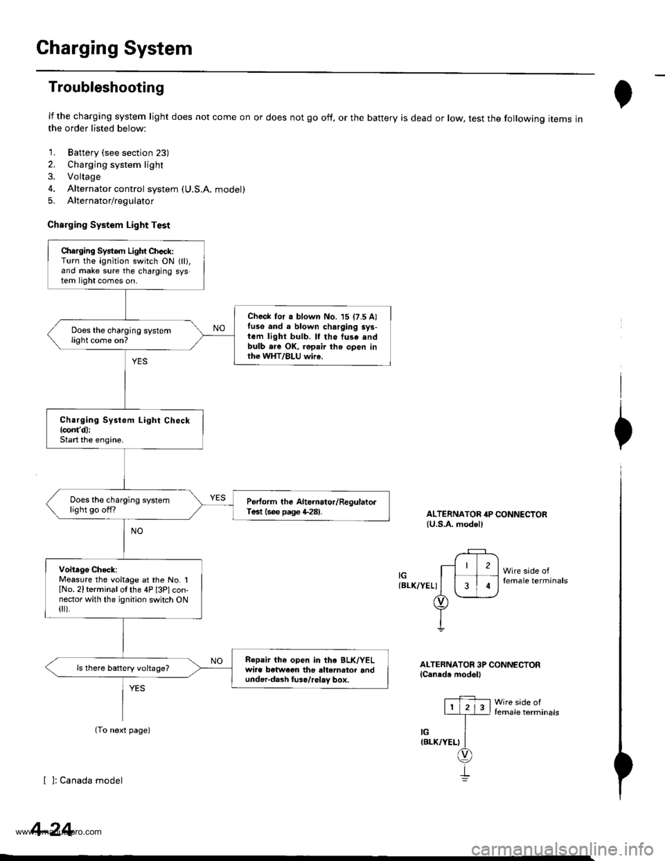
lf the charging system light does not come on or does not go off, or the battery is dead or low, test the following items inthe order listed below:
1. Battery (see section 23)
2. Charging system light
3. Voltage
4. Alternator control system (U.S.A. model)
5. Alternator/regulator
Charging System Light Test
ALTERNATOR 4P CONNECTOR{U.S,A. modell
(BLK/YEL)
2
3
Wire sade offemale terminals
I
I
I
ALTERNATOR 3P CONNECTORlCaneda model'
Iemale terminals
[ ]: Canada model
Chsrging Systom Light Check:Turn the ignition switch ON {ll),and make sure the charging system light comes on.
Check for a blown No. 15 17.5 Alfuse and a blown charging sys-tem light bulb. lf the tusa .ndbulb are OK, repair th€ open inth€ WHT/BLU wire.
Does the charging systemlight come on?
Charging System Light Check{com'd}:Start the engine.
Does the charging systemlight go offfPerform the Alte.nator/RegulatorTest lsee page +281.
Voltage Check:Measure the voltage at the No. IlNo. 2iterminal of the 4P [3Plcon-nector with the ignition switch ON{ ).
Ropair the open in the BLK/YELwiae betwoen the altemator andunder-da3h luso/relay box.
ls there battery voltage?
(To next page)
4-24
www.emanualpro.com