Page 526 of 1395
Description
Power Flow lcont'd)
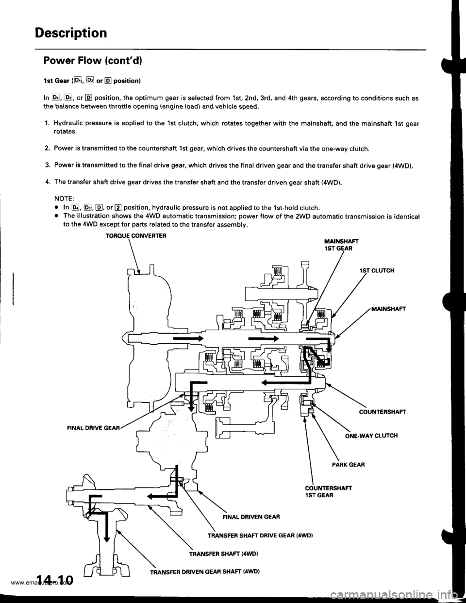
lst Gear (8. E or E positionl
In E, E, or D position, the optimum gear is selected from 1st, 2nd, 3rd, and 4th gears, according to conditions such as
the balance between throttle opening (engine load) and vehicle speed.
1. Hydraulic pressure is applied to the 1st clutch, which rotates together with the mainshaft, and the mainshaft 1st gear
rotates.
2. Power is transmitted to the countershaft 1st gear. which drives the countershaft via the one-way clutch.
3. Power is transm itted to the final drive gear.which drives the final driven gear and the transfer shaft drive gea r (4WD).
4. The transfer shaft drive gear drives the transfer shaft and the transfer driven gear shaft (4WD).
NOTE:
o In @, @, @, or E position. hydraulic pressure is not applied to the 1st-hold clutch.. The illustration shows the 4WD automatic transmission; power flow of the 2WD automatic transmission is identicalto the 4WD except for parts related to the transfer assembly.
CONVERTERMAIiISHAFT1ST
CLUTCH
MAINSHAFT
COUNTERSHAFT
FINAL OBIVE GEAR
ONE.WAY CLUTCH
PARK GEAR
FINAL DRIVEN GEAR
14-10
TRANSFER SHAFT DRIVE GEAR {4WD}
www.emanualpro.com
Page 527 of 1395
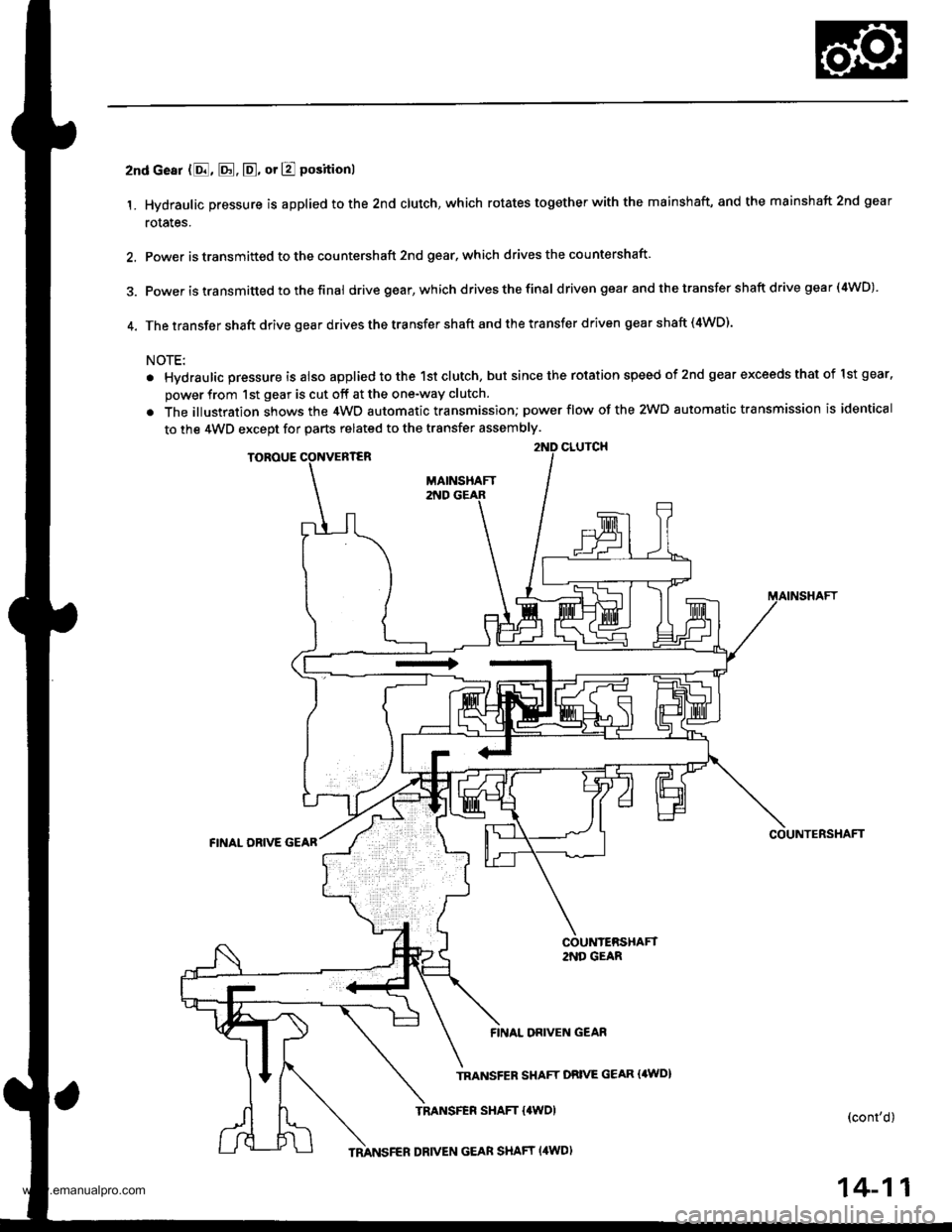
2nd cesr (8, E. E, or E positionl
1. Hydraulic pressure is applied to the 2nd clutch, which rotates together with the mainshaft, and the mainshaft 2nd gear
rotales.
2. Power is transmitted to the countershaft 2nd gear, which drives the countershaft
3. power is transmitted to the final drive gear, which drivesthefinal d riven gear and the transfer shaft drive gea r (4WD)
4. The transfer shaft drive gear drives the transfer shaft and the transfer driven gear shaft (4WD).
NOTE:
. Hvdraulic pressure is also applied to the 1st clutch, but since the rotation speed of 2nd gear exceeds that of lst gear.
power from 1st gear is cut off at the one-way clutch.
. The illustration shows the 4WD automatic transmission; power flow of the 2WD automatic transmission is identical
to the 4WD except for parts related to the transfer assembly.
CLUICHTOROUE
COUNTERSHAFTFINAL ORIVE GEAR
2NO GEAR
FINAL DRIVEN GEAF
TRANSFER SHAFT DBIVE GEAR {4WD}
TRANSFER SHAFT {4WDI(cont'd)
TMNSFER DRIVEN GEAR SHAFT (4WD)
14-11
www.emanualpro.com
Page 528 of 1395
Description
Power Flow (cont'd)
3rd Gear {8. @, or @ position)
1. Hydraulic pressure is applied to the 3rd clutch. Power from the mainshaft 3rd gear is transmitted to the countershaft
3rd gear.
2. Power is transm ifted to the final d rive gear, wh ich d rives the f inal driven gear and the transfer shaft drive gear (4WD).
3, The transfer shaft drive gear drives the transter shaft and the transfer driven gear shaft (4WD).
NOTE:
. Hydraulic pressure is also applied to the 1st clutch, but since the rotation speed of 3rd gear exceeds that of 1st gear,
power from lst gear is cut off at the one-way clutch.
. The illustration shows the 4WD automatic transmission; Dower flow of the 2WD automatic transmission is identical
to the 4WD except for parts related to the transfer assembly.
CONVERTEF
MAINSHAFT 3RD GEAR
COUNTERSHAFT
COUNTERSHAFT3RO GEAR
3RD CLUTCH
DRIVEN GEAR
SHAFT DRIVE GEAR (4WO)
TRANSFER SHAFT (,lwDl
TRANSFER ORIVEN GEAN SHAFT (4WD)
14-12
www.emanualpro.com
Page 529 of 1395

4th Goar (E or D positionl
1. Hydraulic pressure is applied to the 4th clutch, which rotates together with the mainshaft, and the mainshaft 4th gear
rotates,
2. Power is transmitted to the countershaft 4th gear, which drives the countershaft.
3. Power is transm ifted to the f inal d rive gear, which drives the fina I driven gear and the transfer shaft drive gear (4WD).
4. The transfer shaft drive gear drives the transfer shaft and the transfer driven gear shaft {4WD).
NOTE:
. Hydraulic pressure is also applied to the 1st clutch, but since the rotation speed of 4th gear exceeds that of 1st gear,
power from 1st gear is cut off at the one-way clutch,
. The illustration shows the 4WO automatic transmission; power flow of the 2WD automatic transmission is identical
to the 4WD except for parts related to the transfer assembly.
ilTH GEAR
TOROUE CONVERTER
.TH CLUTCH
COU'{TERSHAFT
REVERSE SELECTOR HUB
REVERSE SELECTOR
FINAL DRIVEN GEAR
TRANSFEB SHAFT DRIVE GEAB I'WD)
TNANSFER SHAFT I4WDI{cont'd)
14-13
TMNSFER DRIVEN GEAR SHAFT (4WDI
www.emanualpro.com
Page 530 of 1395
Description
Power Flow (cont'dl
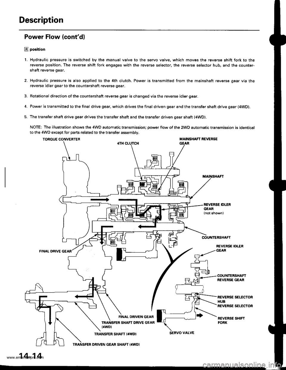
E position
1. Hydraulic pressure is switched by the manual valve to the servo valve, which movss the reverse shift fork to the
reverse position, The reverse shift fork engages with the reverse selector, the reverse selector hub, and the counter-
shaft reverse gear.
2. Hydraulic pressure is also applied to the 4th clutch. Power is transmitted from the mainshaft reverse gear via the
reverse idler gear to the countershaft reverse gear.
3. Rotational direction ofthe countershaft reverse gear ischanged viathe reverse idlergear.
4. Power is transmitted to the final drivegear,which drivesthefinal d riven gear a nd the transfer shaft drive gesr (4WD).
5. The transfer shaft drive gear drives the transfer shaft and the transfer driven gear shaft (4WD).
NOTE: The illustration shows the 4WD automatic.transmission; power flow of the 2wD automatic transmission is identical
to the 4WD except for parts related to the transfer assembly.
TOROUE CONVERTERMAINSHAFT REVERSE
COUNTERSHAFT
FINAL ORIVE
REVERSE IDLERGEAR
COUNTERSHAFTREVERSE GEAR
REVERSE SEITCTORHUBREVERSE SELECTOR
REVEBSC SHIFTFORK
FINAL OBIVEN GEAR
TRANSFER SHAFT DRIVE GEAR{4WD)
TRANSFER SHAFT {4WD)SERVO VAI-VE
14-14
TRANSFER DRIVEN GEAR SHAFT I4WD}
www.emanualpro.com
Page 532 of 1395
Description
PCM
PGM.FIControl System
Throttle Position SensorSignelVehicle Speed SensorSignal
Engin€ Coolsnt TomperatureSen30r SignalService Ch€ck Connectol
A/T Control Svstem
INTERLOCK
Shift Control
Shift ConlrolSolenoid Valve ACONTROL UNITr
RShift ControlSolenoid Valve B
N
Linear SolenoidD
Lock-up Control
2
Lock-up ControlSolenoid valve A1
Lock-up ControlSolenoid Valve BOver-DriveSwitch Signal
Mainshaft Speed SensorSignalE Indicator Light
Countershaft SpeedSensor SigntlSelt-Oiagnosis SigndSelf-DiagnosisFunc{ion
O/D OFFIndicetor Light
Electronic Gontrol System (cont'd)
'99 - 00 Models
14-16
www.emanualpro.com
Page 540 of 1395
Description
Hydraulic Control
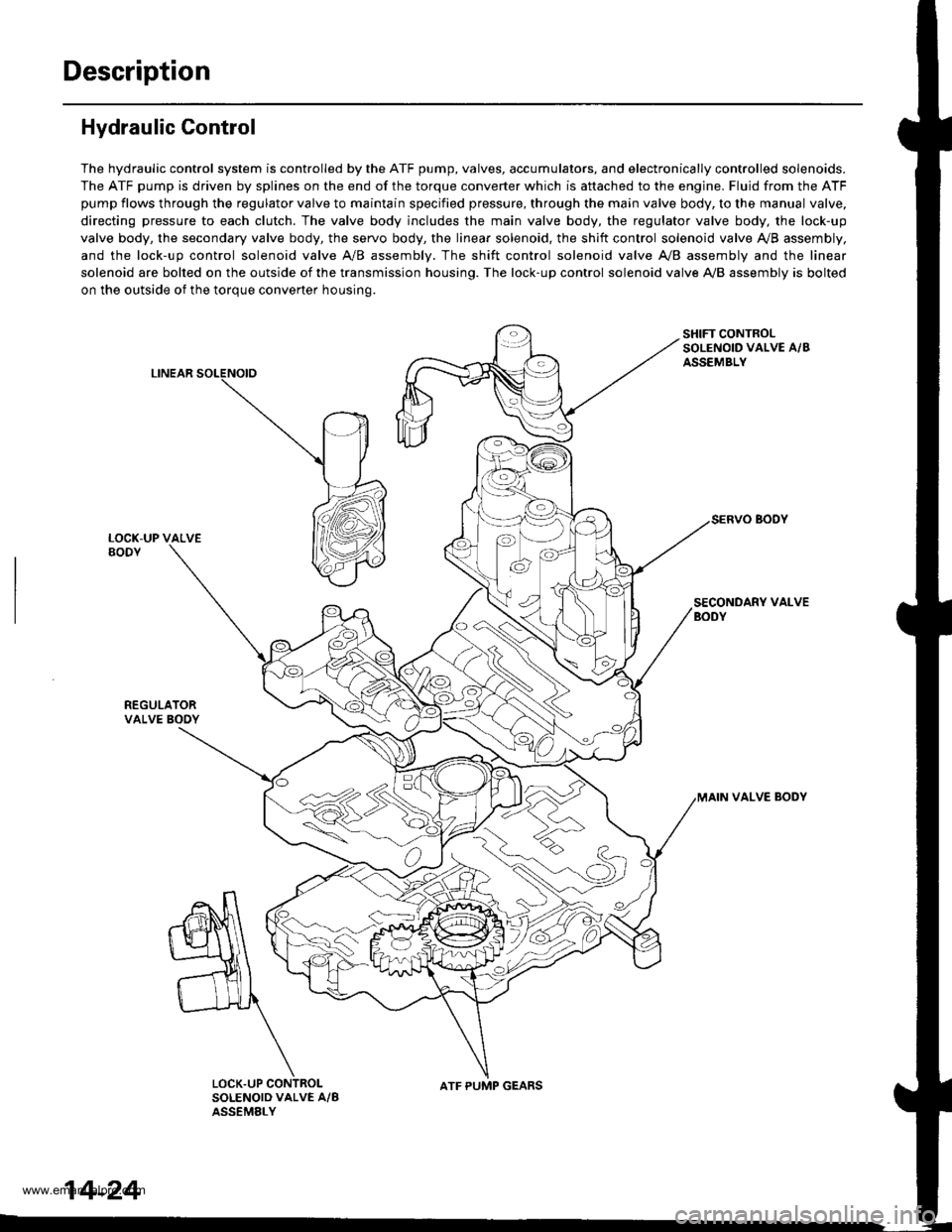
The hydraulic control system is controlled by the ATF pump, valves, accumulators, and electronically controlled solenoids.
The ATF pump is driven by splines on the end of the torque converter which is aftached to the engine. Fluid from the ATF
pump flows through the regulator valve to maintain specified pressure, through the main valve body, to the manual valve,
directing pressure to each clutch. The valve body includes the main valve body, the regulator valve body, the lock-up
valve body, the secondary valve body, the servo body, the linear solenoid, the shift control solenoid valve Ay'B assembly,
and the lock-up control solenoid valve A/B assembly. The shift control solenoid valve A,/B assembly and the linear
solenoid are bolted on the outside of the transmission housing. The lock-up control solenoid valve A,/B assembly is bolted
on the outside of the torque converter housing.
LINEAR
SHIFT CONTROLSOLENOID VALVE A/BASSEMBLY
SECONDARY VALVEBODY
REGULATORVALVE BOOY
VALVE BODY
SOLENOID VALVE A/BASSEMELY
N
ATF PUMP GEARS
14-24
www.emanualpro.com
Page 555 of 1395
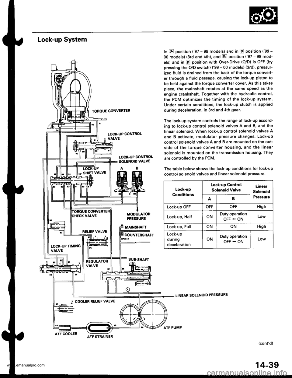
Lock-up System
TOROUE CONVERTER
In E position ('97 - 98 models) and in E position ('99 -
OO models) (3rd and 4th), and E position ('97 - 98 mod-
els) and in E position with Over-Drive (O/D) is OFF (by
pressing the O/D switch) ('99 - 00 models) (3rd), pressur-
ized fluid is drained from the back of the torque convert-
er through a fluid passage, causing the lock-up piston to
be held against the torque converter cover, As this takes
Dlace, the mainshaft rotates at the same speed as th8
engine crankshaft. Together with the hydraulic control,
the PCM optimizes the timing of the lock-up system.
Under certain condltions. the lock-up clutch is appli€d
during deceleration, in 3rd and 4th gear.
The lock-up system controls the range of lock-up sccord-
ing to lock-up control solenoid valves A and B, and ths
linear solenoid. When lock-up control solenoid valves A
and B activate. modulator pressure changes. Lock-up
control solenoid valves A and B are mounted on the out-
side of the torque converter housing, and the linear
solenoid is mounted on the transmission housing. They
are controlled bv the PCM.
The table below shows the lock-up conditions for lock-up
control solenoid valves and linear solenoid pressure.
LINEAR SOLENOID PRESSURE
(cont'd)
LOCK.UP CONTROL' VALVE
LOCK.UP CONTROLSOLENOID VALVE
AB
MODULATORPf,ESSURE
MAINSHAFT
COUNTERSHAFT
SUB.SHAFT
Lock-up
Conditions
Lock-up Conirol
Solenoid valveLinaal
Solenoid
PrgssulsAB
Lock-up OFFOFFOFFHigh
Lock-up, HalfONDuty operation
OFF - ONLow
Lock-up, FullONONHigh
Lock-up
during
deceleration
ONDuty operation
OFF - ON
RELIEF VALVE
LOCK'UP TIMINGVALVE
COOLER RELIEF VALVE
ATF COOLERATF STRAINER
ATF PUMP
14-39
www.emanualpro.com