1999 HONDA CIVIC air temp
[x] Cancel search: air tempPage 394 of 2189
IIntake Air Temperature (lATl Sensor
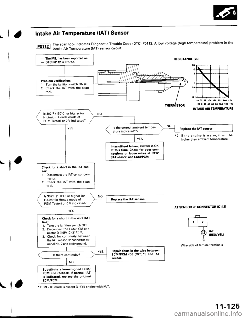
The scan tool indicates Diagnostic Trouble Code {DTC) P0112: A low voltage (high temperature) problem in the
lntake Air Temperature (lAT) sensor circuit.
RESISTANCE IKOI
.-l
*2: lf the engine is warm, it will be
higher than ambient temPerature.
IAT SENSOR 2P CONNECTOR {C112)
. a2 .. toa rra rrl l:rt t.al20 0 20 ro ao ao too t2ot.cl
INTAXIE AIR TEMPEFATURE
IAT{RED/YEL)
termrnars
-+-r
I'l'l-_T-
I=
Wire side of female
The MIL has been Teported on.
DTC P0112 is stored.
Problem verification:1. Turnthe ignition switch ON 1ll)2. Check the IAT with the scan
tool-
ls 302'F (150"C) or hagher (or
H Limit in Honda mode ot
PGM Tester) or 0 V indicated?
ls the correct ambrent temper
ature indicatedi'�?Roolac€ tho IAT 3ensor.
lntermittent failure, svstom is OK
6t this tim€. Check for Poor Gon-
nections or loos€ wires st C112
{lAT.en3orl and ECM/PCM.
Check tor a shon in the IAT sen-
sor:1. Disconnect the IAT sensor con
nector.2. Check the IAT with the scan
tool.
ls 302"F (150'C)or higher (or
H'Limit in Honda mode of
PGM Tester) or 0 V indicated?
Ch6ck for s short in the wira (lAT
lin€):1. Turn the ignition switch OFF
2. Disconnect the ECM/PCM con-
nector D (16P) (C (31P))*'.
3. Check for continuity between
the IAT sensor 2P connector ler-
minal No. 2 and body ground.
Reoair short in the wire bstweenECM/PCM tD8 (c25)'1) and IAT
Substitute a known-good ECM/
PCM and recheck. It normel IAT
is indicated, replace the original
ECM/PCM.
* l: '99 - 0O models except Dl6Y5 engine with M/T-rf,
11-125
Page 395 of 2189
PGM-FI System
Intake Air Temperature (lAT) Sensor
('96 - 98 Models,'99 - 00 D16Y5 engine with M/Tl
11-126
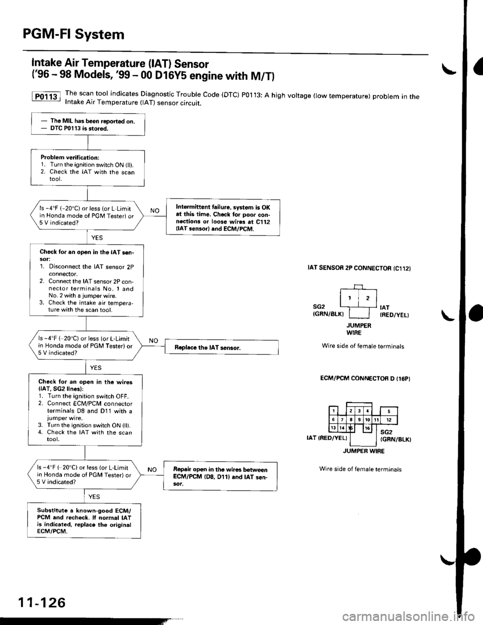
The scan tool indicates Diagnostic Trouble Code (DTC) POl13: A high voltage flow temperature) problem in theIntake Air Temperature (lAT) sensor circuit,
taT sENsoR 2P CONNECTOn (Cl12l
I' jrl
SG2 '---.]__+ tAT(GRN/BLKI I I IRED/YEL}
JUMPERWIRE
Wire side of female terminals
ECM/PCM CONNECTOR D (16PI
IAT IRED/YEL)sG2(GRN/BLK)
JUMPER WIRE
Wire side of female terminals
The MIL has been reported on.DTC P0113 b sto.6d.
Problem veritication:1. Turn the ignition switch ON (ll).2. Check the IAT with the scantool.
Intermittent tailuJe, systom is OKat this time, Check to. poor con-nections or loose wir.s at C112{lAT senso.l .nd ECM/PCM,
ls -4'F 1-20"C) or less (or L Limitin Honda mode of PGNI Tester) or5 V indicated?
Check for an open in the IAT sen-sol:1. Disconnect the IAT sensor 2pconnector,2. Connect the IAT sensor 2P con-nector terminals No, 1 andNo.2 with a jumper wjre.3. Check the intake air tempera,ture with the scan tool.
ls -4"F ( 20'C) or less (or L-Limitin Honda mode of PGM Tester) or5 V indicated?Repbce the IAT sensor.
Check tor an open in th6 wires{lAT. SGzline!):1. Turn the ignition switch OFF.2. Connect ECM/PCM connectorterminals D8 and D11 with a
3. Turn the ignition switch ON (ll).4. Check the IAT with the scantool.
ls -4"F ( 20'C) or less (or L-Limitio Honda mode ol PGM Tester) or5 V indicated?
R€p6ir opan in the wiro! hweenEC-M/PCM lD8. 011l and IAT sen-
Substitute a known-good ECM/PCM end recheck. lf normal IATis indic.ted, replace the originalECM/PCM.
Page 396 of 2189
L
I
Intake Air Temperature (lAT) Sensor
('99 - 00 Modeis except D16Y5 engine with M/Tl
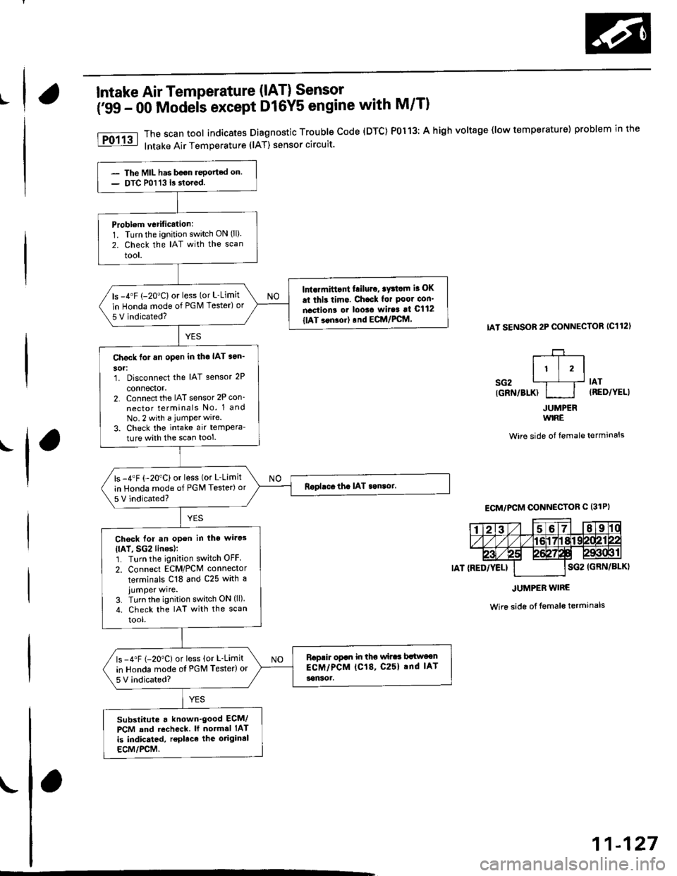
The scan tool indicates Diagnostic Trouble code (DTC) P0113: A high voltage (low temperature) problem in the
Intake Air Temperature (lAT) sensor circuit.
IAT SENSOR 2P CONNECTOB IC112'
r-+-r
It l,lsG2 L1__f lAr
IGRN/BLK} I I (RED/YELI
JUMPERWIRE
Wire side of female terminals
Wire side of lemale terminals
The MIL has be€n rePorted on.
DTC P0113 i3 stored.
Probl€m vetification:1. Turn the ignition switch ON (ll).
2. Check the IAT with the scan
tool.
Intormittont f.iluro, tyrtom i. OK
.t thi! tim.. Chocl for Poor con'
nactions or looso wit6 !t C112
tlAT ..n!or) rnd ECM/PCftl,
ls -4"F (-20"C) or less (or L-Limit
in Honda mode of PGM Tester) or
5 V indicated?
Check tor an open in tho IAT son'
304:1. Disconnect the IAT sensor 2P
connector,2. Connect the IAT sensor 2P con_
nector terminals No. 1 and
No.2 with a jumPerwire.
3. Check the intake air tempera-
ture with the scan tool.
ls -4"F {-20"C) or less (or L-Limit
in Honda mode of PGM Tester) or
5 V indicated?
Check lor an open in iho wirg3
{lAT, SG2 linesl;1. Turn the ignition switch OFF
2. Connect ECM/PCM connector
terminals C18 and C25 with a
iumper wire.3. Turn the ignition switch ON (ll)
4. check the IAT with the scan
tool.
Roprir opan in tho wilaa brlwocn
ECM/PCM (C18, C25l .nd IAT
!on30r.
ls -4"F (-20"C) or less (or L-Limit
in Honda mode oI PGM Testerlor
5V indicated?
substituts a known'good ECM/
PCM and recheck. ll normal IAT
is indicated, replace the otiginal
ECM/PCM.
ECM/PCM CONNECTOR C (31PI
JUMPER WIRE
11-127
Page 398 of 2189
|.
'f
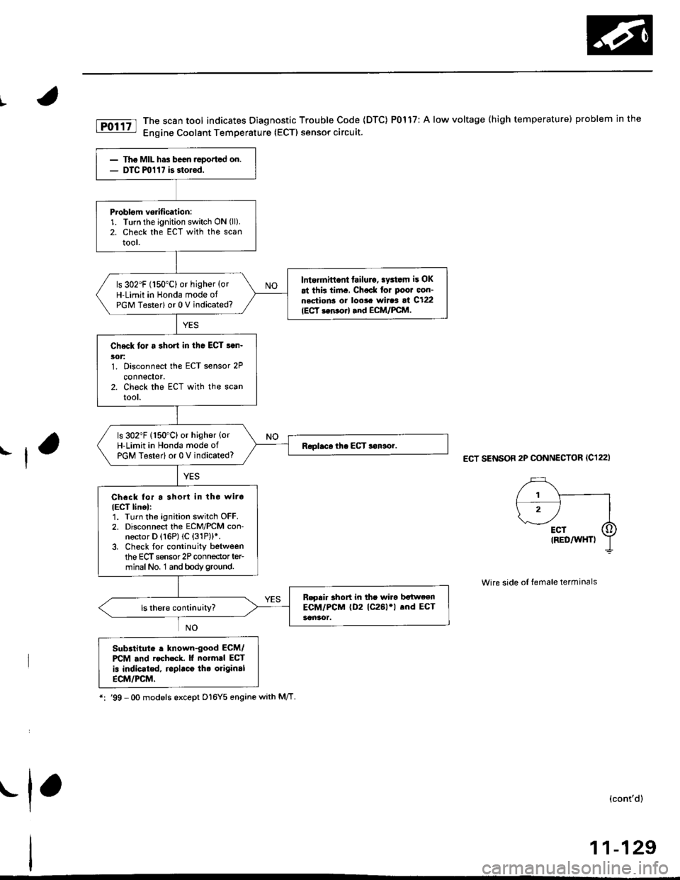
fD;r.tt The scan tool indicates Diagnostic Trouble Code (DTC) P0117: A low voltage (high temperature) problem in the|jg Engine Coolant Temperature (ECTI sensor circuit.
ECT SENSOR 2P CONNECTOR (C122I
Wire side of female terminals
Substitute . lnown-good ECM/PCM .nd rocheck. It normrl ECT
is indic.ted, replaco the original
ECM/PCM,
*:'99 -Oo models except D16Y5 enginewith M/T
(cont'd)
11-129
The MIL has been ,eported on.DTC ml 1 7 is storod.
Problom vorification:1. Turn the ignition switch ON (ll).
2. Check the ECT with the scantool.
Intermittont failulo, sy3tom it OK
at thk tim., Chock for Poor oon-n.ctions or loo!. wiraa at C122IECT 3en orl and ECM/FCM.
ls 302"F (150"C) or higher {orH-Limit in Honda mode ofPGM Tester) or 0 V indicated?
Check toJ a short in the ECT s.n-5('t:1. Disconnect the ECT sensor 2P
connector.2. Check the ECT with the scanrool.
ls 302"F (150"C) or higher {orH-Limit in Hond6 mode ofPGM Testerl or 0 V indicated?
Check for a 3hort in tho wiro
IECT linel:1. Turn the ignition switch OFF.2. Disconnect the ECM/PCM con-nector D (16P) (C {31P))*.3. Check for continuity betweenthe ECT sensor 2P conneclor ter-minalNo, 1 and bodyground.
B.gair short in the wiro bltweenECM/PCM (D2 (C261'l .nd ECT
.1,
Page 400 of 2189

PGM-FI System
t
I
Engine Coolant Temperature (ECT) Sensor
('99 - 00 Models except Dl6Y5 engine with M/Tl
The scan tool indicates Diagnostic Trouble Code (DTC) P0118: A high voltage (low temperature) problem in the
Engine Coolant Temperature (ECT) sensor circuit.
ECT SENSOR 2P CONNECTOR {C122)
ECT(RED/Wr{T)
JUMPER IVIRE
sG2{GRN/BLK)
wire side of female terminals
ECM/PCM CONNECTOB C 131PI
The MIL has been reported on,
oTC P0118 is stored.
Problem verilication:1. Turn the ignition switch ON (ll).
2. Check the ECT with the scan
tool.
lntormittent failuro, systom is OK
at thb timo. Check lor poor con'nections or 10036 wiraa at C122
{ECT ssnsorl and ECM/rcM.
ls -4'F (-20"C) or less lor L-Limit
in Honda mode o{ PGM Tester) or
5 V indicated?
Check for an open in the Efi sen'
sori1. Disconnect the ECT sensor 2P
connector,2. Connect the ECT sensor 2P
connector terminals No, 1 andNo. 2 with a jumper wire.3. Check the ECT with the scantool.
ls -4"F 1-20"C) or less (or L-Limit
in Honda mode of PGM Tester) or
5 V indicated?
Check for sn open in the wires
IECT. SG2 linesl:1. Turn the ignition switch OFF.2. Connect ECM/PCM connectorterminals C18 and C26 with ajumper wire.3. Turn the ignition switch ON (ll).
4. Check the ECT with lhe scantooi.
Rspair opon in th6 wiros bstwoon
ECM/PCM (Cl8, C26l and ECT
3ensot.
ls -4'F {-20"C) or less (or L-Limit
in Honda mode of PGN4 Tester) or
5 V indicated?
Substitute 6 known-good ECM/PCM and recheck. l{ no.mal EcT
is indicatod, .eplace the originalECM/PCM.
JUMPER WIRE
Wire side of female terminals
11-131
Page 460 of 2189
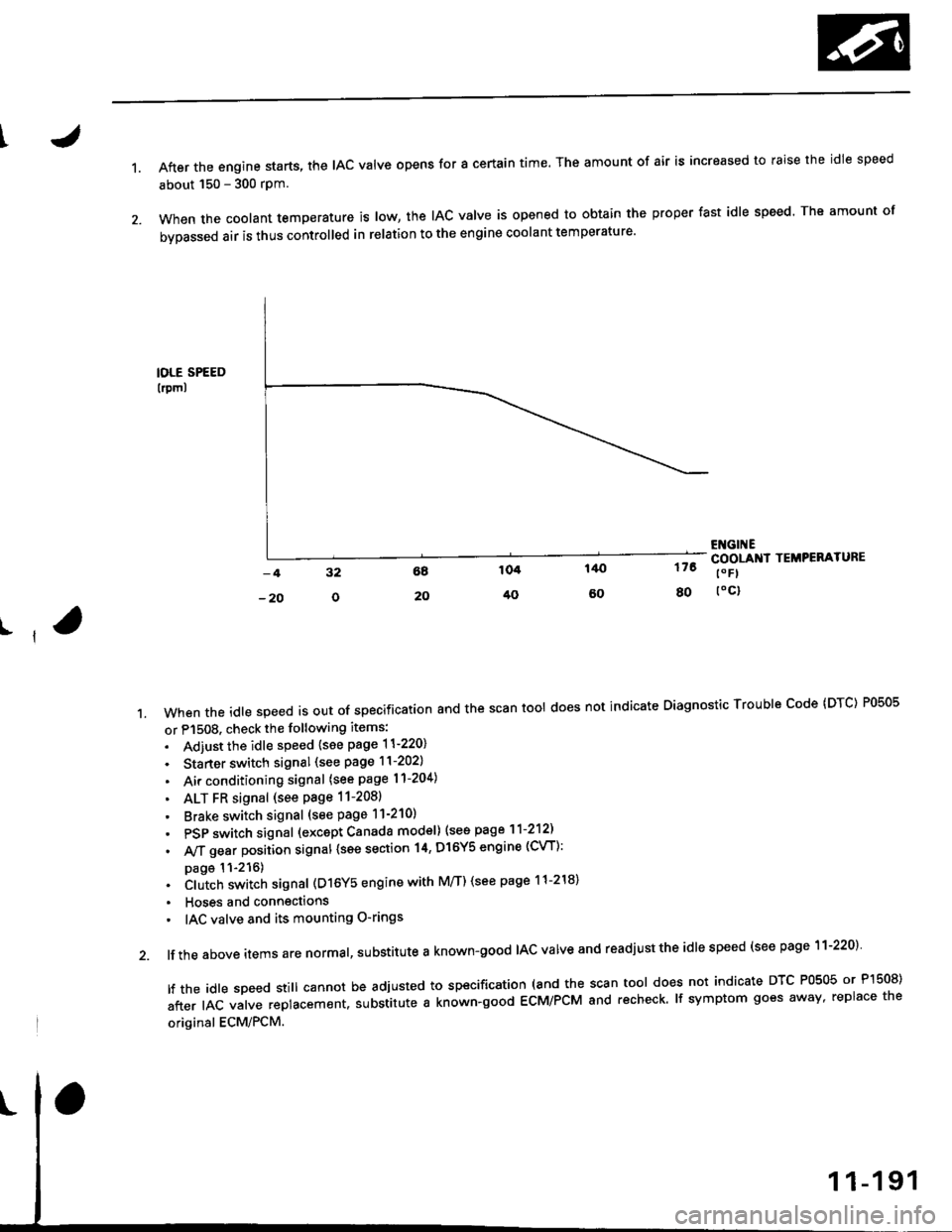
1.After the engine starts, the lAc valve opens for a certain time. The amount of air is increased to raise the idle speed
about 150 - 300 rpm.
When the coolant temperature is tow, the IAC valve is opened to obtain the proper fast idle speed. The amount of
bypassed air is thus controlled in relation to the engine coolant temperature'
IOLE SPEED
lrpml
176
80
ENGI ECOOLANI TEMPERATURE
t" Fl
toc)
ll
't.Whentheid|espeedisoutofspeciiicationandthescantoo|doesnotindicateDiagnosticTroub|ecode(DTc)P0505
or P1508. check the following items:
. Adiust the idle speed {see page 11-220}
. Starter switch signal (see page 11-202)
. Air conditioning signal (see page l1-204)
. ALT FR signal (see Page 11-2081
' Brake switch signal (see page 11-210)
. PSP switch signal (excapt Canada model) (see page 11-212)
. A,/T gear position signal {see section 14, Dl6Y5 engine (CVT):
page 11-216). Clutch switch signal (D16Y5 engine with M/T) (see page 11-218)
. Hoses and connections
' IAC valve and its mounting O-rings
lf the above items are normal, substitute a known-good IAC valve and readjust the idle speed (see page 11-220)
|ftheid|espeedsti||cannotbeadjustedtospecification(andthescantoo|doesnotindicateDTcP0505orP]50S)
after IAC valve replacement. substitute a known-good ECM/PCM and recheck. lf symptom goes away, replace the
original ECM/PCM.
Page 461 of 2189
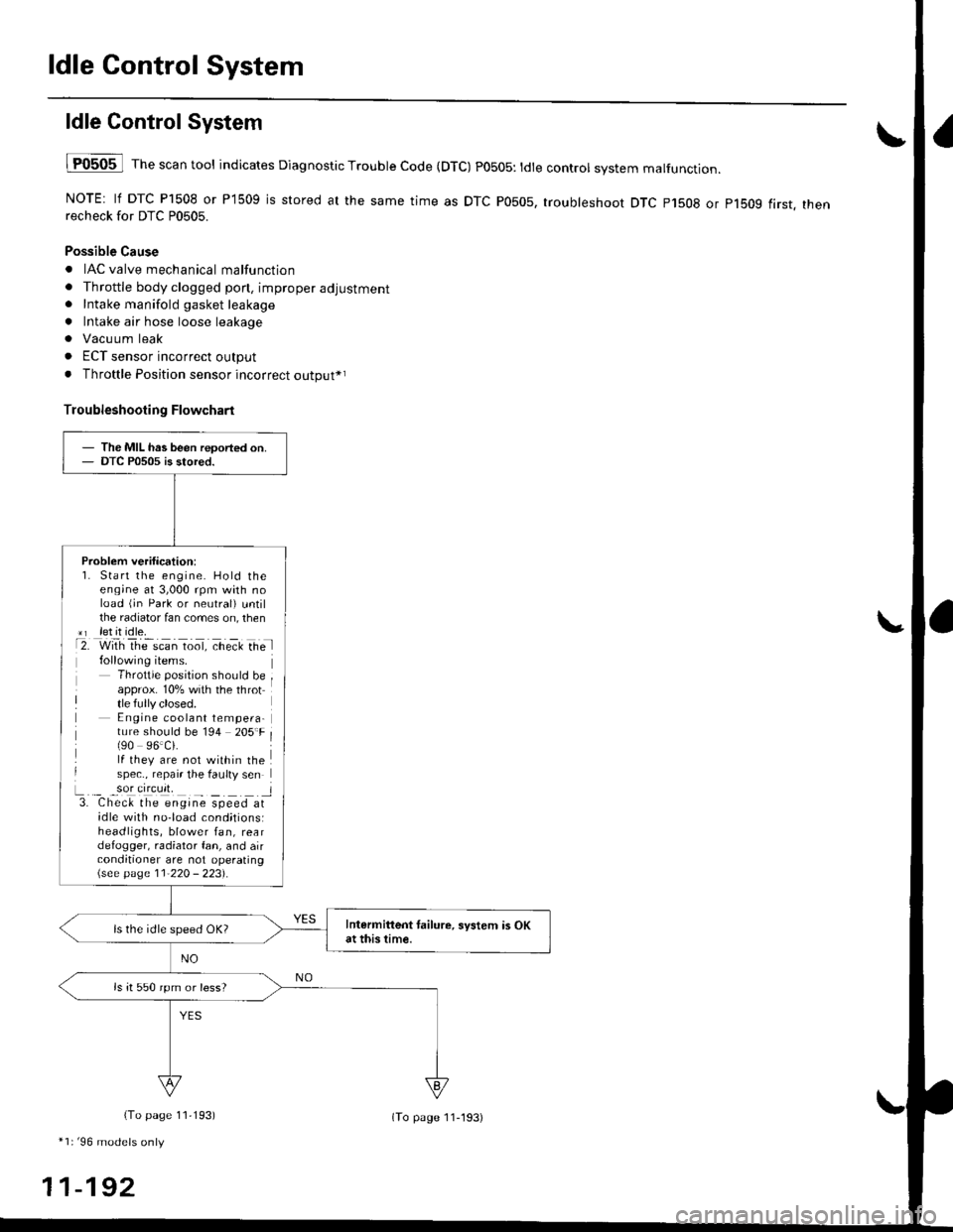
ldle Control System
ldle ControlSystem
lF0505 l Th" """n tool indicates Diagnostic Trouble Code (DTC) PO5O5: tdte controt system malfunction.
NOTE: lf DTC P1508 or P1509 is stored at the same time as DTC P0505, troubleshoot DTC p1508 or p1bog first. thenrecheck for DTC P0505.
Possible Cause
. IAC valve mechanical malfunction
. Throttle body clogged pon, improper adjustment. Intake manifold gasket leakage
. Intake air hose loose leakage
. Vacu um leak
. ECT sensor incorrect output
. Throttle Position sensor incorrect output*r
Troubleshooting Flowchart
The MIL has been reoorted on.DTC P0505 is stored.
Problem verification:1. Start the engine. Hold theeng;ne at 3,000 rpm with noload (jn Park or neutral) untilthe radiator fan comes on, then*r let it idle.t2. with rhe scan toot, ct'eit Ge l
Throttle position should beapprox. 10% with the throttle fully closed.E ngine coolant tempera-ture should be 194 205'F(90 96.Ci.lf they are not within thespec., repair the faulty sen
L._ _9oI9[cr]41 l3. Chec& the engine speed atidle with no-load cond;tionsiheadlights, blower fan, reardefogger, radiator fan, and airconditioner are not operating\see page l1-22O - 223).
Intermittent tailure, system is OKat this time.ls the idle speed OK?
ls it 550 rpm or less?
(To page 11,193)
*1r'96 models only
11-192
(To page ll-193)
Page 491 of 2189
ldle Control System
ldle Speed Setting (cont'dl
Inspeqtion/Adiustment
38 D16Y5 engine whh M/T,'99 - 00 81642 engine
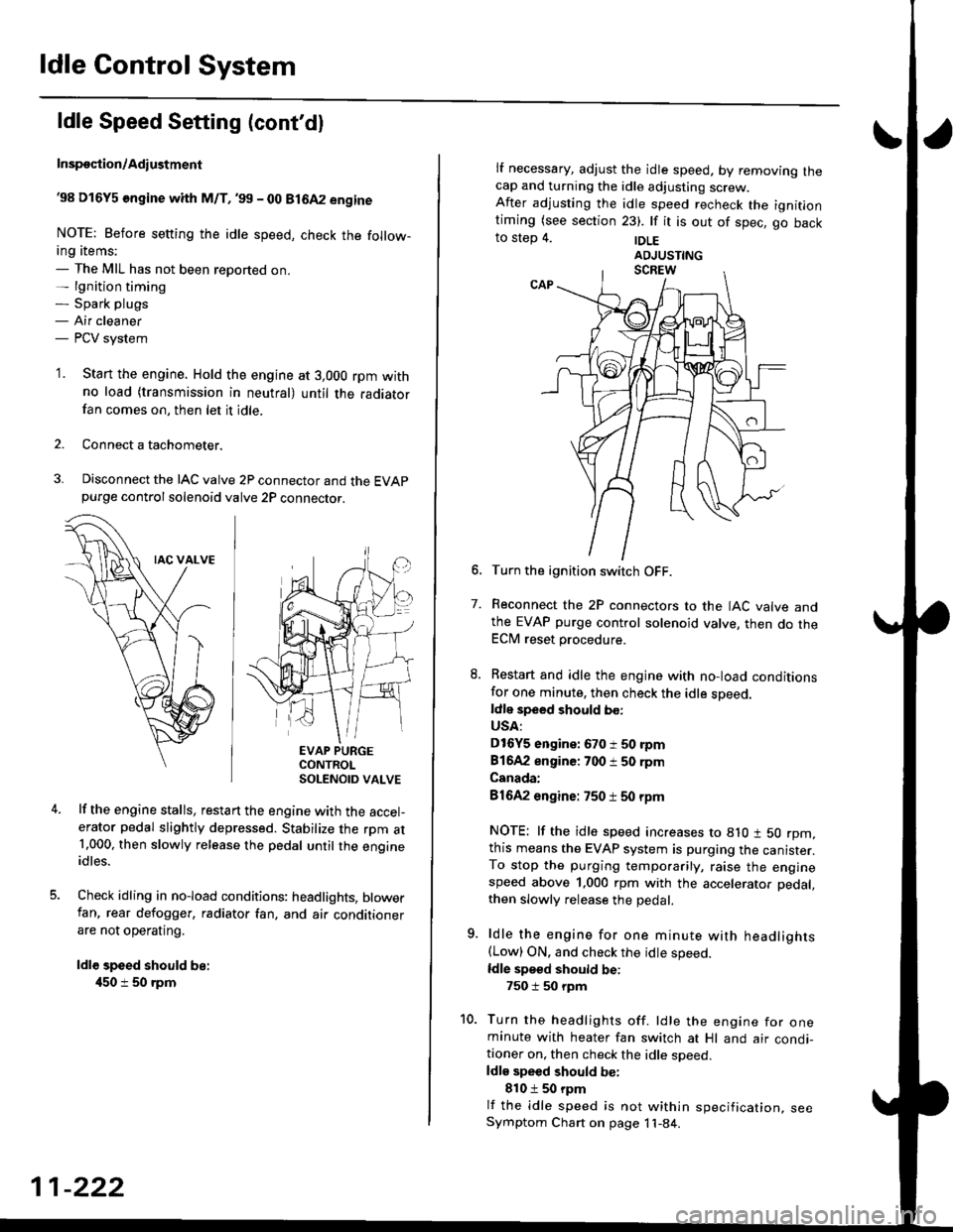
NOTE: Before setting the idle speed, check the follow-ing items;- The MIL has not been reported on.- lgnition timing- Spark plugs- Air cleaner- PCV system
'1. Start the engine. Hold the engine at 3,000 rpm withno load (transmission in neutral) until the radiatorfan comes on, then let it idle.
Connect a tachometer.
Disconnect the IAC valve 2P connector and the EVAPpurge controlsolenoid valve 2P connector.
EVAP PURGECONTROLSOLENOID VALVE
lf the engine stalls, restart the engine with the accel-erator pedal slightly depressed. Stabilize the rpm at1.000, then slowly release the pedal until the engineidles.
Check idling in no-load conditions: headlights, blowerfan, rear defogger, radiator fan, and air conditionerare not operating.
ldl€ speed should be:
450 i 50 rpm
11-222
lf necessary, adjust the idle speed, by removrng lnecap and turning the idle adjusting screw.After adjusting the idle speed recheck the ignitlontiming (see section 23). lf it is out of spec, go backto step 4. |DLE
6. Turn the ignition switch OFF.
7. Reconnect the 2P connectors to the IAC valve andthe EVAP purge control solenoid valve, then do theECM reset procedure.
8. Restart and idle the engine with no-load conditionsfor one minute, then check the idle sDeed.ldle speed should bo:
USA:
D16Y5 engine: 670 i 50 rpm
81642 engine: 700 i 50 rpm
Canada:
81642 engine: 750 t 50 rpm
NOTE: lf the idle speed increases to 8lO t 50 rpm,this means the EVAP system is purging the canister.To stop the purging temporarily, raise the enginespeed above 1,000 rpm with the accelerator pedal,
then slowly release the pedal.
9. ldle the engine for one minute with headlights(Low) ON. and check the idle speed.
ldle speed should be:
750 i 50 rpm
10. Turn the headlights off. ldle the engine for oneminute with heater fan switch at Hl and air condi-tioner on, then check the idle soeed.ldls speed should be:
810 t 50 rpm
lf the idle speed is not within specification, seeSymptom Chart on page 11-84.