1999 HONDA CIVIC Engine
[x] Cancel search: EnginePage 591 of 2189

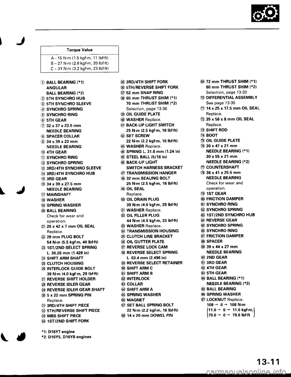
Torque Value
A - 15 N.m (1.5 kgf.m, 1'1 lbf.ft)
B - 27 N.m (2.8 kgf.m. 20 lbift)
C - 31 N.m {3.2 kgnm, 23 lbift)
\
O BALL BEARING (*T)
ANGULAR
BALL BEARING {*2I
O 5TH SYNCHRO HUB
O 5TH SYNCHRO SLEEVE
€) SYNCHRO SPRING
o SYNCHRO B|NG
@ 5TH GEAR
@ gz xgt x 23.5 mm
NEEDLE BEARING
@ SPACER COLLAR
@34x39x23mm
NEEDLE BEARING
(D 4TH GEAR
O SYNCHRO RING
C) SYNCHRO SPRING
CO 3RD/4TH SYNCHRO SLEEVE
@ 3RD/4TH SYNCHRO HUB
(} 3RD GEAR
@34x39x27.5mmNEEDLE BEARING
G) MAINSHAFT
G) WASHER
@ SPRING WASHER
@ BALL BEARING
Check for wear and
operation.(E 26x42x7 mm OIL SEAL
Replace.
@ 28 mm PLUG BOLT
5,1 N.m {5.5 kgf'm, /t0 lbt'ft)
@ lsT/zND SELECT SPRING
L. 36.26 mm (1./P8 in)
@ SHIFT ARM SHAFT
@ CLUTCH HOUSING
@ INTEELOCK GUIDE BOLT
39 N.m (4.0 kgf.m, 29 lbf.ftl
@ REVERSE SHIFT HOLDER
@ REVERSE IDLER GEAR
@ REVERSE IDLER GEAR SHAFT
@ 5 x 22 mm SPRING PIN
Replace.
@ 3RD/4TH SHIFT PIECE
@ 5TH/REVERSE SHIFT PIECE
@ MBS SHIFT PIECE
@ 1ST/2ND SHIFI FORK
*1:D16Y7 engine*2: D16Y5, D16Y8 engines
@ 3RD//|TH SHIFT FORK
@ 5TH/REVERSE SHIFT FORK
@ 52 mm SNAP RING
@ 65 mm THRUST SHIM (*11
70 mm THRUST SHIM (*21
Selection, page 13-36
@ OIL GUIDE PLATE
@ wASHER Replace.
@ BACK.UP LIGHT SWITCH
25 N.m (2.5 kgf'm, 18 lbf'ft)
@ sET SCREW
22 N.m {2.2 kgf.m, 16 lbl.ft}
@ WASHER Replace.
@D SPRING 1.31.6 mm (1.2,1inl
@ STEEL BALL 15/16 in)
@ BACK-UP LIGHT
SWITCH HARNESS BRACKET
@ TRANSMISSION HANGER
@ 32 MM SEALING BOLT
25 N.m (2.5 kgf.m, 18 lbt'ft)
@ OIL SEAL
Replace.
@ OIL DRAIN PLUG
39 N.m (4.0 kgf.m, 29 lbf.ft)
@ WASHER Replace.
@} OIL FILLER PLUG
44 N.m (4.5 kgf.m, 33 lbf'ftl
@ WASHER Replace.
@) TRANSMISSION HOUSING
€) CLUTCH LINE BRACKET
@ OIL GUTTER PLATE
@ REVERSE LOCK CAM
@ REVEBSE SELECT SPRING
L. 63.4 mm {2.,196 in)
@ REVERSE SELECT RETAINER
@ SHIFT ARM C
@ SHIFT ARM B
@ INTERLoCK
@ COLLAR
@ SHIFT ARM A
@ SPRING WASHER
@ MAGNET
@ sET BALL SPRING BOLT
22 N.m (2.2 kgf.m, 16 lbf.ftl
@ 14 x 20 mm DOWEL PIN
@ 72 mm THRUST SHIM l*11
80 mm THRUST SHIM (*21
Selection, page '13-33
@ DIFFERENTIAL ASSEMBLY
See page 13-30
@ 14 x 25 x 17.5 mm OIL SEAL
Replace.
@ 35 x 56 x 8 mm OIL SEAL
Replace.
@ SHIFT ROD
@ BOOr
@ OIL GUIDE PLATE
@30x47x21 mm
NEEDLE BEARING (* 1}
30x55x21 mm
NEEDLE BEARING {'2)
@ COUNTERSHAFT
@36x41 x 25.5 mm
NEEDLE BEARING
Check for wear and
operatron.
@ lsT GEAR
@ FRICTION DAMPER
@ SYNCHRO RING
@ SYNCHRO SPRTNG
@ lST/2ND SYNCHRO HUB
@ REVERSE GEAR
@ SYNCHRO SPRING
@ SYNCHRO RING
@ FRICTION DAMPER
@ SPACER
@39x4lx27mm
NEEDLE BEARING
@ 2ND GEAR
@ 3RD GEAR
@ 4TH GEAR
@ sTH GEAR
@) BALL BEARING {* 1}
NEEDLE BEARING (*2}
@ BALL BEARING
@) SPRING WASHER
@ LoCKNUT Replace.
108 - 0- 108 N.m
ftt.o* o- 1r.o kst.m,l
179.6- 0- 79.6 rbtft I
13-1 1
Page 595 of 2189

Mainshaft Assembly
I
lndex
Note the following during reassembly:
. The 3rd/4th and sth svnchro hubs are installed with a press
. Install the angular ball bearing with the thin-edge outer race facing the sth synchro hub
. Install the ball bearing with the ball cage facing up
prior to reassembling, clean all the parts in solvent, dry them and apply lubricant to all contact surfaces the 3rd/4th
and sth svnchro hubs.
Ballcage faces uP.
Thin edge of outerrace laces down.
3RD/4TH SYNCHRO SLEEVE
page 13'27
SYNCHRO SPRINGSYNCHRO RINGInspection,page 13-28
BALL BEARING {*1)ANGULAR BALL BEARING ('2)
Check for wear and operataon.Note the direction ot installation
5TH SYNCHROSLEEVElnspection, page 13-27
SYNCHRO HUB
SYNCHRO RINGInspection, pase 13 28
sTH GEARInspection, page 13-17
3RD GEARlnspection, page 1 3-1 6
34 x 39 x 27.5 mmNEEDLE BEARINGCheck for wearano opetaflon,
MAINSHAFTInspection, page 13-18
CHAMFEB
32 x 37 x 23.5 mmNEEDLE BEARINGCheck for wear andoperation.SPACER COLLABInspection, page 1316
34x39x23mmNEEDLE EEARINGCheck for wearand operation,
4TH GEARrnspeclron,
*1: D16Y7 engine*2: D16Y5, D16Y8 engines
page 13'16RINGInspectaon, page 13 28
SPRING
13-15
Page 600 of 2189

Countershaft Assembly
Index
I.r
NOTE:
-re
The 3rd, 4th, and sth gears are installed with a press.
Prior_to reassembling, clean all the parts in solvent, dry them and apply lubricant to all contact surfaces except the3rd, 4th, and 5th gears.
Snap ring groove faces up.
LOCKNUT Replace.108-O- 108 N.m
I 11.0-O-11.0 kst.ml
I 79.6-0- 79.6 lbt.ft I
SYNCHRO SPRING
SYNCHRO RINGInspectaon, page 13-28
FRICTION DAMPER
Thin edge ol outerrace faces down.
Check for wear andoperatron,
/ BALL EEAR|NG t*1)
t NEEDLE BEARTNG (.2)
Check for wearand operatron,
WASHERBEARING
GEAR
4TH GEAR
3RD GEAR2ND GEAR
FRICTION DAMPER
SYNCHRO SPRING
SYNCHRO RINGInspection, page 13-2836 x 41 x 25.5 mmNEEDLE BEARINGCheck for wear and operataon.
Inspection, page 13-23
1ST GEARlnspection, page 13 21, 28lnspection, page 13-21, 2839x44x27m�mNEEDLE BEARIfI'GCheck for wear andoperation.
SPACER COLLARInspection, page 13-21
REVERSE GEARlnspection, page 13 27
1ST/2ND SYNCHRO HUB
*1: D'16Y7 engine*2: D16Y5, D16Y8 engines
13-20
Page 604 of 2189

Countershaft Assembly
Reassembly (cont'd)
4. Suppon the countershaft on a steel block as shownand install 3rd gear using the special tools and apress.
PRESS
35 mm l.o.07746-0030400
5. Install 4th gear using the special tools and a press.
DRlvER. 40 mm
DRIVER, 40 mm LO.07746 -0030100
ATTACHMENT,
07746- 0030100
ATTACHMENT,
DRIVER, 40 mm l.D.07746-0030100
ATTACHMENT,30 mm l.D.
35 mm LO.07746-0030400
6. Install 5th gear using the special tools and a Dress.
07746-00303005TI{ GEAR
.g
7. Install the bearings in the direction shown using thesDecialtools and a oress.
CAUTION: Install ths bearings with a maximumpressure ot 7.8 kN {800 kgt, 5,786 lbfl.
ATTACHMENT,30 mm l.D.07745 - q'303tl)
*1: 016Y7 engine*2: D16Y5, D16Y8 enginesThin edge of outerrace faces down,
8. Securely clamp the countershaft assemblv in
bench vise with wood blocks.
LOCKNUT
108+0r108N.m(11.0 * 0 - 11.0 kgt m. 79.6 - 0 * 79.6 tbf.ft)
Install the spring washer, tighten the locknut, thenstake the locknut tab into groove.
/rt-\
srySnap ring
lacss up.
\J
Page 613 of 2189

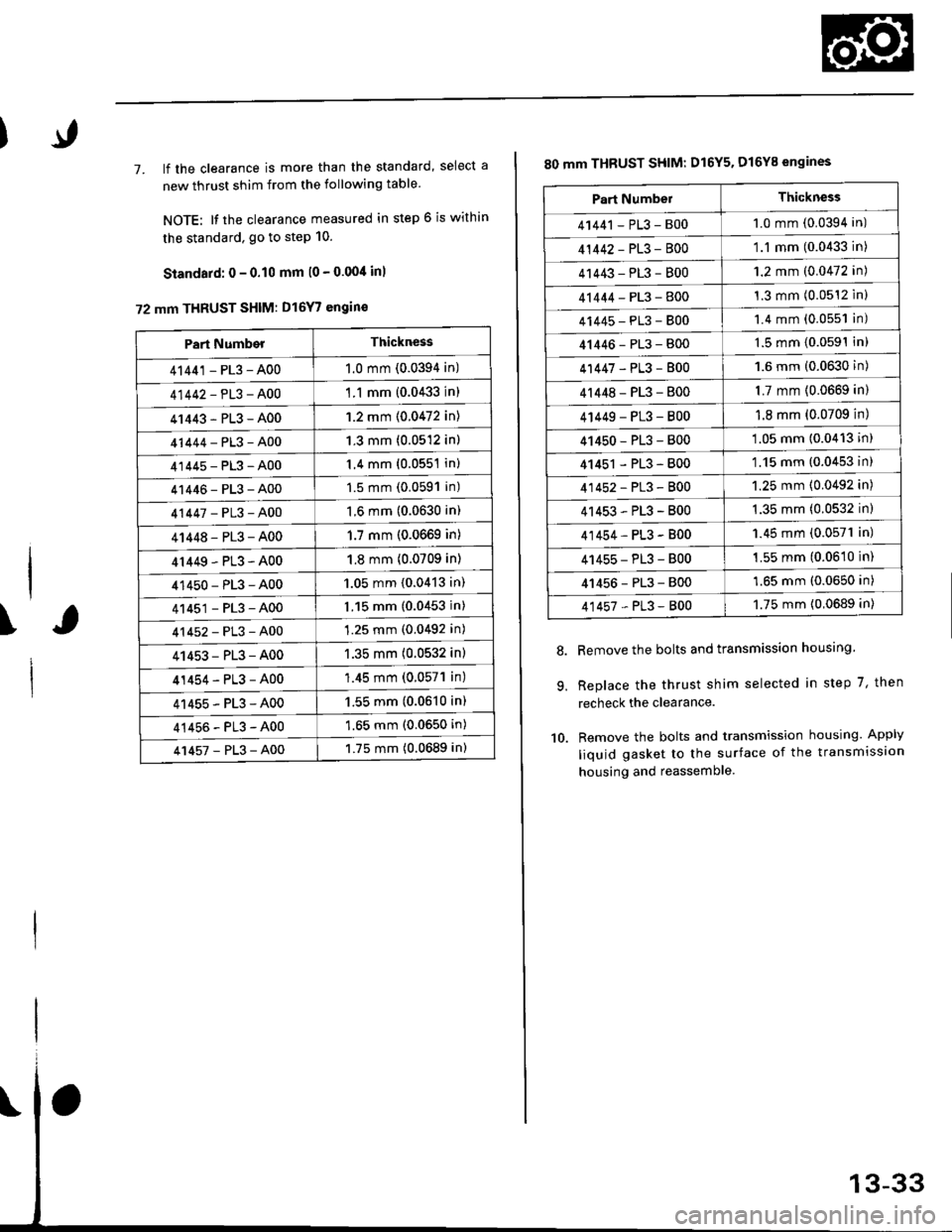
7. lf the clearance is more than the standard, select a
new thrust shim from the following table
NOTE: It the clearance measured in step 6 is within
the standard. go to step 10.
Standard: 0 - 0.10 mm l0 - 0.00/t inl
72 mm THRUST SHIM: D16Y7 engin€
\
Part NumberThickness
41441 - PL3 - A001.0 mm (0.0394 in)
41442-PL3-A00'1 .1 mm {0.0433 in)
41443-PL3-A001.2 mm {0.0472 in)
41444-PL3-A001.3 mm (0.0512 in)
41445-PL3-A001.4 mm (0.0551 in)
41446-PL3-A001.5 mm (0.0591 in)
41447-PL3-A001.6 mm (0.0630 in)
41448-PL3-A001.7 mm (0.0669 in)
4r449-PL3-A001.8 mm (0.0709 in)
41450-PL3-A001.05 mm {0.0413 in)
41451-PL3-A001.15 mm (0.0453 in)
41452-PL3-A001.25 mm (0.0492 in)
41453-PL3-A001.35 mm (0.0532 in)
41454-PL3-A00'1.45 mm (0.057'l in)
41455-PL3-A001.55 mm (0.0610 in)
41456-PL3-A001.65 mm (0.0650 in)
41457-PL3-A001.75 mm (0.0689 in)
80 mm THBUST SHIM: D16Y5. D16Y8 engines
Remove the bolts and transmission housing.
Replace the thrust shim selected in step 7, then
recheck the clearance.
Remove the bolts and transmission housing. Apply
liquid gasket to the surface of the transmission
housing and reassemble
8.
9.
10.
Part NumbelThickness
41441 - PL3 - B001.0 mm (0.0394 in)
41442-PL3-8001.1 mm (0.0433 in)
41443-PL3-8001.2 mm (0.0472 in)
41444-PL3-8001.3 mm (0.0512 inl
41445-PL3-8001.4 mm (0.0551 in)
41446-PL3-8001.5 mm (0.0591In)
41447-PL3-8001.6 mm (0.0630 in)
4r 448 - PL3 - 8001.7 mm (0.0669 in)
4 t449 - PL3 - 8001.8 mm (0.0709 in)
41450-PL3-800'1.05 mm (0.0413 in)
41451 - PL3 - 800'1.15 mm (0.0453 in)
41452-PL3-8001.25 mm (0.0492 in)
41453-PL3-B001.35 mm (0.0532 in)
41454-PL3-B001.45 mm (0.0571 in)
41455-PL3-B001.55 mm (0.0610 in)
41456-PL3-8001.65 mm (0.0650 in)
41457-PL3-8001.75 mm {0.0689 in)
Page 615 of 2189

Cou ntershaft
1. Remove the needle bearing using the special tool as
shown. then remove the oil guide plate
3/g " -16 SLIDE HAMMER
{Commercially available)
PULLER, 25-40 mm07736-AO1000A
\
2. Install the oil guide Plate, then
bearing into the clutch housing
tools as shown.
d rive the needle
using the special
'1: ATTACHMENT, 42 x 47 mm
07746-0010300*2: ATTACHMENT, 52 x 55 mm
07746 -0010400
ORIVER07749 -0010000
CLUTCHHOUSING
NEEOLE BEAFING
GUIDE PLATE
NEEOLE BEARING
*1: D16Y7 enqine*2: D16Y5, D16Y8 engines
OIL GUIDE PTATE
13-35
Page 616 of 2189

Mainshaft Thrust Shim
Adjustment
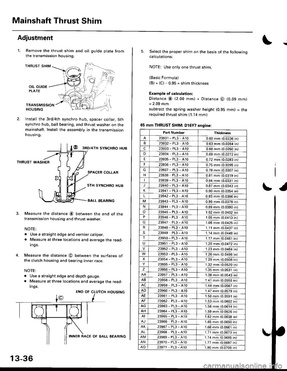
Remove the thrust shim and oil
the transmission housing.
1.gu ide plate from
THRUST SHIM
OIL GUIDEPLATE
TBANSMISSIONHOUSING
Install the 3rd/4th synchro hub, spacer collar, 5th
synchro hub, ball bearing, and thrust washer on themainshaft. Install the assembly in the transmission
h ousing.
@ gnol+lx syNcHRo HUB
THRUST WASHER
SPACER COLLAR
4.
Measure the distance @ between the end of thetransmission housing and thrust washer.
NOTE:
. Use a straight edge and vernier caliper.. Measure at three locations and average the read-
Ings.
Measure the distance @ between the surfaces ofthe clutch housing and bearing inner race.
NOTE:
. Use a straight edge and depth gauge.
. Measure at three locations and average the read-
Ings.
sTH SYNCHRO IIUB
BALL EEARING
CLUTCH
L
HOUSINGENO OF
13-36
INNER RACE OF BALL AEARING
\
5.Select the proper shim on the basis of the followingcalculations:
NOTE: Use only one thrust shim.
(Basic Formula)(B) + {C). 0.95 = shim thickness
Example of calculation:
Distance @ (2.00 mm) + Distance @= 2.09 mm
subtract the spring washer height (0.95
required thrust shim (1.14 mm)
65 mm THRUST SHIM: D16Y7 engine:
(0.09
mm)
mm)
= tne
r1
Part NumborThickness
23931 - PL3 A100.60 mm (0.0236 in)23932 - PL3 A100.63 mm 10.0284 in)c23933 - PL3 A100.66 mm {0.0260 iniD23934 PL3 - A100.69 mm (0.0272 in)
E23935-PL3-4100.72 mm 10.0283 in)
F23936-PL3-4100.75 mm 10.0295 in)G23937-PL3-A100.78 mm {0.0307 in}
23938 PL3 - A100.81 mm (0.0319 in)I23939 - PL3 At00.84 mm (0.0331 in)J23940-PL3-Ar00.87 mm (0.0343 in)
23941 - PL3 - A100.90 mm (0.0354 in)
L23942 - PL3 A100.93 mm (0.0366 in)
23943-PL3-A100.96 mm (0.0378 in)N23944 PL3 - A100.99 mm 10.0390 in)
o23945-PL3-A101.02 mm {0.0402 in}23946 - PL3 A101.05 mm (0.0413 in)o23947 PL3 - 4101.08 mm (0.0425 in)R23948-PL3-A101.11mm (0.0437 in)s23949 PL3 - A101.14 mm {0.0449 in}T23950-PL3-A101.17 mm (0.0461 in)
U23951 PL3 - A101.20 mm (0.0472 in)
23952-PL3-Ar01.23 mm {0.0484 in)
23953-PL3-A101.26 mm {0.0496 in}X23954 - P13, A101.29 mm (0.0508 in)23955 - PL3 A101.32 mm (0.0520 in)z23956-PL3-Ar01.35 mm {0.0531 in)
23957-PL3-A101.38 mm (0.0543 in)
AB239s8 - PL3 A101.41 mm (0.0555 in)AC23959 PL3 - A101.44 mm (0.0567 in)
AD23960 - PL3 A101.47 mm (0.0579 in)23961 - PL3 4101.50 mm (0.0591 in)23962 PL3 - A101.53 mm (0.0602 in)AG23963-PL3-4101.56 mm (0.0614 in)AH23964 - PL3 A101.59 mm (0.0626 in)AI23965-PL3-A101.62 mm {0.0638 in)
23966 PL3 - A101.65 mm (0.0650 in)AK23967-PL3-A101.68 mm {0.0661 in)
23968 PL3 - A101.71 mm {0.0673 in)23969-PL3-A101.74 mm (0.06a5 iniAN23970- PL3 -A101.77 mm (0.0697 in)AO23971 - PL3 - A101.80 mm 10.0709 in)
Page 627 of 2189

MaintenanceBack-up Light Switch
\
Transmission Oil
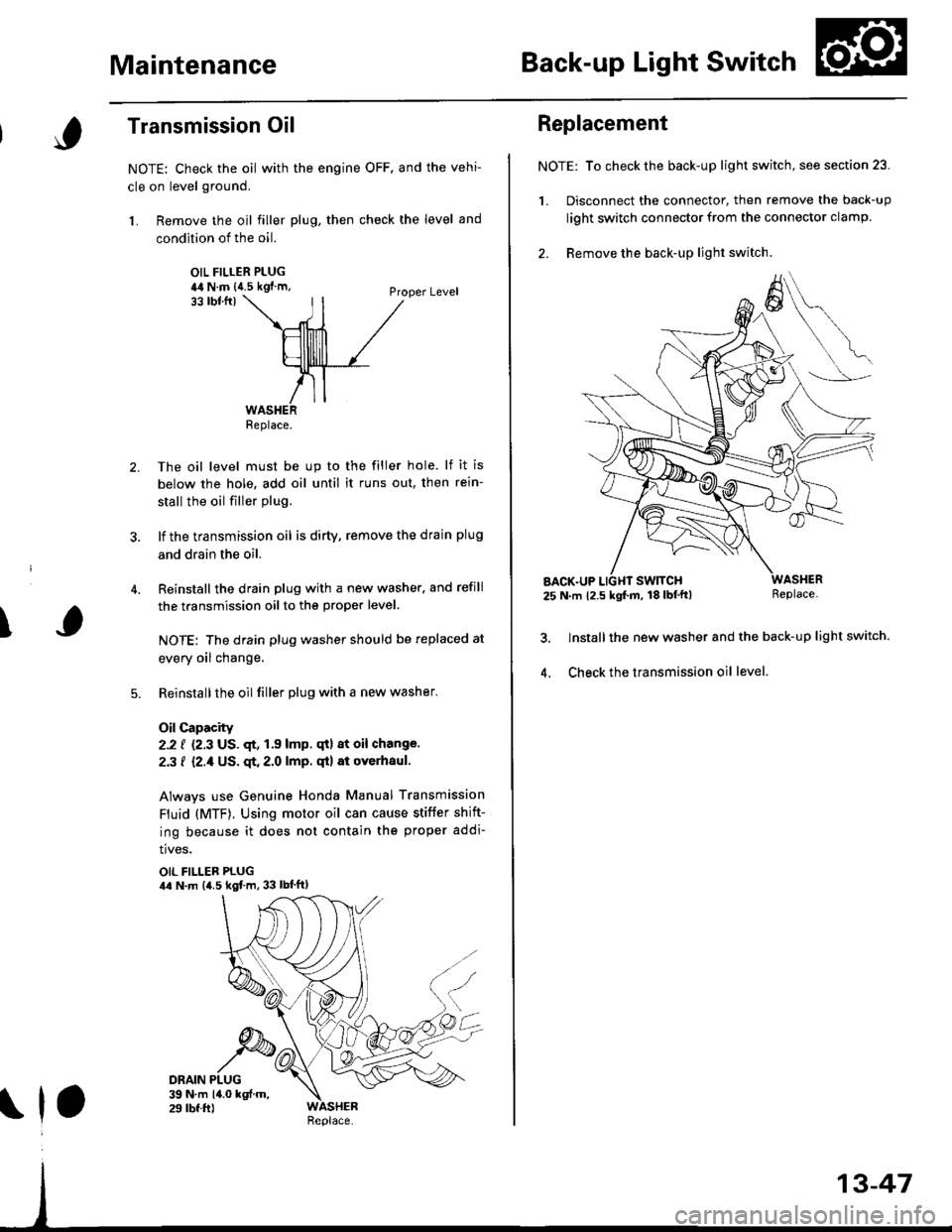
NOTE: Check the oil with the engine OFF. and the vehi-
cle on level ground.
1. Remove the oil filler plug, then check the level and
condition of the oil.
OIL FILLER PLUGia4 N.m {{.5 kgf'm,Proper Level33 tbtfrl
The oil level must be up to the filler hole. lf it is
below the hole, add oil until it runs out, then rein-
stall the oil filler plug.
lf the transmission oil is dirty, remove the drain plug
and drain the oil.
Reinstall the drain plug with a new washer. and refill
the transmission oil to the proper level.
NOTE: The drain plug washer should be replaced at
every oil change.
Reinstallthe oilfiller plug with a new washer.
Oil Capacity
2.2 f {2.3 US. qt, 1.9 lmp. qtl at oil change.
2.3 f {2./f US. qt. 2.0 lmp. qt} at overhaul.
Always use Genuine Honda Manual Transmission
Fluid (MTF). Using motor oil can cause stiffer shift-
ing because it does not contain the proper addi-
tives.
OIL FILLER PLUGila N.m {4.5 kgf.m, 33 lbt'ftl
Replace.
\1,
Replacement
NOTE: To check the back-up light switch, see section 23.
1. Disconnect the connector, then remove the back-up
light switch connector from the connector clamp.
2. Remove the back-up lighr switch.
AACK.UP25 N.m 12.5 kgf.m, 18 lbf'tt)Replace.
lnstall the new washer and the back-up light switch.
Check the transmission oil level.4.