1999 HONDA CIVIC Engine
[x] Cancel search: EnginePage 629 of 2189

9. Remove the three upper transmission mounting
bolts and lower starter motor mounting bolt.
'10. Remove the engine splash shieid.
TRANSMISSIONMOUNTINGBOLTS12 x 1.25 mm
6,1 N.m (6.5 kgd m, 47 lbf'ft|
STARTERMOTORMOUNTINGBOLT10 x 1.25 mm
a,t N.m 14.5 kgl.m.
33 tbf.trl
CONNECTOE
11. Disconnect the heated oxygen sensor (HO2S) con-
nector, then remove exhaust pip€ A.
H02S
SELF.LOCKING NUTReplace.8 r 1.25 mm16 N.m (1.6 kgf.m, 12lbf'ft)
Replace.10 x 1,25 mm54 N.m {5.5 kgf.m,'lll lbf.ft)
12. Remove the cotter pins and loosen the castle nuts,
then separate the ball joints from the lower arm
(see section 18).
13. Remove the right damPer fork.
10 x 1.25 mma3 N.m lil.a kgf.m, 32 lbf'ft| ,
SELF.LOCKING NUTR6place.12 x 1.25 mm6a N.m (6.5 kgl.m,47 rbf ft)
RIGHTDAMPERFORK
CASTI.T NUT12 x 1,25 mma9 - 59 N.m (5.0 - 6.0 kgtm,36 - i(t lbf.ftl
(cont'd)
!-
ria -11: \/-/
't'''-a
SPLASH SHIELD
13-49
Page 630 of 2189

Transmission Assembly
Removal(cont'd)
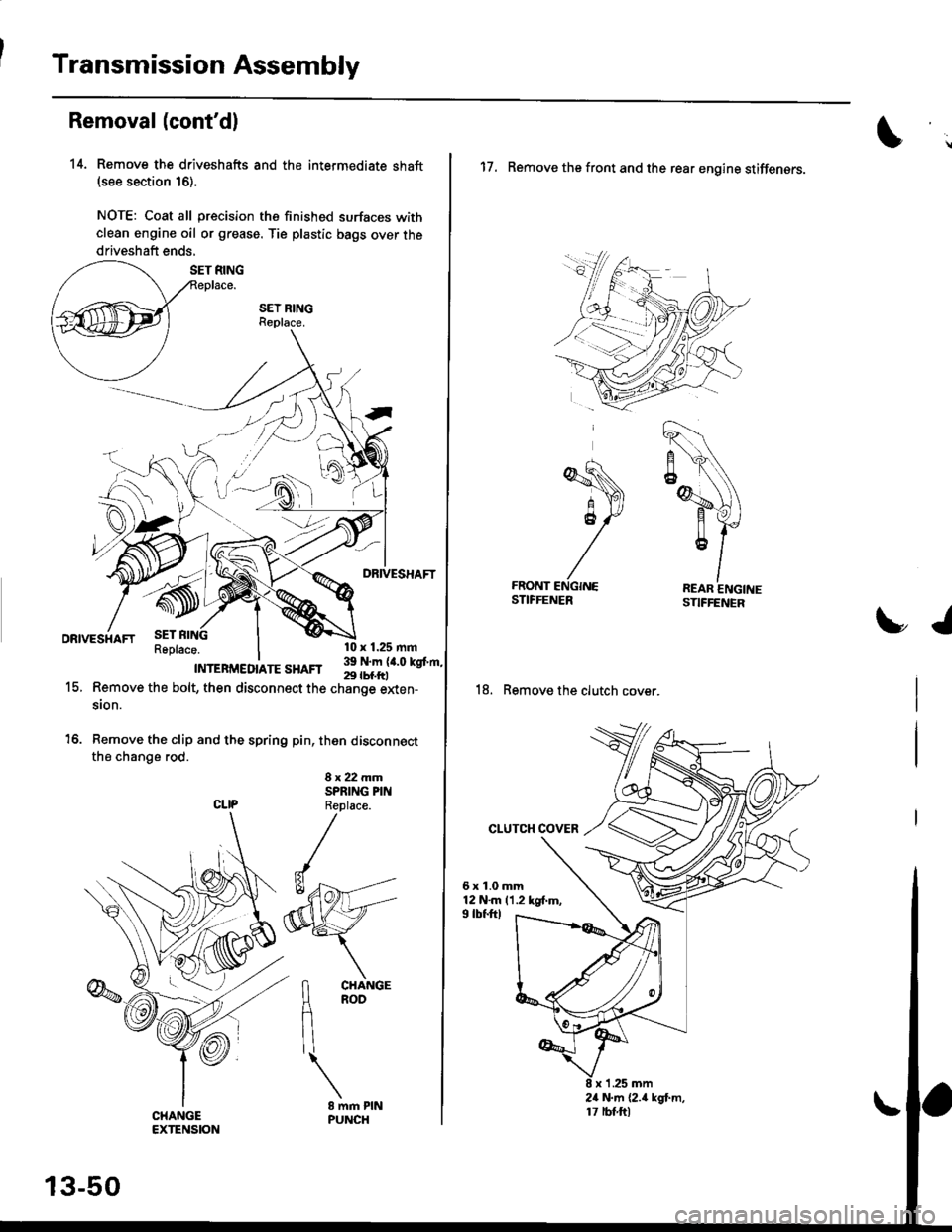
14. Remove the driveshafts and the intermediate shaft(see section 16).
NOTE: Coat all precision the finished surfaces with
clean engine oil or grease. Tie plastic bags over the
driveshaft ends,
Remove the bolt, then disconnect the change elden-
sion.
Remove the clip and the spring pin, then disconnectthe change rod.
8x22mmSPRING PINCLIP Replace.
15.
13-50
17. Remove the front and the rear engine stiffensrs.
18. Remove the clutch cover.
CLUTCH COVER
6x1.0mm12 N.m (1.2 kg{.m,9 tbf.ftl
x 'l .25 mm
tJ
24 N.m {2.4 kgt m,17 rbt ftl
Page 631 of 2189

)
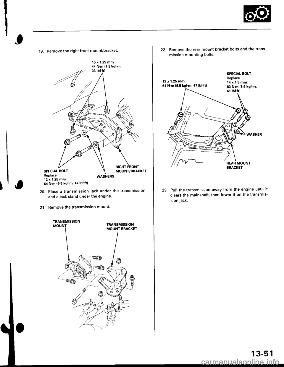
19. Remove the right front mounvbracket.
10 x 1 .25 mm,14 N.m {4,5 kgf.m,
WASHERS
20. Place a transmission jack under the transmission
and a jack stand under the engine.
21. Remove the transmission mount
SPECIAL BOLTReplace.12 x 1 .25 mm64 N.m 16.5 kgl'm, 47 lbf ftl
TRANSMISSION
3-51
22. Remove the rear mount bracket bolts and the trans-
mission mounting bolts
12 x 1.25 mm5{ N.m 16.5 kgf.m, 47 lbl.ft)
61
WASHER
23. Pull the transmission away from the engine until it
clears the mainshaft, then lower it on the transmis-
sion jack.
SPECIAL BOLTReplace.14 x 1.5 mm8il N.m (8.5 kgtm,
Page 681 of 2189

Description
The automatic transmission is a 3-element torque converter and a dual-shaft electronically controlled unit which provides
4 soeeds forward and 1 reverse.
Torque Convertel, Geats, and Clutches
The torque converter consists of a pump, turbine and stator, assembled in a single unit. They are connected to the engine
crankshaft so they turn together as a unit as the engine turns. Around the outside of the torque converter is a ring gear
which meshes with the starter pinion when the engine is being started. The entire torque converter assembly seryes as a
flywheel while transmiuing power to the transmission mainshaft.
The transmission has two parallel shafts: the mainshaft and the countershaft. The mainshaft is in Iine with the engine
crankshaft. The mainshaft includes the 1st, 2nd and 4th clutches, gears tor 2nd, 4th, reverse and lst (3rd gear is integral
with the mainshaft, while the reverse gear is integral with the 4th gear). The countershaft includes the 3rd clutch, and
gears for 3rd,2nd, 4th, reverse. 1st and park. The gears on the mainshaft are in constant mesh with those on the counter-
shaft. When certain combinations of gears in transmission are engaged by clutches. power is transmitted from the main-
shaft to the countershaft to provide E, ld, E, and E positions.
Electronic Control
The electronic control svstem consists of the Powertrain Control Module {PCM), sensors, a linear solenoid and four
solenojd valves. Shifting and lock-up are electronically controlled for comtonable driving under all conditions. The PCM is
located below the dashboard, under the front lower panel on the passenger's side
Hydraulic Control
The valve bodies include the main vatve body, the secondary valve body, the regulator valve body, the servo body and the
lock-up valve body through the respective separator plates, They are bolted on the torque converter housang
The main valve body contains the manual valve, the 1-2 shift valve. the 2nd orifice control valve, the CPB {Clutch Pressure
Back-up) valve, the modulator valve. the servo control valve, the relief valve, and ATF pump gears The secondary valve
body contains the 2-3 shift valve. the 3-4 shift valve, the 3-4 orifice control valve, the 4th exhaust valve and the CPC (Clutch
pressure Control) valve. The regulator valve body contains the pressure regulator valve, the torque converter check valve,
the cooler relief valve, and the lock-up control valve. The servo body contains the servo valve which is integrated with the
reverse shift fork, and the accumulators. The lock-up valve body contains the lock-up shift valve and the lock-up timing
valve. The linear solenoid and the shift control solenoid valve Ay'B are bolted on the outside of the transmission housing,
and the lock-up control solenoid valve Ay'B is bolted on the outside of the torque converter housing. Fluid from regulator
passes through the manual valve to the various control valves. The clutches receive fluid from their respective teed pipes
or internal hydraulic circuit.
Shift Control Mechanism
Input from various sensors located throughout the car determines which shift control solenoid valve the PCM will activate
Activating a shift control solenoid valve changes modulator pressure, causing a shift valve to move. This pressurizes a line
to one of the clutches, engaging that clutch and its corresponding gear, The shift control solenoid valves A and B are con-
trolled by the PCM.
Lock-up Mechanism
In ,Dt1 position, in 3rd and 4th. and in E position in 3rd, pressurized fluid is drained from the back of the torque converter
through a fluid passage, causing the lock-up piston to be held against the torque converter cover. As this takes place, the
mainshaft rotates at the same as the engine crankshaft. Together with hydraulic control, the PCM optimizes the timing of
the lock-up mechanism. The lock-up valves control the range of lock-up according to lock-up control solenoid valves A and
B, and linear solenoid. When lock-up control solenoid valves A and B activate, the modulator pressure changes The lock-
up control solenoid valves A and B and the linear solenoid are controlled by the PCM.
(cont'd)
14-3
Page 682 of 2189

Description
(cont'dl
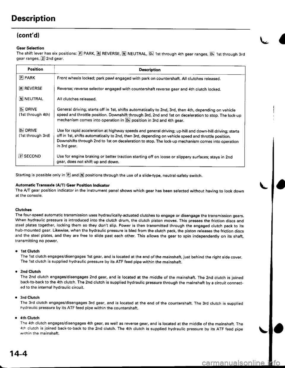
Gear Selection
The shift lever has six positions: E PARK. E REVERSE, N NEUTRAL, E 1st through 4th gear ranges, E 1st through 3rdgear ranges, @ 2nd gear.
Starting is possible only in E and E positions through the use of a slide-type, neutral-safety switch.
Automatic Transaxle (A/f, Gear Position Indicator
The Ay'T gear position indicator in the instrument panel shows which gear has been selected without having to look downat the console.
Clutch€s
The four-speed automatic transmission uses hydraulically-actuated clutches to engage or disengage the transmission gears.When hydraulic pressure is introduced into the clutch drum, the clutch piston moves. This presses the friction discs andsteel plates together, locking them so they don't slip. Power is then transmitted through the engaged clutch pack to itshub-mounted gear. Likewise, when the hydraulic pressure is bled from the clutch pack, the piston releases the friction discsand the steel plates, and they are free to slide past each other. This allows the gear to spin independently on its shaft,transmitting no power.
lst Clutch
The 1st clutch engages/disengages 1st gear, and is located at the end of the mainshaft, just behind the right sroe cover.The 1st clutch is supplied hydraulic pressure by its ATF feed pipe within the mainshaft.
2nd Clulch
The 2nd clutch engagegdisengages 2nd gear, and is located at the middle of the mainshaft. The 2nd clutch is joined
back-to-back to the 4th clutch. The 2nd clutch is supplied hydraulic pressure through the mainshaft by a circutr connect-ed to the internal hvdraulic circuit,
3rd Clutch
The 3rd clutch engages/disengages 3rd gear, and is located at the end of the countershaft. The 3rd clutch is suooliedhydraulic pressure by its ATF feed pipe within the countershaft.
ilth Clutch
The 4th clutch engages/disengages 4th gear, as well as reverse gear, and is located at the middle of the mainshaft. The4th clutch is joined back-to-back to the 2nd clutch. The 4th clutch is supplied hydraulic pressure by its ATF feed pipewith in the mainshaft.
\-a
PositionDe3cription
E PARK
E REVERSE
N NEUTRAL
E DRIVE
{1st through 4th)
Ei DRtvE('lst through 3rd)
B SECOND
Front wheels locked; park pawl engaged with pa* on countershaft. All clutches released.
Reverse; reverse selector engaged with countershaft reverse gear and 4th clutch locked.
All clutches released.
General driving; starts off in 1st, shifts automatically to 2nd, 3rd, then 4th, depending on vehiclespeed and throttle position. Downshift through 3rd, 2nd and 1st on deceleration to stop. The lock-upmechanism comes into operation in @ position in 3rd and 4th gear.
Use for rapid acceleration at highway speeds and general driving; up-hill and down,hill dfiving; stansotf in 1st, shifts automatically to 2nd, then 3rd, depending on vehicle speed and throttle position.
Downshifts through 2nd to lst on deceleration to stop. The lock-up mechanism comes into operationin 3rd gear,
Use for engine braking or better traction starting off on loose or slippery surfaces; stays in 2ndgear, does not shift up and down.
14-4
Page 686 of 2189

Description
Power Flow (cont'dl
lst Gesr (E or @ position)
In lE or E position, the optimum gear is automatically selected from 1st,2nd,3rd and 4th gears, according to conditionssuch as the balance between throttle opening (engine load) and vehicle speed.
1. Hydraulic pressure is applied to the 1st clutch, which rotates together with the mainshaft, causing the mainshaft 1stgear to rotate.
Power is transmitted to the countershaft 1st gear, which drives the countershaft via the one-way clutch.
Power is transmitted to the final drive gear, which drives the final driven gear.
TOROUE CONVERTER
MAINSHAFT 1ST GEAR
lST CLUTCH
MAINSHAFT
AY CLUTCH
FINAL DRIVE GEAR
PARK GEAR
L
COUNTERSHAFT1ST GEAR
14-8
Page 693 of 2189

GRADE LOGIC CONTROL SYSTEM
How it works:
The pCM compares actual driving conditions with driving conditions memorized in the PCM, based on the input from the
vehicle speed sensor, the throttle position sensor, the barometoric pressure sensor, the engine coolant temperature sensor,
the brake switch signal, and the shift lever position signal, to control shifting while a vehicle is ascending or descending a
slope, or reducing speed.
SIGNALS OETECTED
O.iving Resi3lence
Judgemenl ot Conirolling Arca
. Ascending mod€
lFuzzy loqicl. Gradual Ascending mode' Ste€p Ascending mode. Oescending mode. Gr.du.l Descending mode. Steep D6cending mode
14-15
Page 694 of 2189

Description
Electronic Control System {cont'dl
Ascending Control
When the PCM determines that the vehicle is climbing a hill in E position, the system oxtends the sngagement area of2nd gear and 3rd gear to prevent ths transmission from fr€quently shifting between 2nd and 3rd gears, and between 3rdand 4th gears, so the vehicle can run smooth and have more power when needed. There are two ascending modes withdifferent 3rd gear driving areas according to the magnitude of a gradient stored in the pCM.
NOTE:
. The PCM memory contains shift schedules between 2nd and 3rd gears, and between 3rd and 4th gears that enable thePCM's fuzzy logic to automatically select the most suitable gear according to the magnitude of a gradient. Fuzzy logic is a form of artificial intelligence that lets computers respond to changing conditions much like a humanmind would,
Dssconding Control
When the PCM determines that the vehicle is going down a hilt in E position, the shift-up speed from 3rd to 4th gearwhen th€ throftle is closed becomes faster than the set speed for flat road driving to widen the 3rd gear driving area.This, in combination with engine braking from the deceleration lock-up, achieves smooth driving when the vehicle isdescending. There are two descending modes with different downshift (4 - 3) schedules according to the magnitude of agradient stored in the PCM. When the vehicle is in 4th gear, and you are decelerating on a gradual hill, or when you areapplying the brakes on a steep hill, the transmission will downshift to 3rd gear. When you accel6rate, the transmission willthen return to 4th gear.
ASCENDING MODEDESCENDING MODE
4TH SHIFTING
L.
F
CHARACTERISIICSCONTROL AREA
ff.1"11", vehicr. 3pe€dff;Tlr., vohicre speed
GRADUAL ASCENOINGCONTROL AREA
Docel6ration Control
When the vehicle goes around a corner. and needs to first decelerate and then accelerate. the rcM sets the data for decelerationcontrol to reduce the number of times the transmission shifts. When the vehicle is decelerating from speeds above 26 mph(41 km/h), the rcM shifts the transmission from 4th to 2nd earlier than normal to cope with upcoming acceleration.
14-16