Page 1629 of 2189

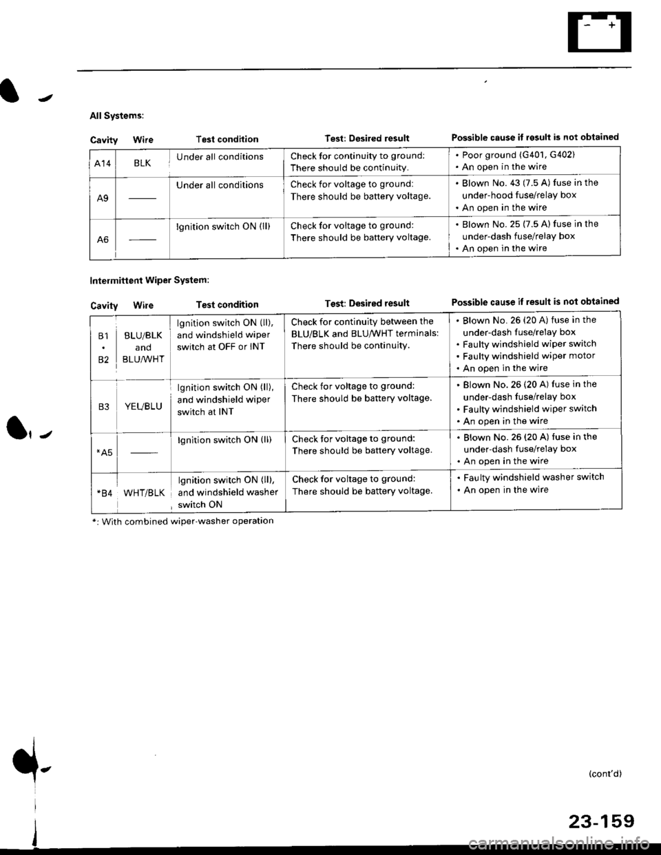
All Systems:
Cavity Wire
Cavity Wire
Intelmittent Wiper System:
Test condilion
Test condition
Test: Desired resultPossible cause il rgsull is not obtained
Test: Desired resultPossible cause if result is not obtained
Al4BLKUnder all conditionsCheck for continuity to ground:
There should be continuity.
. Poor ground (G401, G402). An open in the wire
A9
Under all conditionsCheck for voltage to ground:
There should be battery voltage.
. Blown No. 43 (7.5 A) fuse in the
under-hood fuse/relay box
. An open in the wire
A6
lgnition switch ON (ll)Check for voltage to ground:
There should be baftery voltage.
. Blown No. 25 (7.5 A) fuse in the
under-dash fuse/relay box. An open in the wire
B1
82
BLU/BLK
and
BLU,^/VHT
lgnition switch ON (ll),
and windshield wiper
switch at OFF or INT
Check for continuity between the
BLU/BLK and BLU/WHT terminals:
There should be continujty.
Blown No. 26 {20 A) fuse in the
under-dash fuse/relay box
Faulty windshield wiper switch
Faulty windshield wiper motor
An open in the wire
B3YEUBLU
lgnition switch ON (ll),
and windshield wiper
switch at INT
Check for voltage to ground:
There should be battery voltage.
Blown No.26 (20 A) fuse in the
under-dash fuse/relay box
Faulty windshield wiper switch
An open in the wire
*A5lgnition switch ON (ll)Check tor voltage to ground:
There should be battery voltage.
. Blown No.26 (20 A) fuse in the
under-dash fuse/relay box. An open in the wire
WHT/BLK
lgnition switch ON { ll),
and windshield washer
switch ON
Check for voltage to ground:
There should be battery voltage.
. Faulty windshield washer switch
. An open in the wire
*: With combined wiper'washer operatlon
{-(cont'd)
Page 1684 of 2189
Wipers/Washers
Component Location Index
SBS components are located in this area, Review the SRS component locations, precautions, and procedures in the SRSsection (241 betore performing repairs or service.
WIPER/WASHER SWITCHTest, page 23-215REAR WINDOW WIPERMOTOR lHatchback)Test, page 23'216WINDSHIELD WIPER ARMS/BLADES
WINDSHIELD WIPER MOTORTest, page 23-215
WASHER FLUIDRESERVOIR
WASHER MOTOR {Hatchback)Test, page 23'216
INTERMITTENT WIPER RELAYCIRCUIT (ln the integratedcontrol unit)
t_l
Iilr
i
T
23-214
Page 1685 of 2189
IJCircuit Diagram (Windshield)
UNDER DAS'IFUSE F'-AY B3X
GRN Bt(
a/
BLK
G40lG402
8LK
G401G402
.r^_",,,*:
{ M } WASHEF
Y
r,roroR
IBLK
I
I
I-
GzO2
COMB NED OPERAT ON WIPEF/WASHER
UNDER,HOOD FUSElFELAY BOX
o ooo?, I t Y",i
NTEGRATEDCONTROLIINIT
/ Has b! ll.Ln \1 nlernrltent I w per reray l
WLNDSHIELD W PEF MOTOR
23-215
l-'
Page 1687 of 2189

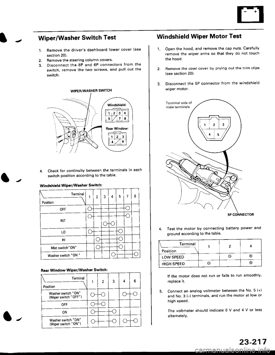
Wiper/Washer Switch Test
Remove the driver's dashboard lower cover {see
section 20).
Remove the steering column covers.
Disconnect the 8P and 6P connectors from the
switch, remove the two screws, and pull out the
switch.
4. Check tor continuity between the terminals in each
switch position according to the table
Windshield Wiper/Washer Switch:
Terminal
Position \
12357I
OFFoo
INTo-o
oo
LOoo
HIoo
l\4ist switch"0N"oo
Washer switch "0N "oo
Rear Window WiPer/Washer Switch:
I Terminal
'i"*
--J2346
Washer switch "0N"
(Wiper switch "OFF"lo--oo--o
OFFo--o
ONo--o
Washer switch "0N"
{Wiper switch "0N")o--oo--o
1.
WIPER/WASHER SWITCH
Windshield:
l1 2 314 |
li.l7a,lil
Rear Window:
11 z 3l
lT-,rtl
Windshield Wiper Motor Test
1.Open the hood, and remove the cap nuts. Carefully
remove the wiper arms so that they do not touch
the hood.
Remove the cowl cover by prying out the trim clips
(see section 20).
Disconnect the 5P connector lrom the windshield
wiper motor.
Test the motor by connecting battery power
ground according to the table.
lf the motor does not run or fails to run smoothiy,
replace it.
5. Connect an analog voltmeter between the No. 5 {+)
and No.3 {-) terminals. and run the motor at low or
high speed.
The voltmeter should indicate 0 V and 4 V or less
alternately.
Terminal
i**l*-
-_\14
LOW SPEEDo@
HIGH SPEEDo@
23-217
Page 1824 of 2189

Connector Views
To see the configuration of a connector's cavities, look up its view number in the Connector
View section in the back of the book. Each view includes the color of the connector, where it
is located, and what it connects to.
Use the Connector Views to help locate the proper cavity when you need to probe a
connector. lt can be especially helpful if the connector has more than one wire of the same
cotor.
Connector views can also be used to help diagnose multiple symptoms in separate circuits
which could be caused by a single problem in a connector shared by those circuits. Here's
how:
1. Pick one of the multiple symptoms and look up the schematic for that circuit.
2. Make a list of all the in-line and fuse box connectors in that schematic (include page
numbers).
3. Then, in the Connector View section, look up each connector on your list to see il circuits
related to the other symptoms run through one of them. lf they do, inspect that connector
for the oroblem.
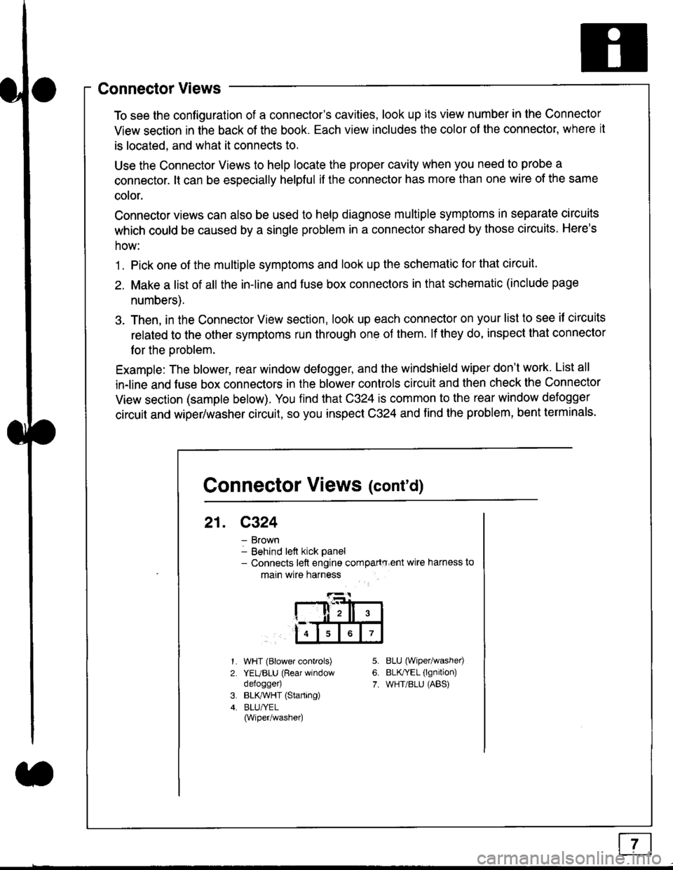
Example: The blower, rear window defogger, and the windshield wiper don't work. List all
in-line and fuse box connectors in the blower controls circuit and then check the Connector
View section (sample below). You find that C324 is common to the rear window defogger
circuit and wiper/washer circuit, so you inspect C324 and find the problem, bent terminals.
5.
6.
7.
1.
2.
WHT (Blower controls)
YEUBLU (Rear window
defogger)
BLK,ryVHT (Starting)
BLU/YEL(Wiper/washe0
8LU (Wiper/washed
BLfiEL (lgnition)
WHT/BLU (ABS)
Connector Views (cont'd)
21. C324
Brown
Behind left kick panel- Connects left engine compartry'ent wire harness to
main wire harness
ll,ll,
567
Page 1840 of 2189

Ground-to-Components I ndex
f.,lONOTE: All ground wires are BLK unless otherwise noted.
GroundPageComponents or Circuit Grounded
Battery (BLKYEL)
Steering pump bracket
t+-rg ITransmission housing
l
G101
(-1)
G101
(-2)
14-2
and
14-3
ano
14-1
Powertrain or engine control module (PG1 and pG2 are BLK: LG1 and LG2 are
BRN/BLK), EGR control solenoid valve (CW, EGR valve and lift sensor (Dt6yS enginewith M,/T), Engine coolant temperature switch, pGM-Fl main relay, power steeringpressure switch (USA), Primary HO2S (D16Y5 engine with l\/,/T), Vehicle speed sensor,VTEC pressure switch (D16Y5/D16Y8 engines), CKF sensor (BRN/BLK), Transmission
control module (CYf) (Pc1 is BLK: LG1 is BRN/BLK)
Shielding betvveen the PCM or ECM and these components (all have BRN/BLK wires):
CKF sensor, TDC/CKP/CYP sensor. Primary and secondary heated oxygen sensors.
Knock sensor (CWDl6YB engine), Mainshaft speed sensor (AiT except CVT),
I Countershaft speed sensor (A/T except CVf)
Shielding between the TCM and these components (CVT) (all have BRN/BLK wires):
Drive pulley speed sensor, Driven pulley speed sensor, Secondary gear shaft
speed sensor
Powertrain or engine control module (PG1 and pG2 are BLK; LG1 and LGz are
BRN/BLK), EGR control solenoid valve (D16Y5 engine), EGR valve (Dt685), Engine
coolant temperature switch, Fuel pressure regulator shut-off solenoid valve (D1685),
PGM-FI main relay, Power steering pressure switch (USA), Vehicle speed sensor, VTECpressure switch (All except D16Y7 engine), CKF sensor (A
except 81642) (BRN/BLK)
Shielding between the PCM or ECM and these components (all have BRN/BLK wires):
CKF sensor, TDC/CKP/CYP sensor, Primary and secondary heated oxygen sensors,
Knock sensor (All except D16Y7 engine), i/ainshaft speed sensor (Arf except CW),
Countershaft speed sensor (A,/T except CVf), Drive pulley speed sensor (CW), Drivenpulley speed sensor (CVT), Secondary gear shaft speed sensor (CVf)
I Badiator fan motor, Right front parking/turn signat tight, Right headtight
G20214-4I Cruise control actuator, Left front parking/turn signal lights, Left headlight, Rear window
I washer motor, Windshield washer motor, Washer fluid level switch (,99-'00 Canada)
G401| +-o
and
14-7
Accessory power socket, Brake fluid level switch, Clutch interlock switch (M/T), Clutchswitch (lillT with cruise/D16Y5 engine with MfD, Combination wiper switch (Z wires),
Cruise control main switch, Cruise control unit, Dash lights brightness controller, Data
link connector, Daytime running lights control unit (Canada), Gauge assembly, Horn('96-'97 models), Integrated control unit, Interlock control unit (ArI), Keyless door lock
control unit ('99-'00 models with keyless), Moonroof close and open relays, Moonroof
switch, Park pin switch (A/r), Power window relay, Rear window defogger relay, Rear
window defogger switch ('96-'98 models), Steering lock, Stereo radio tuner (,96-,98
USA: LX, EX, and HX), Turn signal/hazard relay, Windshield wiper motor.....plus
everything grounded through G402
6-6
Page 1849 of 2189
cs01 c928l.l!9!9-e ofi|oNCONNECTORPHO|O 62
'99.'00
modals
A42A
tl
tl
AUDIOUNITPage 150
COMBINATIONACCESSORYPOWERSOCKET
tl
tl
STEREORAOIOTUNERPage 150
vlEw 6a
WIPERswtTcHPage 91
vlEv\/ 65
WINDSHIELDWIPERMOTOR
(cont'd)
10-7
Page 1985 of 2189
-----1
,.l
IF3---------
wEw 5a
"{
tai BTA
ttlir'I l� lntdmiitant/ha.k
ot r s€e cround ou r coMBrN\ill?H
I 3l'#ltgl I '"Y;Isil
",.u,".*l I
*-l -'tEt165
! l----l aLU'wH
r '"""""--:--
|
: F#1.,--.J---- ---------;
,r___f ______ -__?F___?_rt |NTE_
| / Intermittenvoark H.t rs"'ti- | i $$p f wioer contrcitr \""- --"-' tr'Psr
l litrlY, | cround ll1a
J ! J. Inlerminanl wipsr Rolay Circuit i
, r 1ao6Ttn
t ( |lizlff,ll;'- ffiI 'n"*-li3$H'o'
4
GFN/ELK
4
WINDSHIELDWIPER MOTOR
r---':G-'---r: c4olPHOTO 57
WlndshlrldWipor/WarharSwltch
---------J
B2
A51INTE.
-".ir--;;;;
.i.5^t Distribution,
"i]5
Park lgnitionInput
oFF ( Inr Lo, tll-a- -4. I
UNDER-DASHFUSE/RELAYBOXPHOTO 58
91-1