1999 HONDA CIVIC idle pulley
[x] Cancel search: idle pulleyPage 62 of 2189

Unit of length: mm lin)
STANDARD {NEW) SERVICE LIMITMEASUREMENT
Differential
Dtri"*"t"|p'.b"gear
S"t rrg-t" b""il"s
Pinion shaft contact area LD.
Carrier-to pinion clearanceDrive shaft contact area l.D.Carrier to driveshaft clearance
BacklashLD.Pinion gear to-pinion shafl clearance
)uter race clearance
18.010 18.028'0.7091 - 0.7098)
0.023 0.057 (0.0009 - 0.0022) 0.1 (0 004)
26.025 - 26.045 (.0246 1 0254\0.045 0.086 (0.0018 - 0.0034) 0.12(0.005)
0 05 - 0.15 i0 002 0.006)18 042 18.066 {0.7103 0.7" l3)
0.055 - 0.095 (0.0022 - 0.0037) 0.15 {0.006)
0 0.15 (0 - 0.006) Adjlrst
MEASUBEMENT Wire DiaO.D. Free Length I No. of Coils
SpringsPH regulator valve spring 1 2 (0 047)
PH control valve spring 1 7 {0.067)PL regulator valve spring 0 9 (0.035)
PH'PL control valve spring 1 0 (0 039)
crutlh reduc'ns vdrve spnns ] :19 9]:lLLbrication valve spring I b (u ubJr
Shitt valve spring 1 4 (0.055)
Shift control valve spring 1 0 (0.039)
Stan clutch control valve spring 0.4 (0 016)
Pitot regulator valve spring 0.6 (0 024)
Start clutch valve accumulator spring 1 2 \0 O47)
Reverse control valve spring 1 2 (0.047)
Shift inhibitor valve spring 1 3 (0 051)
9.0 {0.354)13.4 (0.528)
1.2lO.2A3\10.0 (0.394)
16.8 (0.661)
13.4 (0.528)
8.2 (0.323)
1 .4 t0.29114.1 (0.161)
5.7 t0.224)8.3 {0.327)9.4 (0.370)
13.2 (0.520)
26.7 (1.051)
39.4 (1.551)
14.6 (0.575)
31.4 (1.236)
44.4 \1.14al51.6 (2.031)
34.1 (1.343)
19.3 (0.760)
12.1 (0.476)
9.5 (0.374)
29.8 (1.173)
31.4 (1.236)
48.3 (1.902)
r0.08.11.28.68.0
13.01.56.85.012.311.010.6
Section 14
SteeringSection 17
M/S: [,4anual steering, P/Sl Power steering*: When using a ne; bett, adjust dellection or tension to new values. Run the engine for 5 minutes then turn it off-
Readjust the deflection or tension to used belt values.
cw
MEASUREMENTSTANDARD {NEWI
Steering wheelPlay at steering wheel circumferenceStarting load at steering wheelcircumferenceN (ksf, lbf)Manual steeringPower steering Engine running
0 - 10 (0 0.4)
15 (1.5,3.3)
29 (3.0,6.6)
GearboxAngle of rack guide screw loosened M/S
from locked position P/S
Preload at pinion gear shaft N m (kglcm, lbfin) M/S
20!5"20'Max0.5 - 1.7 (5 - 17,4.3 - 14.8i
0.6 1.2 (6 - 12, 5.20 - 10.42)
Pump pressure with valve closed(oil temp./speed: 40'C (105"F) min./idleDo not run for more than 5 seconds).kPa (kgtcm?, psi)
6,400 - 7,400 {65 - 75, 920 - 1,070)
Power steeringfluidRecommended power steering fluid
Fluid capacity | {US qt, lmp q0Reservoir
HONDA Power Steering Fluid
0.85 (0.90,0.75) at disassembly0.4 {0.42.0.35}
7.5 11.0 {0.30 - 0.43)with used belt
5.0 7.0 (0.20 0.28) with new belt10.5 - 14.0 10.41 - 0.55) with used belt7.5 10.010.30 0.39) with new belt
390 540 {40 55,88 '120) wrth used bek
340 - 490 (35 - 50, 77 - 110) with used belt
740 880 (75 - 90, 170 - 200) with new belt
640 780 (65 - 80, 143-176)with newbelt
Power steeringbelt*
Deflection with 98 N (10 kgf,22 lbf)
between pulleys '99 modell 81642 Engine Type only
'96 '99 models: Other Engine TYPes
ron.ionffiN (kgf, lbf) '99 model: 81642 Engine Tvpe only'96 -'99 models: Other Engine TYPes'99 modelr 81642 Engine TYPe onlY'96 '99 models: Other Engine TYPes
3-17
Page 64 of 2189

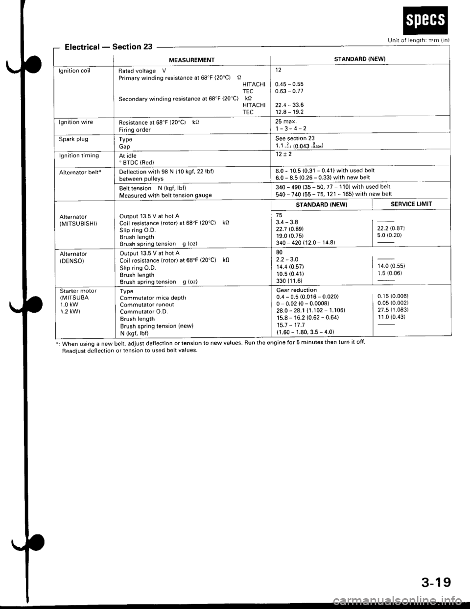
ElectricalSection 23
*: When using a new belt, adjust deflection or tension to new values. Run the engine for 5 minutes then turn it off
Readiust deflection or tension to used belt values
Unit of englh: mm {n)
MEASUREMENTSTANDARD {NEW}
lgnition coilRated voltage VPrimary winding resistance at 68'F (20'C) oHITACHITEC
Secondary winding resastance at 68'F 120"C) kOHITACHITEC
12
0.45 0.550.63 0.11
22.4 - 33.612.A - 19.2
lgnition wireResistance at 68'F (20'C) kf)
Firing order
25 max.1-3-4 2
Spark plugTypeGap
See section 231.1 3, (o.o€ -3*.)
lgnition timingAt idle' BTDC lRed)
Alternator belt+Deflection with 98 N (10 kgf,22lbf)between pulleys8.0 - 10.5 {0.31 - 0.41} with used belt
6.0 - 8.5 {0.26- 0.33)with new belt
Belt tension N (kgf, lbf)
Measured with belt tension gauge340 - 490 (35 - 50, 77 110) with used belt
540 - 740 (55 - 75, 121. 165)whh newbert
(MITSUBISHI)Output l3.5 V at hot ACoal resistance (rotor) at 68'F (20"C) kO
Slip rins O.D.Brush lengthBrush spring tension g (oz)
STANDARD INEWI SERVICE LIMIT
753.4-3.8 I -
Z2.j \0.A9) 22.2 \0.47)19.0 (0.75) 5.0 (0.20)
340 420 (12.0 14.8)
Alternator(DENSOiOutput '13.5 V at hot A
Coil resistance (rotor) at 68'F (20'C) k0
Slip ring O.D.Erush lengthBrush spring tension g (oz)
802.2 - 3.014.4 (0.57) | 14.0 (0.55)
10.5 (0.41) 1.5 (0.06)
330 {11.6)
Starter(MITSUEA
1.0 kw1.2 kW)
TvpeCommutator mica depthCommutator runoutCommutator O.D.Brush lengthBrush spring tension (new)
N (ksf, lbf)
Gear reduction0.4 - 0.5 (0.016 - 0.020) 0.15(0.006)
o o.o2 (o - 0.000e) | o.o5 (o.oo2)
28.0-28.1 (1.102 1.106) | 27.5(1.083)
15.8 - 16.2 10.62 - 0.64) 11.0 (0.43)
15.7 - 11 .1
{1.60 - 1.80, 3.5 - 4.0i
3-19
Page 100 of 2189

Engine Removal/lnstailation
Removal (cont'dl
Dl6Y5. DrGYr, D16Y8 enginas:
-1. Remove the mounting bolt and lock bolt, thenremove the P/S pump belt and pump.
MOUNTING BOLT8 x 1.25 mm24 N.m {2.4 kgl.m, 17 tbf.ftl
LOCK BOLT8 x 1.25 mm24 N.m 12.4 kgf.m, 17 lbf.ftl
17. Loosen the idler pulley center nut and adjustingbolt, then remove the air conditioning (A[/C)compressor belt.
IDI.IR PULLEY CENTERNUT10 x 1.25 mma,l N.m {,1.5 kgt.m, 33 lbf.ft)
5-6
(
'18. Remove the ransmission ground cable and hosect8mo.
HOSE CLAMP6 x '1.0 mm
19. Remove the clutch slave cylinder and line/hoseassembty (M/T).
NOTE:
. Do not disconnectthe pipe/hose assembly.. Do not operate the clutch pedal once the slavecylind€r has been removed.o Take care not to bend the line.
6x1,0mm 8x1.2Smm11 N.m {1.1 kgt.m, 2a N.m t2.4 kgf.m,I tbf.ftl 17 tbf.ftl
8 x 1.25 mm2a N'm {2,4 kgt m,17 tbt.ftl
Page 130 of 2189

Removal
NOTE:
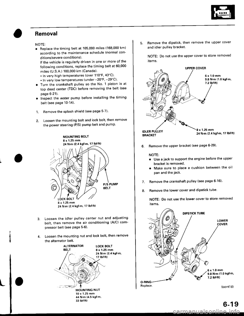
. Replace the timing belt at 105,000 miles (168.000 km)
according to the maintenance schedule (normal con-
ditions/severe conditions).
lf the vehicle is regularly driven in one or more of the
followlng conditions, replace the timing belt at 60.000
miles (U.S.A.) 100,000 km {Canada).
.In very high temperatures (over 110'F.43'C)
. In very low temperatures (under -20'F, -29"C)'
! Turn the crankshaft pulley so the No. 1 piston is at
top dead center (TDC) before removing the belt (see
page 6'21).
. Inspect the water pump before installing the timing
belt {see Page 10-14).
1. Remove the splash shield (see page 5-7).
2. Loosen the mounting bolt and lock bolt. then remove
the power steering (P/S) pump belt and pump
MOUNTING BOLT
8 x 1.25 mm2il N m 12.4 kgl m, 17 lbf'ft)
P/S PUMPBELT
I x 1.25 mm24 N m (2.4 kgf m, 17 lbt ft)
Loosen the idler pulley center nut and adjusting
bolt, then remove the air conditioning (AVC) com-
pressor belt (see Page 5-6).
Loosen the mounting nut and lock bolt, then remove
the alternator belt.
ALTERNATORBELTLOCK BOLTI x 1.25 mm24 N.m 12.4 kgf.m,r? tbI.ft)
3.
MOUNTING NUT10 x 1.25 mm44 N.m 14.5 kgl m,
33 rb{ ft)
5. Remove the dipstick, then remove the upper cover
and idler PulleY bracket
NOTE: Do not use the upper cover to store removed
items.
6x1.0mm9.8 N.m 11.0 kgf.m,7.2
IDLERI x 1.25 mm24 N.m (2.4 kgl.m, 17 lbf'ft)BRACKET
6. Remove the upper bracket {see page 6-29)
NOTE:
. Use a jack to support the engine before the upper
bracket is removed
. Make sure to place a cushion between the oil
pan and the jack.
Remove the crankshaft pulley (see page 6-16).
Remove the lower cover and dipstick tube
NOTE; Do not use the lower cover to store removed
items.
1.
.'.
DIPSTICK TUBE
LOWER
6x1.0mm9.8 N.m (1.0 kgf m,
7.2 rbt.ft)
(cont'd)
6-19
Replace.
Page 133 of 2189

Crankshaft Speed Fluctuation (CKF) Sensor
2.
3.
5.
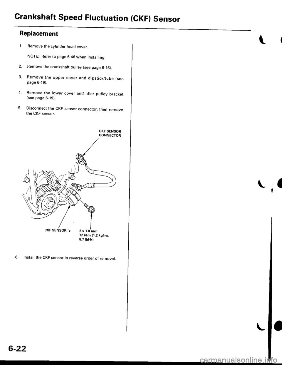
Replacement
4.
1.
6x1.0mm'12 N.m {1.2 kgt.m,8.7 tbf.ft)
6. Installthe CKF sensor in reverse order of removal.
Remove the cylinder head cover.
NOTE: Refer to page 6-46 when installing.
Remove the crankshaft pulley (see page 6_16),
Remove the upper cover and dipstick/tube {seepage 6-19).
Remove the lower cover and idler pulley bracket(see page 6-19).
Disconnect the CKF sensor connector, then removethe CKF sensor.
CKF SENSORCONNECTOR
6-22
:(
I
Page 138 of 2189

Removal
Engine removal is not required for this procedure
!!!s@ Make sure iacks and salety stands are
f ta"eata"ea propetty and hoist brackets are attached to the
correct positions on the engine.
CAUTION:
. Use tender covels to avoid damaging painted sul-
faces.
o To avoid damage, unplug the wiling connectors
carefully while holding the connector portion to
avoid damage.
. To avoid damaging the cylinder head, wait until the
engine coolant temperature drops below 100"F
{38"C} before loossning the tetaining bolts.
NOTE:
o Mark all wiring and hoses to avoid misconnectlon
Also, be sure that they do not contact other wiring or
hoses, or interfere with other parts.
. Inspect the timing belt before removing the cylinder
h ead.
. Turnthe crankshaft pu lley so that the No. lpistonisat
top dead center (see Page 6-21)
'1. Disconnect the negative terminal from the battery'
Drain the engine coolant (see page'10-7).
a Remove the radiator cap to speed draining.
Remove the intake air duct and air cleaner housing
(see page 5 3).
Remove the mounting bolt and lock bolt. then
remove the power steering (P/S) pump belt and
pump (see page 5'5).
Loosen the idler pulley center nut and adjusting
bolt' then remove the air conditioning (A'lc) com-
pressor belt (see Page 5-6).
Loosen the mounting nut and lock bolt. then
remove the alternator belt (see page 6-19).
Remove the P/S pump bracket (see page 5-12).
3.
4.
2.
6.
1.
8. Remove the throttle cable by loosening the locknut,
then slip the cable end out of the throttle linkage
NOTE:
. Take care not to bend the cable when removing it
Always replace any kinked cable with a new one
. Adjust the throttle cable when installing (see sec-
tion 1 1).
D16Y7 engine:
Dl6Y5, Dl6Y8 engines:
THFOTTLECABLE
(cont'd)
6-27
LOCKNUT
CABLE
Page 172 of 2189

Timing Belt
Removal
NOTE:
. Replace the timing belt at 105,000 mites (168,000 km)according to the maintenance schedule (normal con-ditions/severe conditions).
lf the vehicle is regularly driven in one or more of thefollowing conditions, replace the timing belt at 60,OOOmiles (U.S.A.) 100,000 km {Canada).. In very high temperatures (over 110"F, 43"C).. In very low temperatures (under -20.F, 29.C).. Turn the crankshaft pulley so the No. 1 piston is attop dead center (TDC) before removing the belt (seepage 6-57).
. Inspect the water pump before installing the timingbelt {see page 10-14).
1.
IOLER PULLEY BRACKETEOLT10 x 1.25 mm44 N.m 14.5 kgf.m, 33 bnft)
6-62
Remove the splash shield (see page 5-9).
Remove the adjusting bolt and mounting bolts, thenremove the power steering (P/S) pump belt andpump.
8xL25mm24 N m {2.{ kgf.m, 17 lbf.ft)
Loosen the idler pulley bracket bolt and adjusting bolt,then remove the air conditioning (A,/C) compressorbelt aDJUsnNG
44 N.m 14.5 kgt.m, 33 lbf.ft)
P/S PUMP LOWER ARACKET
a\
4. Loosen the mounting nut and lock bolt, then removethe alternator belt.
LOCK BOLT8 x 1.25 mm24 N.m {2.4 kgt.m.17 rb{.ftl
5. Remove the upper bracket (see page 6-69).
NOTE:
. Use a jack to support the engine before removingthe upper bracket.
o Place a cushion between the oil pan and the jack.
Remove the P/S pump lower bracket
8 x 1.25 mm24 N.m 12.,1 kgf.m,17 tbf.ftl
l0 x 1.25 mm
'-f'
MOUNTING10 x 1.25 mm44 N.m (4.5 kgf.m.33 rbf.fttBELT
HEAT SHIELD
Page 177 of 2189

Removal
Engine removal is not required for this procedure.
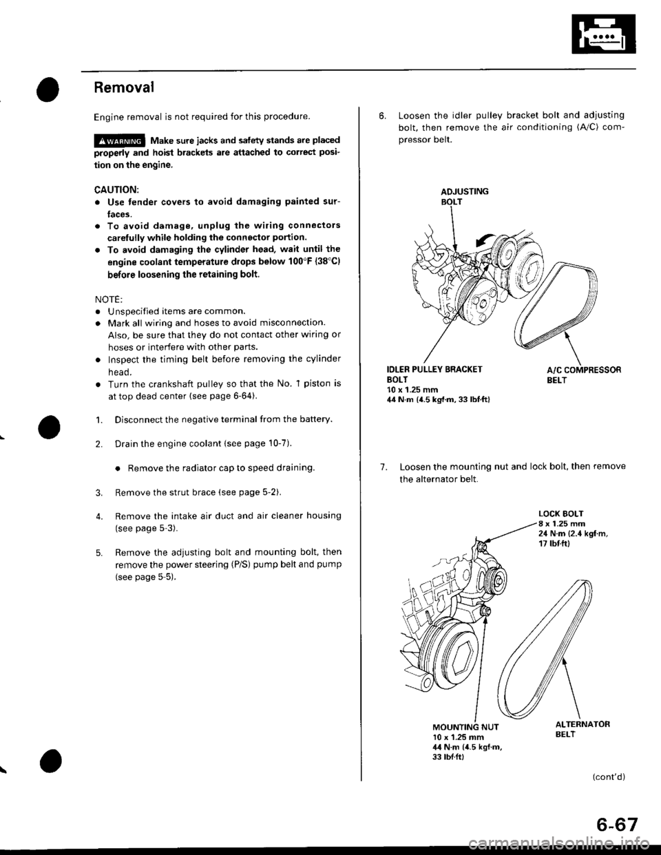
!@@ Make sure jacks and safety stands are placed
properly and hoist brackels are attached to correst posi-
tion on the engine,
CAUTION:
o Use fender covers to avoid damaging painted sur-
faces.
To avoid damage, unplug the wiling connectors
carelully while holding the connector portion.
To avoid damaging the cylinder head, wait until the
engine coolant temperature drops below 100"F {38'Cl
before loosening the retaining bolt.
NOTE:
. Unspecified items are common.
. Mark all wiring and hoses to avoid misconnection.
AIso, be sure that they do not contact other wiring or
hoses or interfere with other parts.
o Inspect the timing belt before removing the cylinder
n eao.
. Turn the crankshaft pulley so that the No. 1 piston is
at top dead center (see page 6-64).
1. Disconnect the negative terminal from the battery.
Drain the engine coolant {see page 10-7).
. Remove the radiator cap to speed draining.
Remove the strut brace (see page 5-2).
Remove the intake air duct and air cleaner housing
(see page 5-3).
Remove the adjusting bolt and mounting bolt, then
remove the power steering (P/S) pump belt and pump
(see page 5 5).
2.
3.
4.
\
ADJUSTING
6. Loosen the idler pulley bracket bolt and adjusting
bolt, then remove the air conditioning (A/C) com-
pressor belt.
IDLER PULLEY BRACKETBOLT10 x 1.25 mm44 N.m {4.5 kg,l.m, 33 lbt.ft}
7. Loosen the mounting nut and lock bolt, then remove
the alternator belt.
LOCK BOLT8 x 1.25 mm24 N.m {2.4 kgf.m,17 tbtftl
ALTERNATORBELT10 x 1.25 mm,l,l N.m {4.5 kgf.m,33 tbf.ft,
(cont'd)
6-67