Page 1810 of 2189
Gable Reel
Replacement
!@@ store a .emove airbag assambly with thepad surtace up. lf the airbag is improperly stored face
down, accidental deploymont could propel the unit withenough force to cause sorious iniury.
CAUTION:
. Alwsys disconnect the airbag connoctor(s) when ih€harness is disconngcted.
. Do not disassemble or tamper with the airbag.
NOTE: Carefully inspect the airbag assembly beforeinstalling it. Do not install an airbag that shows signs ofbeing dropped or improperly handled. such as dents,cracks or deformation.
l.Disconnect the battery negative cable. then discon-nect the positive cable from the battery, and wait atleast three minutes.
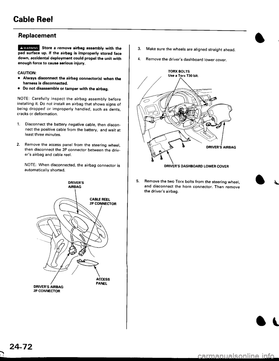
Remove the access panel from the steering wheel,then disconnect the 2P connector between the driv-er's airbag and cable reel.
NOTE: When disconnected, the airbag connector isautomatically shorted.
DRIVER'SAIRBAG
)
24-72
or
TORX EOLTSUse a Torx T30 bit.
DRIVEB'S DASHBOARD LOWER COVER
4.
Make sure the wheels are aligned straight ahead.
Remove the driver's dashboard lower cover.
5. Remove the two Torx bolts from the steering wheel,and disconnect the horn connector. Then removethe driver's airbag.
\
Page 1813 of 2189
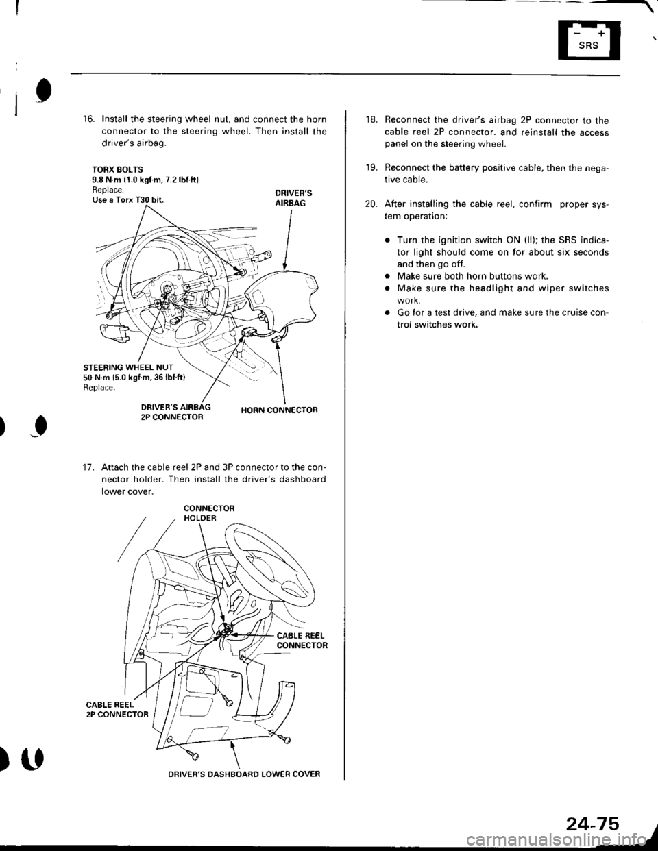
16. Install the steering wheel nut, and connect the horn
connector to the steering wheel. Then install the
driver's airbag.
TORX SOLTS9.8 N m 11.0 kgf m, 7.2 lbtftlReplace.Use a Torx T30 bit.
STEERING WHEEL NUT50 N.m 15.0 kgf.m,36lblft)Replace.
DRIVEB'SAIRBAG
DRIVER'S2P CONNECTOBHORN CONNECTOB
I
17.Attach the cable reel 2P and 3P connector to the con-
nector holder. Then install the driver's dashboard
lower cover.
)UDRIVER'S DASHBOARD LOWER COVER
24-75
18. Reconnect the driver's airbag 2P connector to the
cable reel 2P connector. and reinstall the accesspanel on the steering wheel.
19. Reconnect the battery positive cable, then the nega-
tive cable.
20. After installing the cable reel, confirm proper sys-
tem operation:
Turn the ignition switch ON (ll); the SRS indica-
tor light should come on for about six seconds
and then go off.
Make sure both horn buttons work.
Make sure the headlight and wiper switches
Go for a test drive, and make sure the cruise con
trol switches work.
a
a
Page 1814 of 2189
SRS Unit
Replacement
CAUTION:
. Betore disconnoqting lny pErt of the SRS wire hal-ness, disconnect th9 airbag conn"ctorlsl.. During installltion or teplacemsnt. do not bump(impact w.cnch, hamm€r stc.l the area noar tho SRSunit.
NOTE:
o Do not damage the SRS unit terminals or connectors.. Do not disassemble the SRS unit; it has no service-able parts,
. Store the SRS unit in a clean, dry a.ea,. Do not use any SRS unit which has be€n subjected towater or shows signs of being dropped or improperlyhandled. such 8s dents, cracks or deformation.
1. Disconnect the bsttery negative cable. then discon-nect the positive cable from the battery, and wait atleast three minutes.
2. Disconnect the airbag connector{s}:
NOTE: When disconnected, the airbag connector isautomatically shorted,
Driver's Side:
. Remove the access panel from the steering wheel.then disconnect the 2P connector between the driv_er's airbag and cable reel (see page 24-11).
Front Passenge/s Side:. Disconnect the 2P connector between the tront oas_senger's airbag and SRS main harness (see page 24-11).
24-76
o\
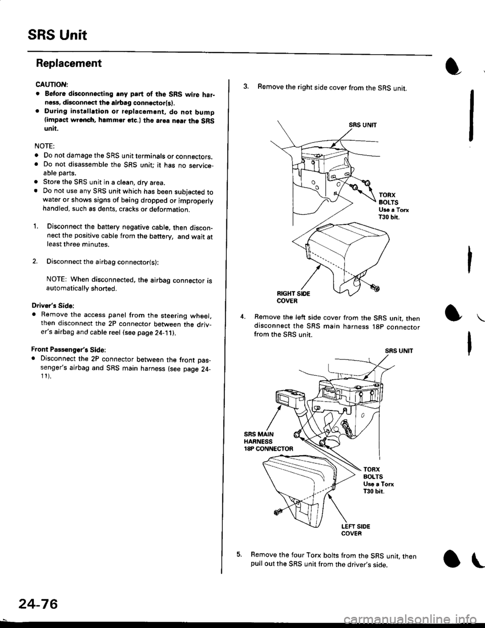
3. Remove the right side cover from the SRS unit.
SRS UNTT
TOBXBOLTSUge a TorxT30 bit.
RIGHT SIOE
Remove the left side cover from the SRS unit, thendisconnect the SRS main harness lgp connectorfrom the SBS unit.
SRS UNIT
5. Remove the four Torx bolts from the SRS unit, thenpull out the SRS unit from the driver,s side,
COVER
Page 1815 of 2189
6. Install the new SRS unit.
NOTE: Do not reuse a torx bolt that has red
threads. Replace the bolt with a new one.
)
7.
TORX BOLTS9.8 N.m l'1.0 kg{.m, 7.2 lbf.ft}Use a Torx T30 bit.
Connect the SRS main harness l8P connector to the
SRS uniu push it into posjtion until it clicks.
Install the SRS unit covers (ri9ht and left). Make
sure the covers snap together in the middle.
8.
TORX BOLTS9.8 N.m 11.0 kgf.m, 7.2 lbf.ft)U3e . Torx T30 bit.
SRS MAIN HARNESS
)(l
9.
10.
't2.
Reconnect the driver's aibag 2P connector to the
cable reel 2P connector, then reinstall the access
panel on the steering wheel.
Reconnect the tront passenger's airbag connector
to the SRS main harness.
Reconnect the battery positive cable, then the nega
tive cable.
After installing the SRS unit, confirm proper system
operation: Turn the ignition switch ON (ll); the SRS
indicator light should come on for about six seconds
and then go oif.
11.
24-77
.-
Page 1824 of 2189
Connector Views
To see the configuration of a connector's cavities, look up its view number in the Connector
View section in the back of the book. Each view includes the color of the connector, where it
is located, and what it connects to.
Use the Connector Views to help locate the proper cavity when you need to probe a
connector. lt can be especially helpful if the connector has more than one wire of the same
cotor.
Connector views can also be used to help diagnose multiple symptoms in separate circuits
which could be caused by a single problem in a connector shared by those circuits. Here's
how:
1. Pick one of the multiple symptoms and look up the schematic for that circuit.
2. Make a list of all the in-line and fuse box connectors in that schematic (include page
numbers).
3. Then, in the Connector View section, look up each connector on your list to see il circuits
related to the other symptoms run through one of them. lf they do, inspect that connector
for the oroblem.
Example: The blower, rear window defogger, and the windshield wiper don't work. List all
in-line and fuse box connectors in the blower controls circuit and then check the Connector
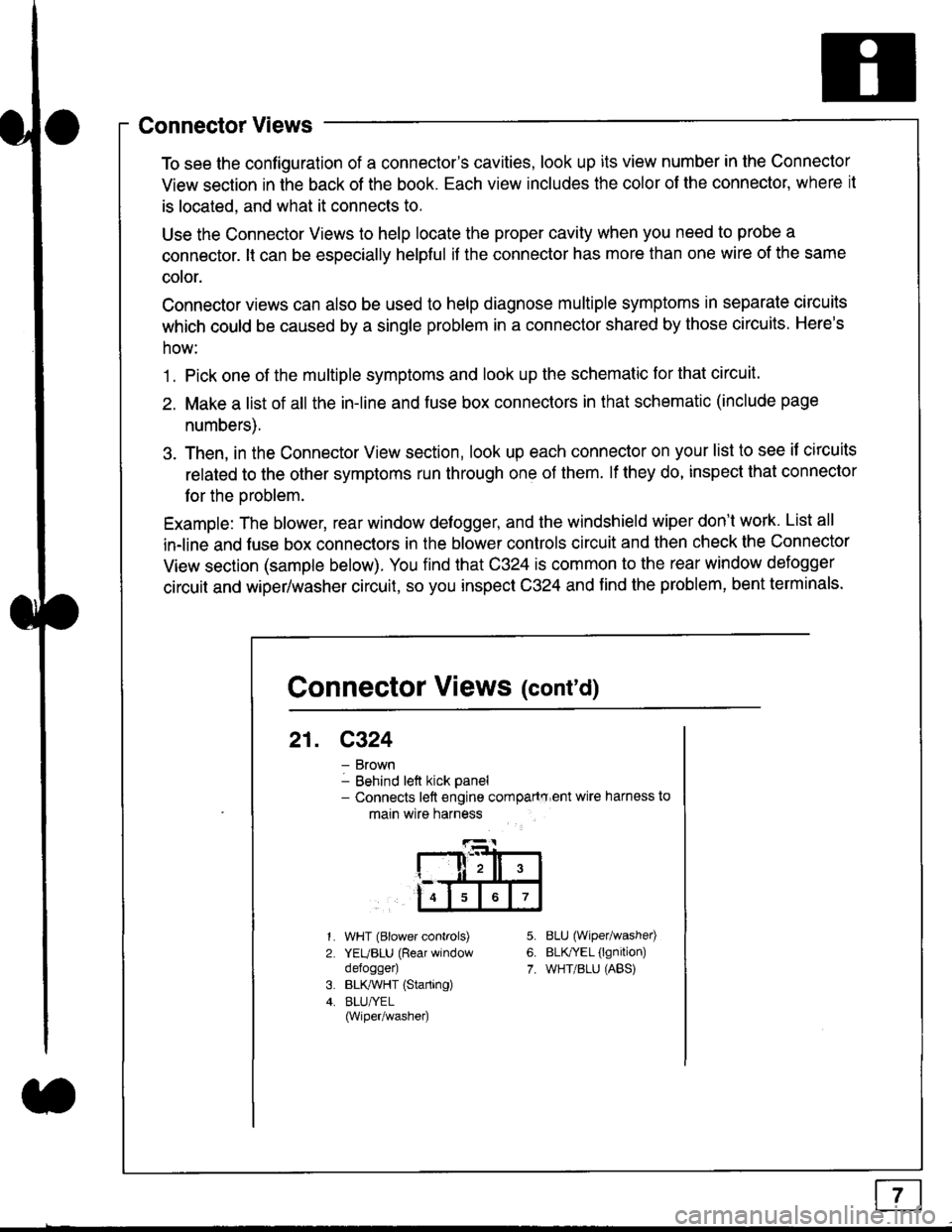
View section (sample below). You find that C324 is common to the rear window defogger
circuit and wiper/washer circuit, so you inspect C324 and find the problem, bent terminals.
5.
6.
7.
1.
2.
WHT (Blower controls)
YEUBLU (Rear window
defogger)
BLK,ryVHT (Starting)
BLU/YEL(Wiper/washe0
8LU (Wiper/washed
BLfiEL (lgnition)
WHT/BLU (ABS)
Connector Views (cont'd)
21. C324
Brown
Behind left kick panel- Connects left engine compartry'ent wire harness to
main wire harness
ll,ll,
567
Page 1839 of 2189
Fuse
NumberFuse NameAmpsPage
BATTERY
Component or Circult Protected
Power distribution
lgnition switch
INTERIOR LIGHT | 7.5 | 10-10 | DLC, Ceiling light, Trunk light
FI E/M15 i(20 GX) i
i PGM-FI main relay, Fuel injection relay (GX)
Not used
POWER WINDOW| 10-10 | Power window relay
BACK UPStereo radio iuner ('9G'98 mod€ls), Audio unit ('99100
models), Heater control panel, PCM/ECM, TCM (9e'98
cvr)
HEADLIGHT
REAR DEFROSTER I
DOOR LOCK UNIT,
ROOF
i 10-12i Headlights
Not used
Rear window defogger relay
Power door lock control unit (all except '99-'00 models
with keyless), Keyless door lock control unit ('99-'00
models with keyless), Moonroof
i HORN, SrOP Lri 10-13i Horn relay, Brake switch
HAZARDHazard warning switch
OPTIONI 10-13I Security system (option)
i HEATER MOTOR Ii 10-1 i Blower motor relay
(CONDENSER FAN)
COOLING FANl1o-1
Condenser Jan relay, A'lC compressor clutch relay
Radiator tan relay
&5
Page 1841 of 2189
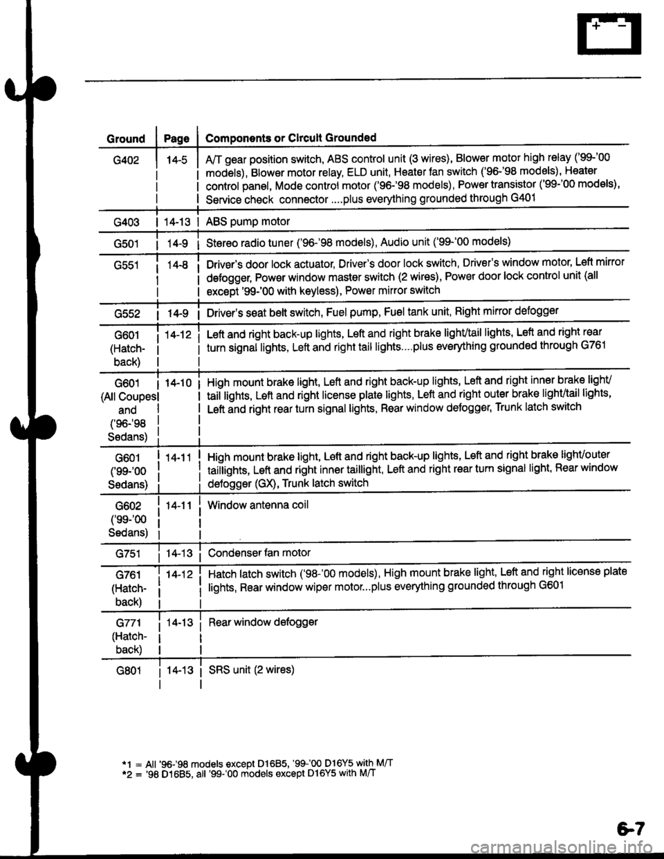
Ground
G402
Components or Clrcult Grounded
Arr gear position switch, ABS control unit (3 wires), Blower motor high relay ('99-'00
models), Blower motor relay, ELD unit, Heater Jan switch ('96-'98 models), Heater
control panel, Mode control motor ('96.�98 models), Power transistor ('99-'00 models),
Service check connector....plus everything grounded through G401
| 14-13 | ABS pump motor
1l-9 i Stereo radio tuner ('96-'98 models), Audio unit ('99-'00 models)
Drivsr's door lock actuator, Driver's door lock switch, Drivefs window motor' Left mirror
defogger, Pow€r window master switch (2 wires), Power door lock control unit (all
except '99-'00 with keyless), Power mirror switch
G55214-9 i Driver's s€at belt switch, Fuel pump, Fuel tank unit, Right mkror defogger
G601
(Hatch-
back)
14-12 iLeft and right back-up lights, Left and right brake lighvtail lights, Lefl and right rear
turn signal lights, Left and right tail lights....plus eveMhing grounded through G761
G601 I 14-10
(All Coupesl
ano
(96198
S6dans)
High mount brake light, Left and right back-up lights, Left and right inner brake lighv
taiilights, Lett and right license plale lights, Lett and right outer brak€ lighvtail lights'
Left and right rear turn signal lights, Rear window deJogger, Trunk latch switch
G601
(99-'oo
Sedans)
G602
('ss-'00
Sedans)
G761
(Hatch-
back)
G771
(Hatch-
back)
14-11
14-12 i
High mount brake light, Left and right back-up lights, Left and right brake lighvouter
taillights, Left and right inner taillight, Left and right rear turn signal light' Rear window
deJogger (GX), Trunk latch switch
Window antenna coil
Hatch latch switch ('98-'00 models), High mount brake light' Left and right license plate
lights, Rear window wiper motor...plus everything grounded through G601
Rear window defogger
14-13 i SRS unit (2 wires)
*1 = All '96-98 models €xcept Dl685, '99100 D16Y5 with M/T*2 = '98 D1685, all '99-'00 models except Dl6Y5 with M/T
e7
Page 1851 of 2189
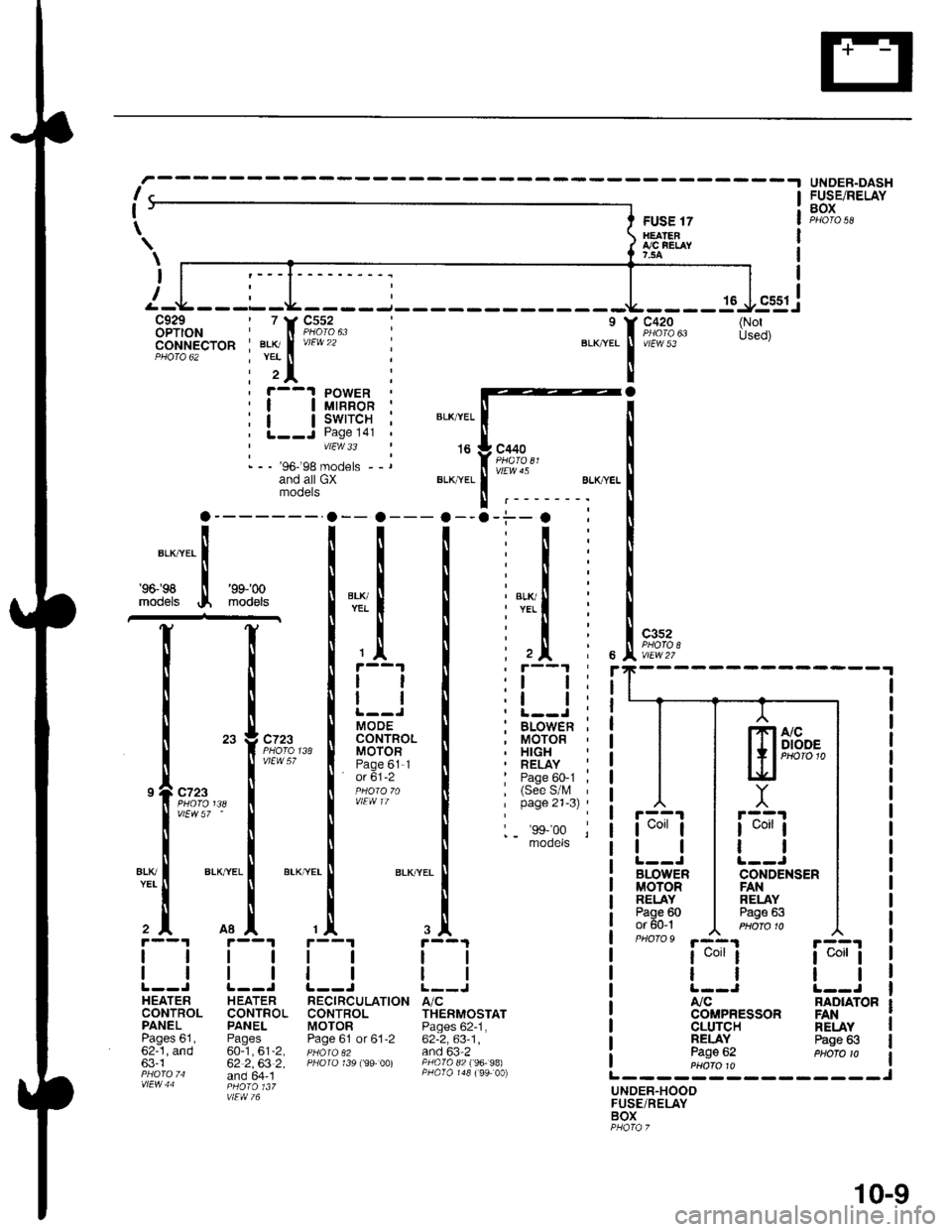
I
I
-- a---
i
i
T
iTl Ill
Irl
ll
tl
MOOECONTROLMOTORPage 61-1' o( 61-2
a
r--1 PowER| | utnnon ;| | swrrcH ;L--J Page l4l 'vtEw 33
- - - '96-'98 models --rand all GXmooers
FUSE 17H€ATENI,/C FEI,AY7,5A
16
c420
vtEw 53
c3s2
r::'l
I uorr I
tl
BLOWERMOTORRELAYPage 60or 60-1PHO|O9 '.a-4.1
I uorr I
tl
A,/C
CLUTCHNELAYPage 62
UNOER-DASHFUSE/RELAYBOX
ia;ij
tl
NAD|ATOR
\
\
I
(NotUsed)
BLK,YEL
't6
BLI(YEL
c440
vlEw 45
BLK/ryEL
'96198
models
'9$'00
mod€ls
I
c?23
vtEw 57 '
ALKTYEL
c723
vlEW 57
atK
2^
1l
ll
HEATERCONTROLPANELPages 61,62-1, and63-1
H EATERCONTROLPANEL
60-1,61-2,62 2,63 2,and 64- 1
TION A/CTHERMOSTATPages 62-1,62-2,63-1,and 63 2PAO|O 82 f96- 98)
NELAYPage 63
UNDER.HOODFUSE/RELAYBOX
ssgj
lTlA/cI I I DIODE
l+,PHoro1t.lEf
Y
r::'r
I uorr I
ll
CONDENSENFANRELAYPage 63
COMPRESSON FAN
-.i--. :
:t:
:l:
:l:
: l,T.il i
:l:
: ,Jl i, r--'t '
:l l:,t t:. L-.J ;; BLOWEn ,, MOTOR. HIGH' RELAY :: Page 60-1 ,, (See S/l\, 'I page 21-3) '
1_ 'ss,'oo lmooets
r--1
tl
ll
RECIRCULATI(CONTROLMOTORPage 61 or 61,2
10-9