1999 HONDA CIVIC pan
[x] Cancel search: panPage 1963 of 2189
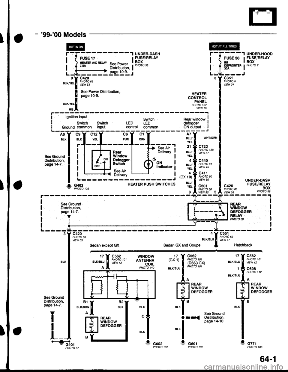
- '99-'00Models
t@
J
See Power0istribution,pag€ 1&9.
r
I
I
Lc420
vtEw 53".*:.f
!
"T.I
FUSE '7HEJT'EF AIC RETAY7JA
UNDER-DASHFUSE/RELAYBOXPHOfO 58
r-r---1 UNDER-HOOD
| ( #tt* IFUsE/RELAY
I t sl*t-' '"o'o'
L-*----J3 Y C3s1
Ss6 Pows Dist bution,pag€ 10-9.
Sn itchLEDcommon
c420PHOTO 63vtEw 53
HEATERCONTROLPANEL
II
I
lgnition inpd
Swiich SlitohGroulld co{Y}rnon inMLEDgontrol
Rear winoow Idofogger Igl",,ry'_l
A6
ALX
S9a €roundDistr&dbn,P.go 1it-7.
c12
YEL
c9
BLK
r'
c6
PUR
c1
ORN
A7BLU/YEL
21
BLU/YEL
BLU/YEL
4(GX 10)
BLU/YEL
8
- Se€ Air ;D6livory
ONIndlcitor
wlIT/GFI{
c723PHO|O 138
c440PHO|O 81vtEw 45
c411PHOTO 60vtEw 60
c501
vtEwss 5
R€aIWlndowDcroggerSultch
56€ AirDeliv€ryL------- ---J
HEATER PUSH SWITCHESUNDEN.DASHFUSE/RELAYBOXPHO|O 5e
I
I
I
I
See GoundDistdbltion,page 14-7.
NEABwlNoolyDEFOGGENF€I.AYPrrolo 59
I
I
I
I
I
cssl
vtEw 47
Halchback
"*1[ ftTi.:-
wtNDowANTENNAcotL{cx'l) T 9,*%,,
",-"",-,
1
[93ff''n'*'
to!.'IFI REARI J I wrNDow
lll
DEFoGGER
".-i."tr ftTi",,'
t V F,9"oB ",erxialul I
ffiff$Eex,"
*"r'
I
I
* cttrPHOfO 10A
Sre GroundDFtrtbditm,pago 1+7.
I
t_
".":il
H
eY
82
ALK*-r"
arr<
-.1
!
S€9 GrolndDistribtdion,pag€ 1+ 10
*r: G401* csozG601
I. G,rc2
PHOIO 57
BEARwtNDowDEFOGGER
64-1
Page 1967 of 2189
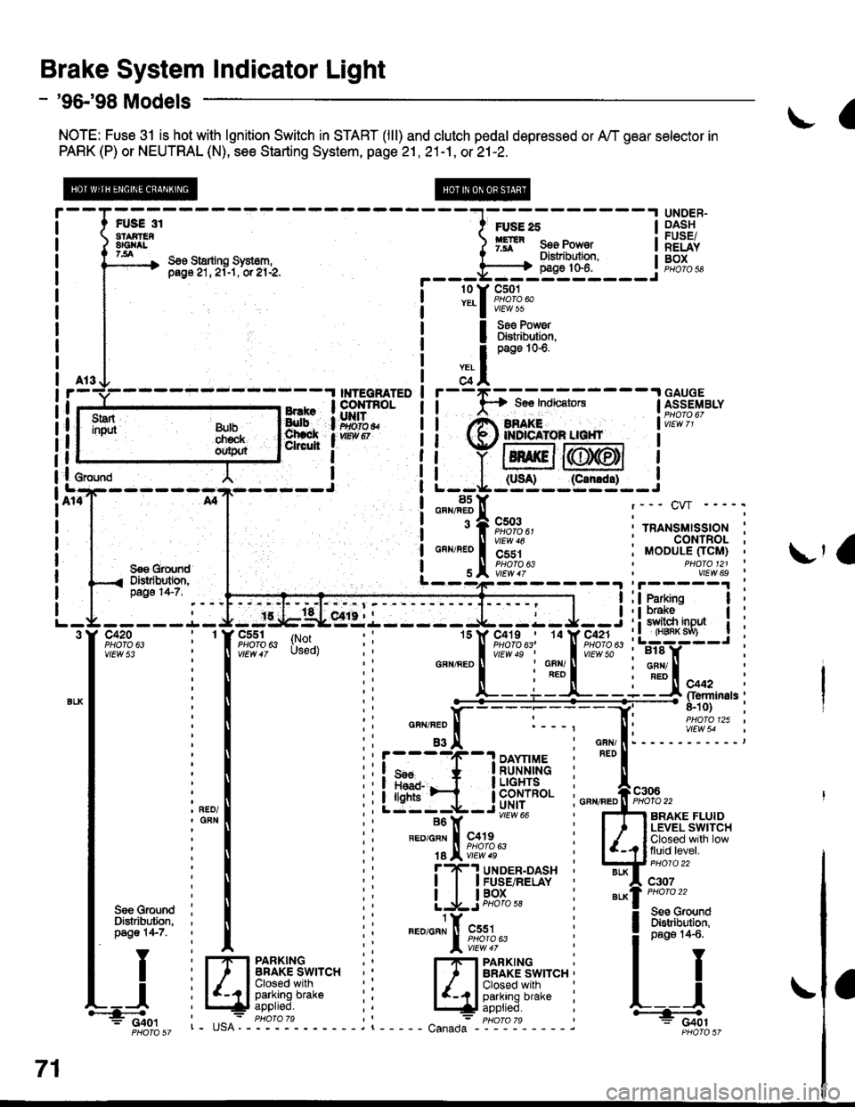
Brake System Indicator Light
- '96-'98 Models
NOTE: Fuse 31 is hot with lgnition Switch in START (lll) and clutch pedal depressed or A,/T gear selector in
PARK (P) or NEUTRAL (N), see Starting System, page 21 , 21-1, or 21-2.
a
FUS€ 31atAirEn8Gl{tt7.all
UNDER-DASHFUSE/RELAYBOXS€o Starling Sysl6m,pag6 21, 2l-1, or el-2,
FUSE 25
ffR s." Ponr"tDistribulion,page 10-6.
rry
I
;?l
r
I
I
I
I
I
I
I
c501PHOTO 60vtEw 55
Ss€ Pow6rDlstribution,page 1G6.
---.I GAUGE$os IndicatorsI ASSEMBLY
i',i!i,I2'
I
I
(slt--95.:l-_i
l8s: GRN/FEDr--- CW ----.
! 3 A cso3 :..^.,"..,"",^.;i "lir%?u' ' rRANsMls-sloN :! ll virw ro : CONTROL ;
99€ grqn'd | ! s I iiiiir^ , vtLw 6s
i o"^r"'o |
'i'jri
| "lw;t,b---4---- 31i3*:'. --l:ffiffi--i
i
---- -.L- J- -:g,tgLesr.l - ---- J--:- J--i : ! 3113'"0* | :-9tF":--T-tY-E;"41i'",
: : lsrss9l;-;?--q1Al" :L:W-J i
-----.1- J- -tlb$Lsr'{.i------ J--:- J--i : ! 31ffi "o* | i-trfr; - -
i
-TFr,lifu:i-|l - - .Tf"*;',r;,f'.F?f;l', i LTS-: :
i I ii
-""'"L--i:t--i3trFlr*n'"i
i mooule ficlrt) iI PHO|O 121 '
:! :i ffitre"ninas;: ll ti n"",".0 ll :---. [: i,119i9."' ''tl
: I :i asi: '.I i eri: -----':::---:
i",",1 iiiffi_il$.t'ii: i"-,s*
vlEw 54
-- vtEot 66 , Ffl anlxe rLUto
i*l
' ".","1;l,"p;a;
illJff*ttt**
u.-u.*il ii [JFHi:"'l*iTfit*,".
I Y i frpanxrxc :' r#"Al[';u3*'""i
I I
U il4.lFfffff'UJ:"" ii EJi,fii,i,"-" i r-j
3"ilj*il
ii
"."""J[ft*,,tl-
i lilt:','x;l
71
i Cior I tE^- phoroTs ,l - : pHoro 7s * C+6tF6r6sz r- usA. - - - - - . t - - - - - canada Froiit sz
Page 1983 of 2189
A/T Gear Position Indicator (conrd)
- How the Circuit Works
With the ignition switch in ON (ll) or START (lll),
voltage is applied to the A,/T gear position indicator.
The A,/T gear position switch provides a ground for
each position. As an input is grounded, its indicator
light comes on. lf you select R, for example, ground
will be provided to the input of the A,/T gear position
indicato( and the R indicator will come on.
With the headlight switch in PARK or HEAD, voltage
is applied to the RED/BLK wire terminal. This
changes the indicator panel illumination from fixed
to controlled by the dash lights dimmer input
through the RED wire.
When the powertrain (all except '96-'98 CVT) or
transmission ('96198 CVT) control module (PCM or
TCM) detects an abnormality in the automatic
transmission control system, or when you request
diagnostic trouble codes through the service check
connector, the PCM or TCM will make the D4 (D for
CVT) indicator light blink.
Refer to the Service Manual (Section 14,
Automatic Transmission) for specific tests or
troubleshooting procedures.
\ia
89-2
Page 1988 of 2189
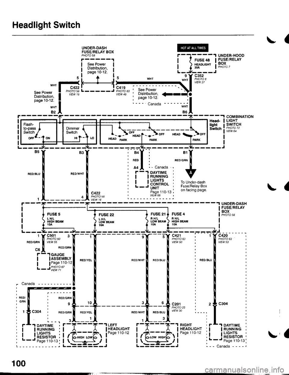
Headlight Switch
(
UNOER-OASHFUSEiRELAY BOXPHOTO 58
Sse PowerDisiribution,page 10-12-
UNDER-HOODFUSE/RELAYBOX
H
FUSE 22L H/ILOIY SEAflt0a
COMBINATIONLIGHTswtTcHHead-lightSwltch
L-----J'SeePower' Distribution,
: Page 10-12.
a
{
UNDER-DASHFUSE/RELAYBOXFUSS 2tF H/LLOW EgAtl
FUSE 4R TIILHIG|{ AEAMt0A
vtEw 53
_ ___:==
1-sr*r"
_
l_-.__
_,_.
it:
".0-", i ".o ".u I i ".o u.,
iti
Iti
llr
lli
lli
--'l --u{.sao,l,. i 2
neourrr I nroerul'/Ftr'o :---,
,.|,___ui
il--Tll''%i'sr"' ii
it@4li**"""li-; s-i5-r i .
I
I
i-t-;;l
1 J lff*n"' IL-.J----J
nrrl'?;Ii
ffif'illi! i
*itn12
HI
- - ) ot[*o1- -] ot. "roo a]ot.HEAD PAnK I panx IPAnK
!a
- -I DAYTIME
IRUNNINGI LIGHTS
! RESTSTOR'- Paqe 110-13
100
Page 1989 of 2189
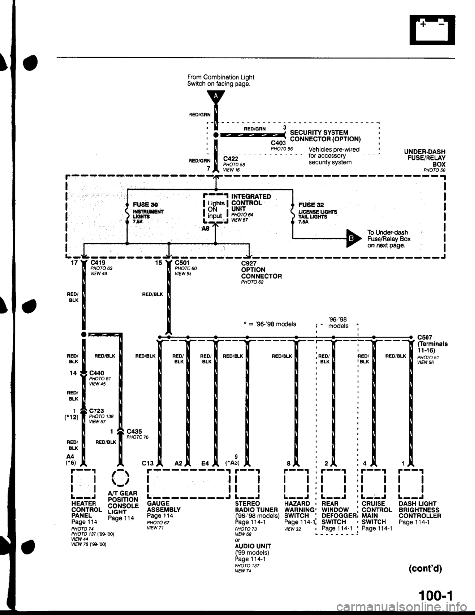
UNDER.DASHFUSE/RELAYBOXPHOTO 58
I
I
I
I
I
I
FUSE 32tpE SE UGfiTStan r|{rs7,54
r--1 l ?EqnATEOI uohts I co rRoL; OFI I UNIT
! input ! im?,t
I
1f12)
To Under-dashFus€/Rglay 8oxon n6xl pag€.
-J---------rt--- ----Jc4r9 15 Y C501 c927PHOfO 6iOPTIONCONNECTORPHOTO 62
nEo/ALK
REO/ALK
* = '96-'98 models
*1[
"-"'['**,.1
_[ *[ ,*,
, FED/
I t:t t;t I
I l:l I ll IL--J ; L--J .L--J
HAZARD , REAR ' CRUISEWARNING. WINDOW :CONTROLSwITcH . DEFoGGER; MAINPage 114-1; SWITCH ' SWITCHvtEv/ 32 , Page114-1 'Pago114-1
c507(Ierminals11n6)
vtEw 56REO/EIK
14
RED/BLK
C't40PHOTO El
c723PHOfO 138
r--1 ;-r
| |ii | il || | | ll I: : A"rr GEAR !------J L--J
EEil'J",- p$i+bd'i 3333fi".' ilB?o'?u"."PANEL Eli"ira Page114 (96-'98 models)Page 114 PHoro 6, Page 1 14.1pHOfO 71 VIEW 71 pHOfO 73PHO|O 1i7 (g9'@l V|EW 6AwEtt/ 41 otv/Ew761ee-oo)
irril?.rJllPage 114-1PHOfO 13/vtEw 74
tl
tl
OASH LIGHTBRIGHTNESSCONTROLLERPage 114-1
(cont'd)
FIJSE l0
100-1
Page 2018 of 2189
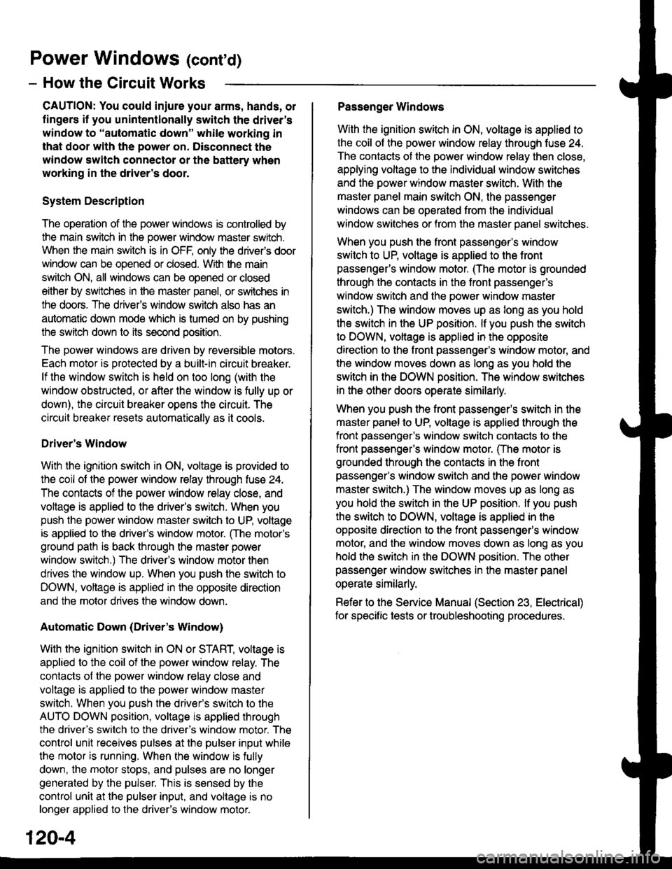
Power Windows (contd)
- How the Circuit Works
CAUTION: You could iniure your arms, hands, or
fingers if you unintentionally switch the driver's
window to "automatic down" while working in
that door with the power on. Disconnect the
window switch conneclot or the battery when
working in the driver's door.
System Description
The operation of the power windows is controlled by
the main switch in the power window master switch.
When the main switch is in OFF, only the driver's door
window can be opened or closed. With the main
switch ON, all windows can be ooened or closed
either by swtches in the master panel, or swttches in
the doors. The driver's window switch also has an
automatic down mode which is tumed on by pushing
the switch down to its second oosition.
The power windows are driven by reversible motors.
Each motor is protect€d by a built-in circuit breaker.
lf the window switch is held on too long (with the
window obstructed, or after the window is fully up or
down), the circuit breaker opens the circuit. The
circuit breaker resets automaticallv as it cools.
Driver's Window
With the ignition switch in ON, voltage is provided to
the coil of the power window relay through fus€ 24.
The contacts of the power window relay close, and
voltage is applied to the driver's switch. When you
push the power window master switch to UP, voltage
is applied to the driver's window motor. (The motor's
ground path is back through the master power
window switch.) The driver's window motor then
drives the window up. When you push the switch to
DOWN, voltage is applied in the opposite direction
and the motor drives the window down.
Automatic Down (Driver's Window)
With the ignition switch in ON or START, voltage is
applied to the coil of the power window relay. The
contacts of the power window relay close and
voltage is applied lo the power window master
switch. When you push the driveas switch to the
AUTO DOWN position, voltage is applied through
the driver's switch to the driver's window motor. The
control unit receives pulses at the pulser input while
the motor is running. When the window is fully
down, the motor stops, and pulses are no longer
generated by the pulser. This is sensed by the
control unit at the pulser input, and voltage is no
longer applied to the driver's window motor.
Passenger Windows
With the ignition switch in ON, voltage is applied to
the coil of the power window relay through fuse 24.
The contacts of the power window relay then close,
applying voltage to the individual window switches
and the power window master switch. With the
master panel main switch ON, the passenger
windows can be ooerated from the individual
window switches or from tho master panel switches.
When you push the front passengsr's window
switch to UP, voltage is applied to the f ront
passenger's window motor. (The motor is grounded
through the contacts in the front passenger's
window switch and the oower window master
switch.) The window moves up as long as you hold
the switch in the UP position. lf you push the switch
to DOWN, voltage is applied in th€ opposite
direction to the front passenger's window motor, and
the window movss down as long as you hold the
switch in the DOWN Dosition. The window switches
in the other doors operate similarly.
When you push the front passenger's switch in the
master panel to UP, voltage is applied through the
front passenger's window switch contacts to the
front passengefs window motor. (The motor is
grounded through the contacts in the front
passenger's window switch and the power window
master switch.) The window moves up as long as
you hold the switch in the UP position. lf you push
the switch to DOWN, voltage is applied in the
opposite direction to lhe front passenger's window
motor, and the window moves down as long as you
hold the switch in the DOWN position. The other
passenger window switches in the master panel
operate similarly.
Refer to the Service Manual (Section 23, Electrical)
for specific tests or troubleshooting procedures.
120-4
Page 2033 of 2189
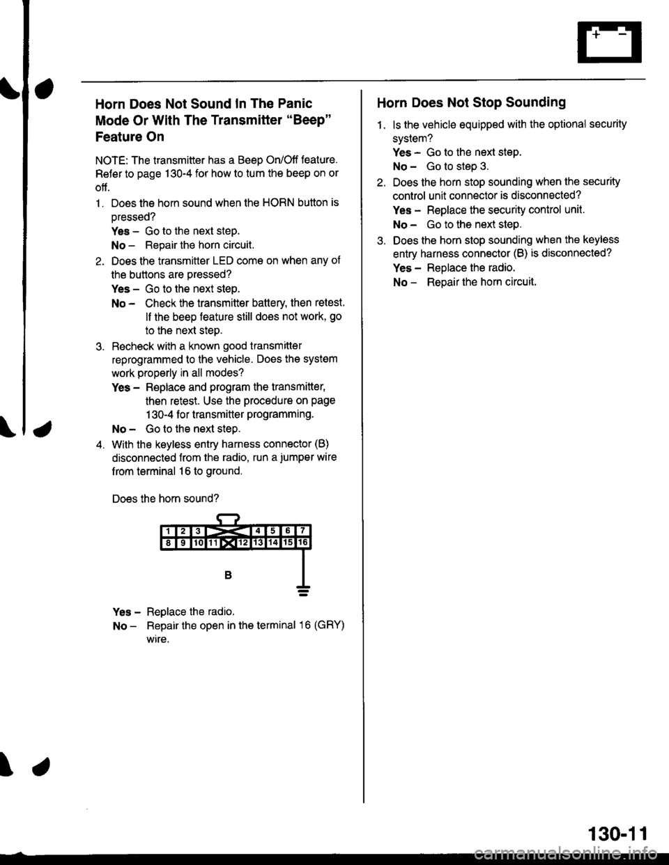
a
Horn Does Not Sound In The Panic
Mode Or With The Transmitter "Beep"
Feature On
NOTE: The transmitter has a Beep On/Off feature.
Refer to page 130-4 for how to tum the beep on or
off.
1. Does the horn sound when the HORN button is
oressed?
Yes - Go to the next steD.
No - Repair the horn circuit.
2. Does the transmittor LED come on when any of
the buttons are pressed?
Yes - Go to the next step.
No - Check the transmitter battery then retest.
ll the beep feature still does not work, go
to the next steo.
3. Recheck with a known good transmitter
reprogrammed to the vehicle. Does the system
work properly in all modes?
Yes - Replace and program the transmitter,
then retest. Use the procedure on page
1 30-4 f or transmitter programming.
No - Go to the next step.
4. With the keyless entry harness connector (B)
disconnected from the radio, run a.iumper wire
f rom terminal 16 to ground.
Does the horn sound?
Yes - Reglace the radio.
No - Repair the open in the terminal 16 (GRY)
wire.
\
Horn Does Not Stop Sounding
1. ls the vehicle equipped with the optional security
system?
Yes - Go to the next step.
No - Go to step 3.
Do€s the horn stop sounding when the security
control unit connector is disconnected?
Yes - Replace the security control unit.
No- Go to the next step.
Does the horn stop sounding when the keyless
entry harness connector (B) is disconnected?
Yes - Reolace the radio.
No - Reoair the hom circuit.
130-11
Page 2037 of 2189
Keyless Receiver Unit Troubleshooting
lf a faulty keyless door lock control unit has one of the symptoms below, turn to the page listed and tollow the
appropriate troubleshooting procedure. lf the symptom seems relatod to an input problem, or is not covered
by the troubleshooting procedures, do the Input Tests on page 130-16. Refer to the circuit schematic on
pages 130-12 and 130-13 as needed.
Symptom Index
Keyless Entry Does Not Work In Any Mode
Ceiling Light Does Not Come On When The Doors Are Unlocked
With TheTransmitter ....
Doors Do Not Unlock Or Lock With The Transmitter . .
Horn Does Not Sound With The Transmitter 'Beep" Feature On .........
Horn Does Not Sound In The Panic Mode ..
HornDoes NotStopSounding ...............
Page 1 30-17
Page 130- 18
Page 130-1 I
Page 130-19
Page 130-19
Page 1 30-19
Page 130-16Input Tests
\.
130-15