Page 1698 of 2189
Power Windows
Master Switch Input Test {Coupe/Hatchback)
NOTE: The control unit is built into the power window master switch, and only controls driver's door window operatlons.
l� Remove the driver's door panel, and disconnect the 12P connector from the master switch.
2. Inspect the connector and socket terminals to be sure they are all making good contact.
. lf the terminals are bent, loose or corroded, repairthem as necessary, and recheck the system.
. lf the terminals look OK, make the following input tests at the connector.- lf a test indicates a problem, find and correct the cause. then recheck the system.- lf all the input tests prove OK, the power window master switch must be faulty; replace it.
23-228
Ware side of female terminals
Page 1702 of 2189
Power Windows
Passenger's Window Switch Test
Coupo/H8tchback:
1. Remove the armrest pocket from the door panel
{see section 20}.
5P CONNECTOR
2. Disconnect the 5P connector from th€ passenger's
window switch.
Sodan:
1. Remove the armrest (see section 20).
Disconnect the 5P connector, then .emove the mount-
ing screw from the passenge/s switch.
PASSENGER'S WINDOW SWITCH
5P CONNECTOR
23-232
Switch sids of 5P t.rminal:
Terminal side olmale terminals
Check for continuity between the terminals in each
switch position according to the table.
12a5
Terminal
il;--lI25
UP
-o
-o
OFF
-o
o--o
DOWNo--o
Page 1703 of 2189
Driver's Window Motor Test
Motor Test:
l. Remove the driver's door panel (see section 20).
Terminal side of male terminals
Disconnect the 4P connector from the motor.
Test the motor in each direction by connecting bat-
tery power and ground according to the table.
CAUTION: When th€ molor stops running, discon-
n€ct one lead immediat€ly.
4. lf the motor does not run or fails to run smoothlv.
reDlace it.
3.
l.,,
Terminal
;."t1."
-_l\1
UPo@
DOWNoo
Puls€r Test:
5. Connect the test leads of an analog ohmmeter to the
No. 3 and No. 4 terminals.
6. Run the motor by connecting power and ground to
the No. 1 and No.2 terminals. The ohmmeter needle
should move back and forth alternately.
23-233
Page 1704 of 2189
Power Windows
Passenger's Window Motor Test
Front:
1. Remove the passenger's door panel (see section
20t.
2. Disconnect the 2P connsctor from the window
moIor.
2P CONNECTOR
\
Terminal side ot msleterminals
3. Check window motor operation by connecting power
and ground according to the table.
CAUTION: When the motor stops running. dbcon-
nest ono load immadiatoly.
4. lf the motor doas not run or fails to run smoothly.
replace it.
Terminal
;;,r";--lI
UP@o
DOWN@
23-234
Re!r:
1. Remove the passenger's door panel {see section
20).
2. Disconnect the 2P connectof from the window
motor.
NOTE: The illustration shows the right rear window
motor; the left rear window motor is symmetrical.
2P CONNECTOR
3. Check window motor operation by connecting power
and ground according to the table.
GAUTION: Whon the motor ctops running, discon-
nact one lead immodiatoly.
4. lJ the moto. does not run or fails to run smoothly.
rcDlace it,
Terminal
DI;t;;---l
UPo@
DOWN@
Page 1715 of 2189
7. Remove th€ two screws, then remove the switch'
Check for continuity between the terminals in switch
position according to the table.
Terminal
t"-"t*
-\23
SET (ON)o--o
RESUI\4E {ON}o----o
lf there is continuity, and it matches the table,
replace the cable reel.
lf there is no continuity in one or both positions,
reDlace the switch.
8.
SET/NESUME
l-l
23-245
11.
q
10.
12.
lf all tests prove OK, reconnect the cable reel and
cable reel sub-harness connector, then reinstall the
steering column covers
Reconnect the driver's airbag connector. and rein-
stall the access panel on the steering wheel.
Reconnect the battery positive cable, then the nega-
tive cable.
After connecting the airbag connectors, confirm
proper system operation; Turn the ignition switch ON
(ll); the SRS indicator light should come on for about
six seconds and then go off.
Enter the anti-theft code for the radio, then enter the
customer's radio station presels {'99 -00 models)'
Page 1717 of 2189

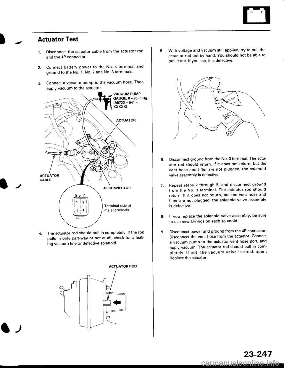
)Actuator Test
't.Disconnect the actuator cable from the actuator rod
and the 4P connector.
Connect battery power to the No 4 terminal and
ground to the No. 1, No. 2 and No. 3 terminals.
Connect a vacuum pump to the vacuum hose Then
apply vacuum to the actuator.
2.
VACUUM PUMPGAUGE,0 - 30 in.Hg.
{A973X - 041 -
xxxxxl
ACTUATOR
,lP CONNEcToR
Terminalside o{male termrnals
4. The actuator rod should pull in completely. lf the rod
pulls in only pan-way or not at all' check for a leak-
ing vacuum line or defective solenoid.
ACTUATOF ROD
l-t
23-247
5. With voltage and vacuum still applied, try to pull the
actuator rod out by hand. You should not be able to
oull it out. ll you can, it is defective
1.
Disconnect ground from the No.3 terminal. The actu-
ator rod should return lf it does not return, but the
vent hose and filter are not plugged, the solenoid
valve assembly is defective.
Repeat steps 2 through 5, and disconnect ground
from the No. 1 terminal. The actuator rod should
return. lI it does not return, but the vent hose and
filter are not plugged. the solenoid valve assembly
is defective.
It you replace the solenoid valve assembly, be sure
to use new O-rings on each solenoid.
Disconnect power and ground from the 4P connector.
Disconnect the vent hose from the actuator. Connect
a vacuum pump to the actuator vent hose port, and
apply vacuum. The actuator rod should pull in com-
pletely. lf not, the vacuum valve is stuck open.
Replace the actuator'
8.
Page 1721 of 2189

Power Door Locks
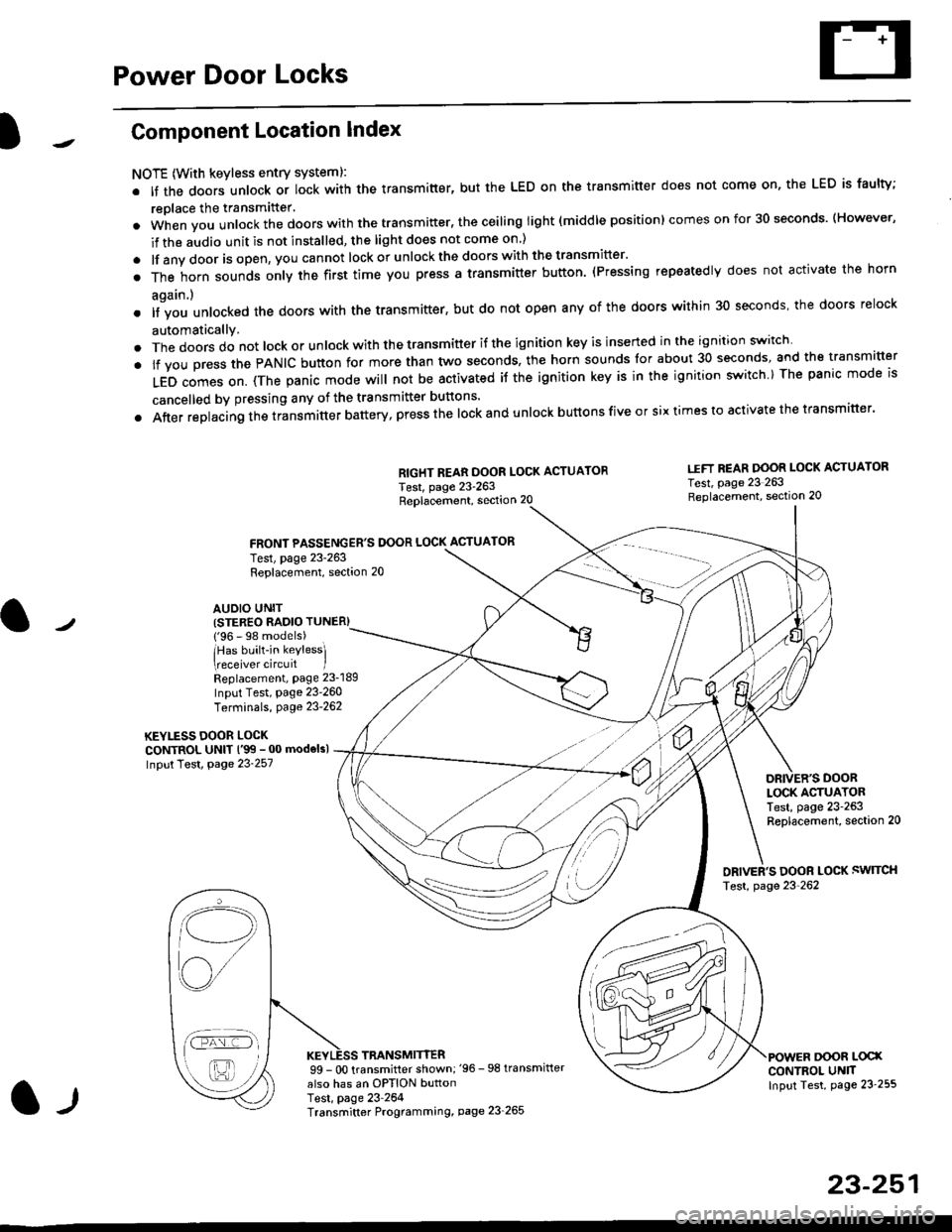
Component Location Index
NOTE (With keyless entry systeml:
. It the doors unlock or lock with the transmitter, but the LED on the transmitter does not come on, the LED is faulty;
replace the transmitter'
. when vou unlock the doors with the transmitter, the ceiling light (middle position) comes on for 30 seconds. (However,
if the audio unit is not installed, the light does not come on )
. lf any door is open, you cannot lock or unlockthe doors with the transmitter'
. The horn sounds only the first time you press a transmitter button. (Pressing repeatedly does not activate the horn
again.)
o lf vou unlocked the doors with the transmitter, but do not open any of the doors within 30 seconds, the doors relock
automatically.
. The doors do not lock or unlock with the transmitter if the ignition key is inserted in the ignition switch
. lf you press the PANIC button for more than two seconds, the horn sounds for about 30 seconds, and the transm'fer
LED comes on. (The panic mode will not be activated iJ the ignition key is in the ignition switch ) The panic mode is
cancelled by pressing any of the transmitter buttons'
o After replacing the transmitter battery, press the lock and unlock buttons five or six times to activate the transmitter'
Replacement, section 20
FRONT PASSENGER'S DOOR LOCK ACTUATOR
RIGHT REAR DOOR LOCK ACTUATOR
Test, page 23-263
I.IFT REAR DOOR LOCK ACTUATOR
Test, page 23 263Replacement, section 20
LOCK ACTUATORTest, page 23-263Replacement, section 20
ORIVER'S DOOR LOCK SWITCH
Test, page 23'262
DOOR L@XCONTROL UN]TInput Test, page 23 255
23-251
Test, page 23-263Replacement, section 20
AUDIO UNIT(STER€O RADIO TUNER)
{'96 - 98 models)
lHas built-in keylessl
eceiver circuit IReplacement, page 23-189
Input Test, page 23-260
Terminals, page 23-262
KEYLESS DOOR LOCKCONTROL UNIT l'99 - 00 modelsl
Input Test, Page 23-257
l-l
TRANSMITTER99 - 0O transmitter shown;'96 -98 transmifter
also has an OPTION buttonTest, page 23-264Transmitter Programming, page 23_265
Qi,,a/
/----
L(ru
i'.-8,-'l
/'-'6
Page 1727 of 2189
Control Unit Input Test ('96 - 98 models and'99 - 00 models without
Keyless Entry System)
1. Remove the driver's door panel (see section 20).
2. Disconnect the 12P connector from the control unit.
3. Inspect the connector and socket terminals to be sure they are all making good contact
a lf the terminals are bent, loose or corroded, repair them as necessary, and recheck the svste-
. lf the terminals look OK, make the following input tests at the connector.
- lf any test indicates a problem, find and correct the cause, then recheck the syslem
lf all the input tests prove OK, the control unit must be faulty; replace it.
.I2P CONN€CTOR
Wire side o{ femele terminals
*: With keyless entry system
l-llcont d)
23-257
YEL/RED
BLU/RED
15
1812
BLU/WHT