Page 1403 of 2189
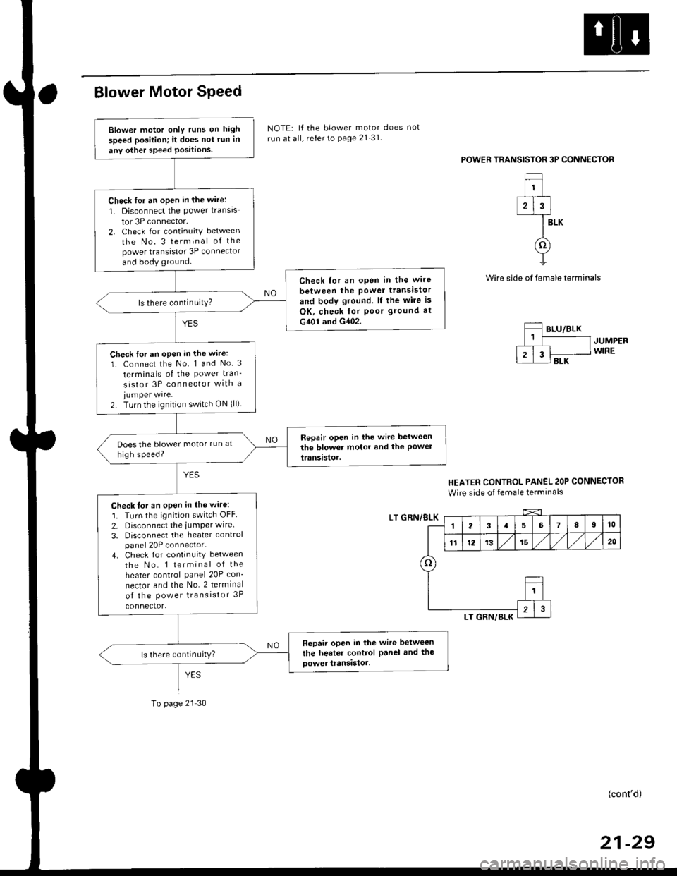
BIower Motor Speed
To page 21 30
NOTE: lf the blower motor does not
run at all, refer to page 21-31.
POWEB TRANSISTOR 3P CONNECTOR
BLK
Wire side ol female terminals
JUMPERWIRE
HEATER CONTROL PANEL 2OP CONNECTOR
Wire side of female terminals
LT GRN/8LK
(cont'd)
21-29
Blower motor only runs on high
speed position; it does not run in
any other speed Positions
Check for an open in lhe wire:
1. Disconnect the power transis
tor 3P connector,2. Check for continuity between
the No. 3 terminal of thepower transistor 3P connector
and body ground.
Check tor an open in the wire
between the Power ttansistor
and body gtound. lf the wire is
OK, check for poor ground at
G401 and G402.
ls there continuity?
Check tor an open in the wire:
1. Connect the No. 1 and No 3
terminals of the Power tran_
sistor 3P connector wlth ajumper wire.2. Turn the ignition switch ON {ll)
Repair open in the wire belweenthe blower motor and the Powettranststor.
Check tor an open in the wire:
1. Turn the ignition switch OFF
2. Disconnect the iumPer wire.
3. Disconnect the heater controlpanel 20P connector.4. Check for continuity between
the No. 1 terminal of the
heater control panel 20P con-
nector and the No. 2 terminal
of the Power transistor 3P
Repair open in the wire between
the heater control Panel and tho
oower transistor,ls there continurty)
3
o
Page 1404 of 2189
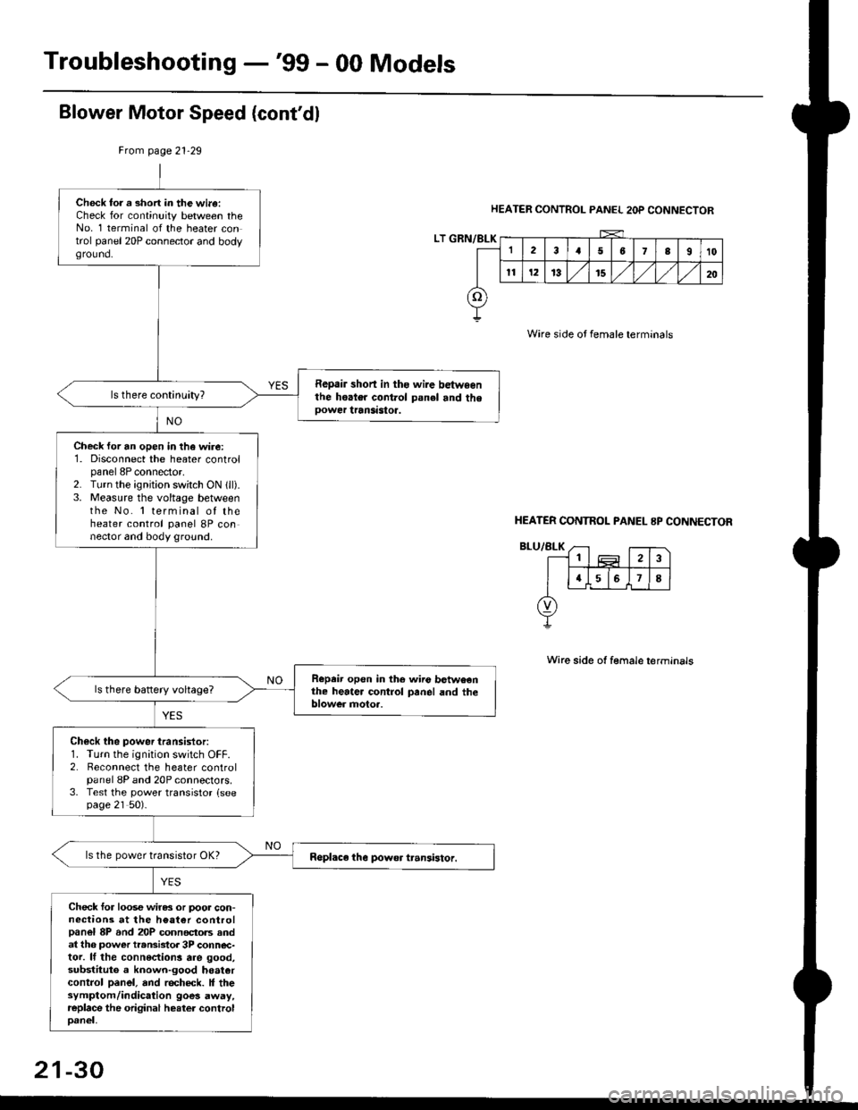
Troubleshooting -'99 - 00 Models
Blower Motor Speed (cont'dl
HEATER CONTROL PANEL 2OP CONNECTOR
Wire side oJ female terminals
Wire side ot female terminals
Frcm page 21.29
LT GRN/BLK
Check tor a short in the wi.a:Check for continuity between theNo. 1 terminal of the heater control panel 20P connector and bodyground.
Repair short in ths wire betwsenthe hoater control panel and theoower transastoa.
Check for an open in the wire:1. Disconnect the heater controlpanel 8P connector,2. Turn the ignjtion switch ON 1ll).3. Measure the voltage betweenthe No. 'l terminal of theheater control panel 8P connector and body ground.
Repeir open in the wiio betweenthe heater control panel and theblower motoa.
Check the power transistor:1. Turn the ignition switch OFF.2. Reconnect the heater controlpanel 8P and 20P connectors.3. Test the power transistor {seepage 21 50).
ls the power transistor OK?
Check for loos€ wiras or poor con-nections at the h€at€r controlpanel 8P and 20P connectols andat th6 power transistor 3P conn€c-tor. lf the connections are good,substituto a known-good hoatercontrol panel, and recheck. It thesymptom/indication goes away,replace the original heater controloanel,
HEATER CONTNOL PANEL 8P CONNECTOR
21-30
Page 1405 of 2189
Blower Motor
BLOWER MOTOR 2P CONNECTOR
Wire side of lemale terminals
JUMPERWIRE
(cont'd)
21-31
Blower motor does not run at all.
Check the No. 55 (40 A) Iuse in
the under-hood fuse/relay box,
and the No. 17 (7.5 A){use in the
undeFdash fuse/relay box.
Boplace th€ fuse(3), and rechock.
Check th€ blow€r motor Powelsupply circuit:1. Disconnect the blower motor
2P connector.2. Turn the ignition switch ON {ll).
3, Measure the voltage between
the No. 1 terminal oI the blow
er motor 2P connector and
body ground.
ls there battery voltage?
Check tha blower motor:
1. Turn the ignition switch OFF
2. Reconnect the blower motor
2P connector.3. Connect the No.2 terminal o{
the blower motor 2P connector to bodv ground with a
tumper wire.4. Turn the ignition switch ON {ll}
Does the blower motor run?
fo page 21-32
To page 21-33
Page 1406 of 2189
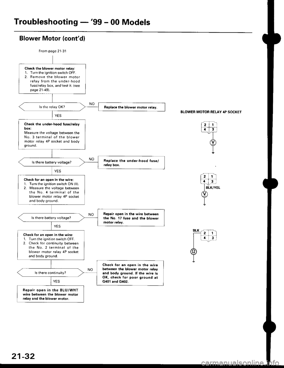
Troubleshooting -'99 - 00 Models
From page 21-31
Check the blower motor relay:1. Turn the ignition switch OFF.2. Remove the blower motorrelay from the under hoodfuse/relay box, and test it- (seepage 21'49).
Replace the blower motor relay.
Check the under-hood tuse/relaybox:Measure the voltage between theNo. 3 terminal of the blowermotor relay 4P socket and bodyground.
Check tor an open in the wire:1. Turn the ignition switch ON (ll).
2. Measure the voltage betweenthe No. 4 terminal of theblower motor relay 4P socketand body ground.
Repair opon in lhe wire betweenthe No. 17 fuse and the blowetls there battery voltage?
Check for an open in the wire:1. Turn the ignition switch OFF.2. Check for continuity betweenthe No. 2 terminal of theblower motor relay 4P socketand body ground.
Check lor an ooen in the wirebetween the blowor motor relayand body ground. It the wiie isOK, check for poor ground atG401 and G402.
ls there continuityl
Repair open in the BLU/WHTwiae between the blower motorrelay and the blower motor,
BLOWER MOTOR RELAY 4P SOCKET
21-32
Page 1407 of 2189
From page 21 31
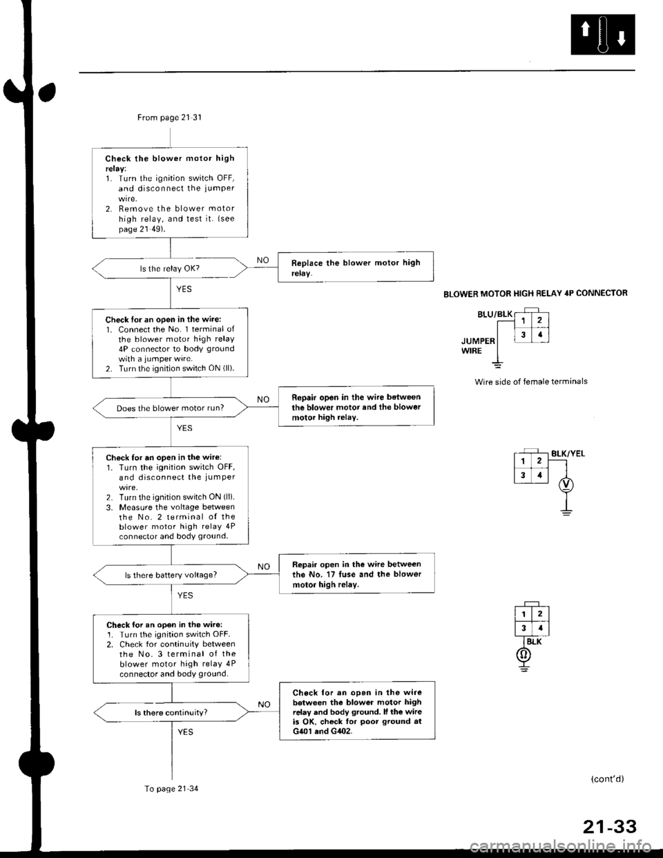
ls there continuity?
YES
Check the blower motor highrelay:1. Turn the ignition switch OFF,and disconnect the iumPer
2. Remove the blower motor
high relay, and test it. {seepage 21 49).
Check lor an open in the wire:1. Connect the No. 1 terminal ofthe blower motor high relay4P connector to body ground
with a jumPer wire.2. Turn the ignition switch ON (ll).
Repair open in the wire belweenthe blower motor and the blowermotor high rolay.Does the blower motor run?
Check for an op6n in the wir6:1. Turn the ignition switch OFF,and disconnect the iumPer
2. Turn the ignition switch ON (ll).
3, Measure the voltage betweenthe No. 2 terminal of theblower motor high relay 4Pconnector and body ground.
Repair open in the wire betweenthe No. 17 fuse and the blowor
motor high relay.ls there battery voltage?
Check for an open in the wire:1. Turn the ignitaon switch OFF.2. Check for continuity betweenthe No.3 terminal of theblower motor high relay 4P
connector and body ground.
Ch6ck lor an op.n in the wirebotween the blower motor highrelay and body ground. ll the wireis OK, ch6ck for poot ground atG401 end G402.
To page 21 34
BLOWER MOTOR HIGH RELAY 4P CONNECTOR
JUMPERWIRE
Wire side of female terminals
(cont'd)
21-33
Page 1409 of 2189
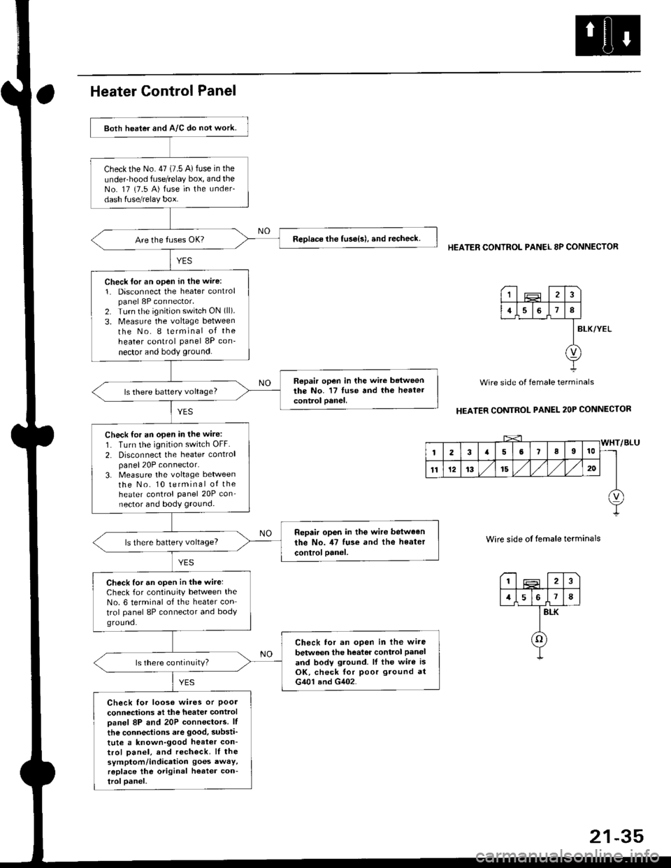
Both heater and A/C do nol work.
checkthe No.47 (7.5 A)fuse in the
under-hood fuse/relay box, and theNo. 17 {7.5 A) fuse in the under-
dash fuse/relay box.
ReDlace the tuse{s), and recheck.
Check lor an open in the wire:
1. Disconnect the heater controlpanel 8P connector,2. Turn the ignition switch ON (ll).
3. Measure the voltage between
the No. I terminal of the
heater control panel 8P con-
nector and body ground.
Repair open in the wire betweenthe No. '17 luse and th6 heatercontrol oanel,ls there battery voltage?
Check for an open in the wire:
1. Turn the ignition switch OFF.
2. Disconnect the heater controlpanel20P connector.3. Measure the voltage lletweenthe No. 10 terminal of theheater control Panel 20P con-nector and body ground.
Repair op6n in the wir€ between
the No. il7 tuse and the heater
controloanel,ls there battery voltage?
Check for an open in the wite:Check for continuity between theNo. 6 terminal of the heater con
trol panel 8P connector and bodyground.
Ch6ck tor an open in lhe wire
betwoen the heator control Paneland bodv ground. lf the wire isOK, check for poor ground atG401 and G402.
ls there continuity?
Check for looso wires or Poolconneciions at the heater controloanel 8P and 20P connectors. lf
the connections are good, substi'
tute a known-good heat€r con-trol Danel, and recheck. lI thesymptom/indication goes awaY,r6place the original h€ater con-troloanel.
HEATER CONTROL PANEL 8P CONNECTOR
BLK/YEL
Wire side of female terminals
HEATER CONTROL PANEL 2OP CONNECTOR
Wire side of temale terminals
I2
1578
BLK
o
1
4I
v
Page 1411 of 2189
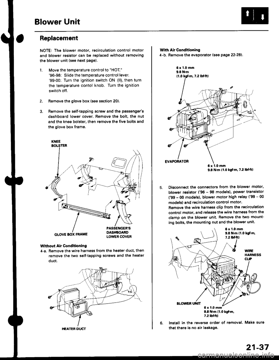
Blower Unit
Replacement
NOTE: The blower motor, recirculation control motor
and blower resistor can bs replacsd without rsmoving
th€ blower unit (see neld Page).
1. Move the temperature control to "HOT."
'96-98: Slide the temperature control lever.'99-00: Turn the ignition switch ON (ll), then turn
the temperature contol knob. Turn the ignition
switch off,
Remove the glovs box (ses ssction 20),
R€move ths s6lf-tapping screw and ths passsng6r's
dashboard low€r cover. Removo the bolt, the nut
and the kn€e bolst€r, then remove the fiv€ bolts and
the glove box trame,
Without Air Condhioning
4-a. Remove the wiro harness from the h68t€r duct, then
remove the two self-tapping scrsws and the heatsr
duct.
KNEE
GLOVE BOX FRAME
HEATER DUCT
21-37
Wrth Air Conditioning
4-b. Removo th6 ev8porator (sss pago 22-28).
6x1.0m|n9.8 N'm
6x1.0mm9.8 N'm lt'o tgf'm, t.2 lb{'ttl
Disconnoct the connectors trom th€ blower motor,
blowor r6sistor {'96 - 98 models), power transiator
('99 - 0O modsls), blowor motor high telay ('99 - 00
models) and recirculation control motor.
R€mov€ ths wiro harnoss clip from tho recirculation
control motor, and release the wir6 harnsss from ths
clamo on the blowor unit. Remove the two mount-
ing bolts, tho mounting nut and ths blowor unit'
9.8 .m 11.0 tgfm,1.2 tblfrl
lnstall in ths reverso order of removal. Mako surs
that thsre is no air leaka96.
6x1.0mm9,t N'm 11.0lgi.m,7.2 tbf.fil
Page 1419 of 2189
Adjustment -'99 - 00 Models
1. From under the hood, open the cable clamp, then
disconnect the heater valve cable from the heater
valve arm.
From under the dash. disconnect the heater valve
cable housing from the cable clamp, and disconnect
the heater valve cable from the air mix control arm.
HEATER VALVE CABLE
Set the temperature control dial on MAX COOL with
the ignition switch ON {ll).
Attach the heater valve cable to the air mix control
arm as shown above. Hold the end of the heater
valve cable housing against the stop, then snap the
heater valve cable housing into the cable clamp.
HEATER VALVE ARM
5. From under the hood. turn the heater valve arm to
the fullv closed oosition as shown, and hold it,
Attach the heater valve cable to the heater valve
arm, and gently pull on the heater valve cable hous-
ing to take up any slack, then install the heater valve
cable housing into the cable clamp.
HEATER VALVE ARM
21-45