1999 HONDA CIVIC trunk mat
[x] Cancel search: trunk matPage 43 of 2189
Lift and SupPort Points
L,O
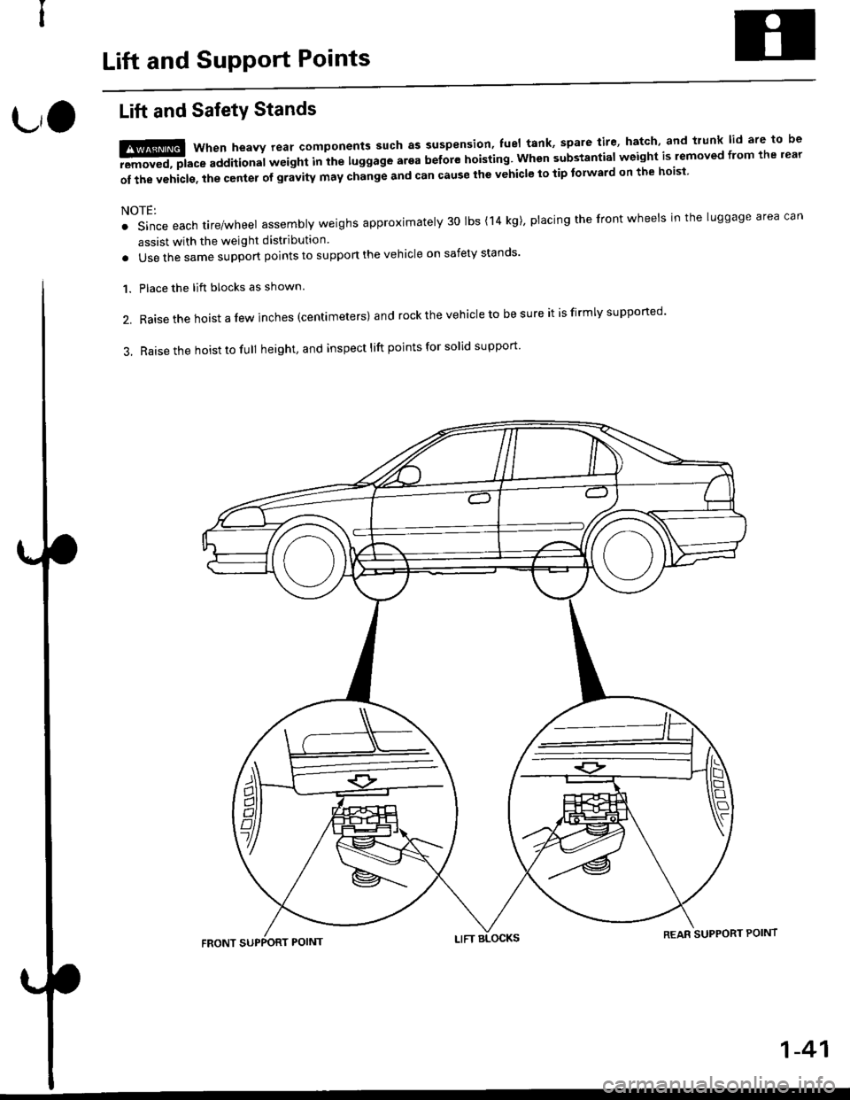
Lift and SafetY Stands
t!ffi when heavv rear components such as suspension' fuel tank' spare tire' hatch' and trunk lid are to be
-aEremoved, place additional wetght Inihe luggage arga before hoisting. when substantial weight is lemoved from the rear
of the vehicls. the center of gravity may change and can cause the vehicle to tip tolward on the hoisi
NOTE:
. Since each tire/wheel assembly weighs approximately 30 lbs (14 kg)' placing the front wheels in the luggage area can
assist with the weight distribution
. Use the same support points to suppon the vehicle on safety stands'
Place the lift blocks as shown.
Raise the hoist a lew inches (centrmeters) and rock the vehicle to be sure it is firmly supported'
Raise the hoist to full height, and inspect lift points for solid support
1.
2.
3.
REAR SUPPORT POINT
1-41
Page 67 of 2189
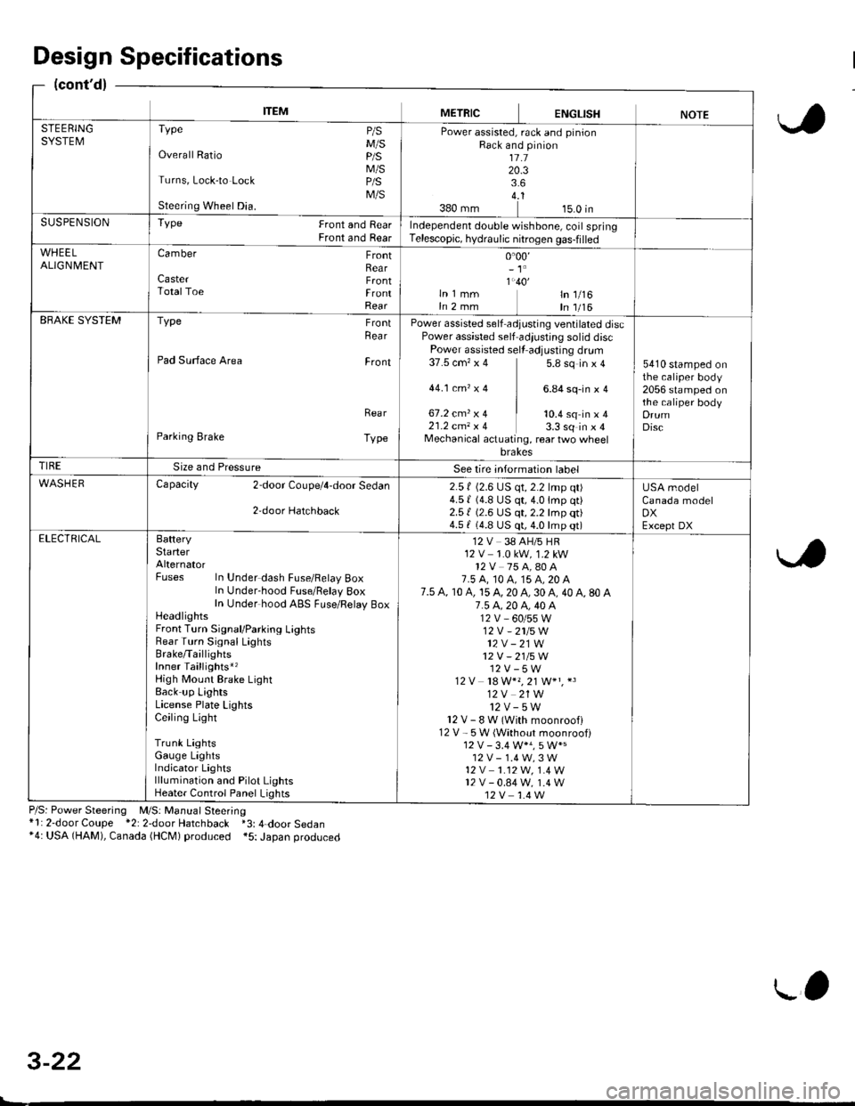
ITEMMETRICENGLISHNOTESTEERINGSYSTEMTvpe P/sM/SOverall Ratio p/S
M/STurns, Lock-to Lock p/S
M/SSteering Wheel Dia.
Power assisted, rack and pinionRack and pinion1l.120.33.64..1380 mm 15.0 inSUSPENSIONTYPe Front and RearFront and RearIndependent double wishbone, coil springTelescopic, hydraulic nitrogen gas-filled
WHEELALIGN| 4ENTCamber FrontRearCaster F.ontTotalToe FrontRear
0.00,- 't'
1.40'ln 1 mm ln 1/16In 2 mm In 1/16EBAKE SYSTEMType FrontRea r
Pad Surface Area Front
Rea r
Parking Brake Type
Power assisted self adjusting ventilated discPower assisted self adiustjng solid discPower assisted sell adjusting dr!m37.5 cm'�x 4 5.8 sq in x 4
44.1ctn,x4 ] 6.84sq-inxa
67.2 cmz x 4 | to.+ sq in ' I21.2 cm, x 4 3.3 sq in x 4Mechanical actuating, rear two wheelbrakes
5410 stamped onthe caliper body2056 stamped onthe caliper bodyDrumDisc
TIRESize and PressureSee lire intormation label
WASHERCapacity 2door Coupe/4,door Sedan
2,door Hatchback
2.5 f (2.6 LJS qt, 2.2 lmp qt)4.5 | (4.8 US qt,4.0lmp qt)2.51 (2.6 US qt, 2.2 lmp qt)4.5 f (4.8 US qt, 4.0 lmp qt)
USA modelCanada modelDXExcept DXELECTRICALBafteryStarterAlternatorFuses In Under dash Fuse/Felay BoxIn Under-hood Fuse/Belay 8oxIn Under hood ABS FLrse/Relay BoxHeadlightsFront Turn Signal/Parking LightsRear Turn Signal LaghtsBrake/TaillightsInner Taillights*,High Mount Brake LightBack up LightsLicense Plate LightsCeiling Light
Trunk LightsGauge LightsIndicator Lightslllumination and Pilot LightsHeater Control Panel Lights
12 V 38 AH/5 HR12 V 1.0 kW, 1.2 kW12V 75 A,80 A7.5 A, t0 A, 15 A, 20 A7.5 A, 10 A, 15 A, 20 A, 30 A, 40 A, 80 A7.5 4.20 A, 40 A12V_60/55W12V -2115W
12V - 21W12V - 21/5W12V-5W12 V 18 W*" 21 W+" *3
12V 21W12v-5wl2V-8W(Withmoonroofl12 V - 5W (Without moonroof)
12V-1.4W,3W't2 v 1.12W. 1.4 W12v-0.84w, 1.4 W12V 1.4 W
Design Specifications
(cont'd)
P/S: Power Steering M/S: Manual Steering*l: 2-door Coupe *2: 2door Hatchback *3: 4-door Sedan*4: USA (HAM), Canada (HCM) produced *5: Japan produced
3-22
L'
Page 72 of 2189
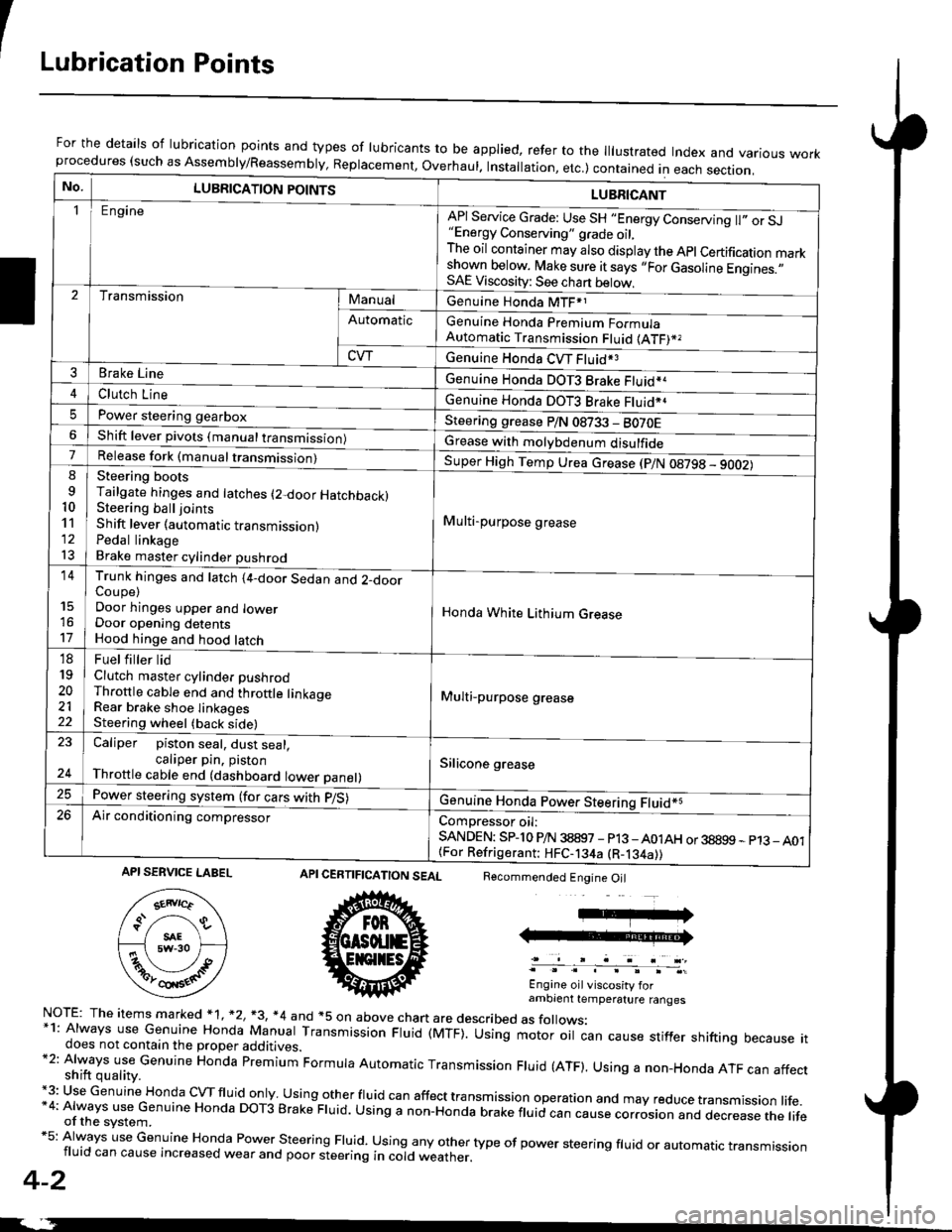
ILubrication Points
For the details of lubrication points and types of lubricants to be applied, refer to the lllustrated Index and various workprocedures (such as Assembly/Reassembly, Replacement, Overhaul. Installation, etc.) contained in each section.
No.LUBRICATION POINTS
Engine
LUBRICANT
"Energy Conserving" grade oil,The oil container may also display the Apl Certification markshown below. Make sure it says ,,For Gasoline Engines.,,SAE Viscosity: See chart below,
I
TransmissionManualGenuine Honda MTF*1
Genuine Honda Premium FormulaAutomatic Transmission Fluid (ATF)*,
Genuine Honda CVT Fluid*3
Genuine Honda DOT3 Brake Fluid*a
Automatic
CVT
3Brake Line
ClL,tci t""e4
I
Genuine Honda DOT3 Brake Fluid*aPower steering gearboxSteering grease P/N 08733 - BO70EShift lever pivots (manual transmission)Grease with molybdenum disulfide7-:ti
9
10'l'l
l3
14
't7
18
19
20
2122
Release fork (manual trancmi
Shift lever (automatic transmission)Pedal linkageBrake master cylinder pushrod
Super High Temp Urea crease (p/N 08798 - 9OO2)
i Multi-purpose grease
I
I
Honda White Lithium Grease
Multi-purpose grease
Silicone grease
@
Trunk hinges and latch (4-door Sedan and 2-doorCoupe)Door hinges upper and lowerDoor opening detentsHood hinge and hood latch-FUet T ter ttd
Clutch master cylinder pushrodThrottle cable end and throttle linkageRear brake shoe linkagesSteering wheel (back side)
23
E-
Caliper piston seal, dust seal,caliper pin. pistonThrottle cable end (dashboard lower panel)
Power steering system (for cars with p/S)
Air conditioning compressorComDressor oil:SANDEN: SPlo P/N 38897 - p13 -A01AH or 38899 - p13_ A01{For Refrigerant: HFC-134a (R-134a))
CERTIFICATION SEAL
ffi
NorE: The items m arked * 1, *2, +3, *4 and +5 on above chan are described as folows:*1: Always use Genuine Honda Manual Transmission Fluid (MTF). Using motor oil can cause stiffer shifting because itdoes not contain the proper additives.*2: Always use Genuine Honda premium Formula Automatic Transmission Fluid (ATF). Using a non-Honda ATF can affectshift quality.+3: Use Genuine Honda cVTfluid only usingotherfluid can affect tra nsmission operation and may reduce transmission life.*4: Always use Genuine Honda DoT3 Brake Fluid. Using a non-Honda brake fluid can cause corrosion and dec.ease the lifeof the svstem.*5: Always use Genuine Honda Power steering Fluid. using any other type of power steering fluid or automatrc transmissionfluid can cause increased wear and poor steering in cold weather.
4-2
Recommended Engine Oil
Engine oil viscosity forambrent temperature ranges
API SERVICE LABEL
Page 1292 of 2189
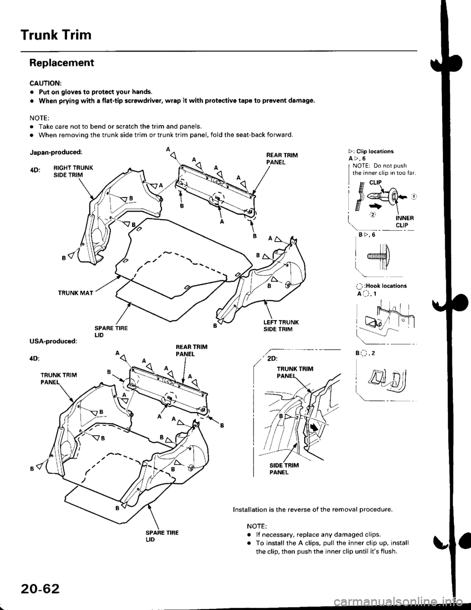
Trunk Trim
Replacement
CAUTION:
. Put on gloves to proteci your hands.
. When prying with a flat-tip screwdriver, wrap it with protestive tap€ lo prevent damage.
NOTE:
. Take care not to bend or scratch the trim and panels.
. When removing the trunk side trim or trunk trim panel, fold the seat-back forward.
Japan-produced:
4D: RIGHT TRUNKSIDE TRIM
TRUNK MAT
1B
REAR TRIMPANEL
>: Clip locationsa>,6
a:-) ,2
I g cLlP ^
l#srq-'
| ' |NNER\- crLP
B >,6
NOTE: Do not push
the inner clip in too far.
IJ
LTro
i ) :Hook locations
A i--) , r
' 2D:
TRUNK TRIM
Installation is the reverse of the removal procedure.
NOTE:
. lf necessary. replace any damaged clips.
. To install the A clips. pull the inner clip up. install
the clip, then push the inner clip until it's flush.
(
,- --
/'/ \--
/ --
20-62
Page 1312 of 2189
Rear Seat
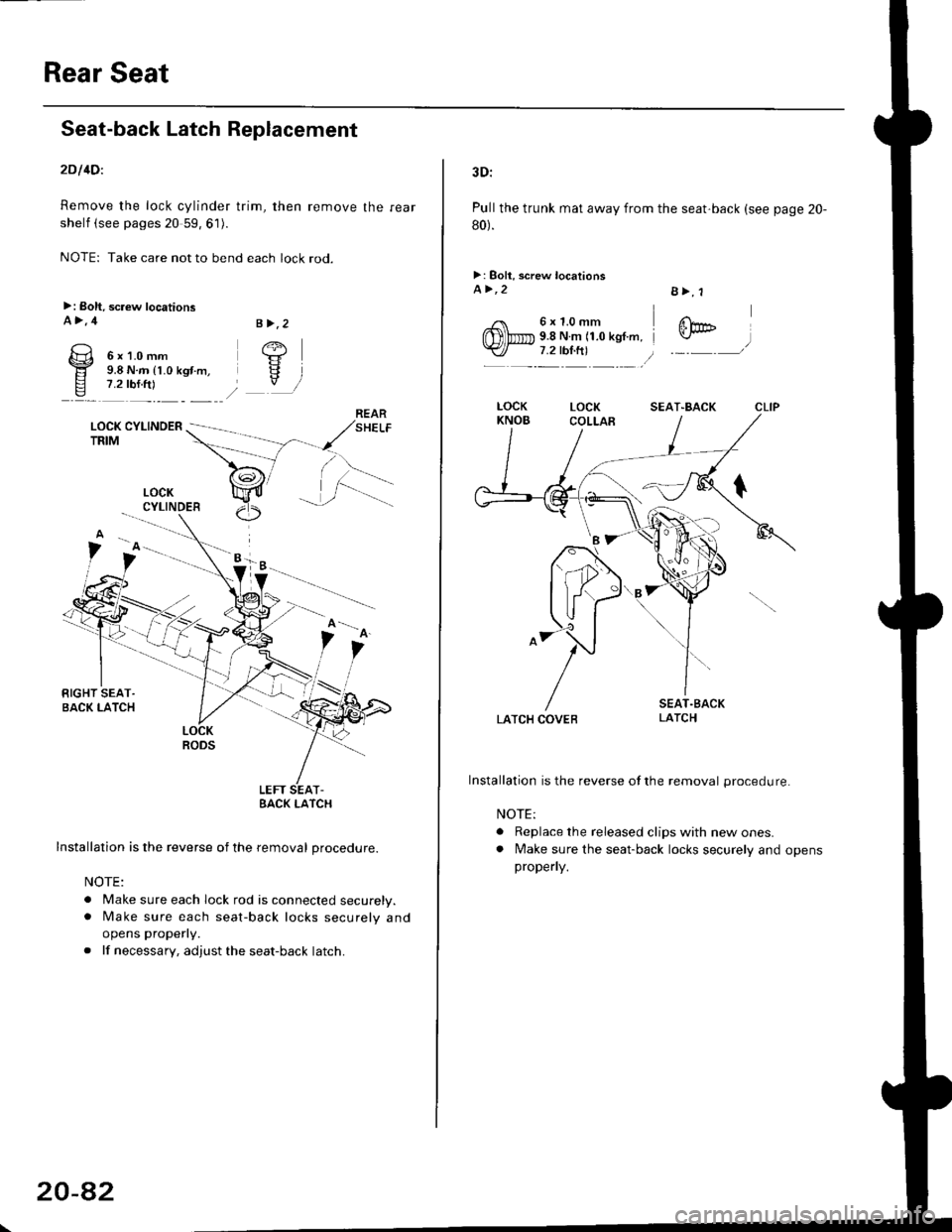
Seat-back Latch Replacement
2Dl4Dl
Remove the lock cylinder trim, then remove the rear
shelf (see pages 20 59, 61).
NOTE: Take care not to bend each lock rod.
>: Boh, screw locationsA>,4
6x1.0mm9.8 N.m (1.0 kgt.m,7.2 rbf.ftl
LOCK CYLINOERTRIM
.i.-::
LOCKRODS
LEFT SEAT-EACK I-ATCH
Installation is the reverse of the removal procedure.
NOTE:
. Make sure each lock rod is connected securely.. [/ake sure each seat-back locks securely and
opens properly.
. lf necessary, adjust the seat-back latch.
B >,2
/+j
V
LOCKCYLINDER
20-8�2
3D:
Pull the trunk mat away from the seat'back (see page 20-
80).
>: Boll, screw locationsa>,2
6x1.0mm9.8 N.m (1.0 kgf.m,7.2 tbl.ft)
B>, 1
@
LATCH COVEB
Installation is the reverse ofthe removal procedure.
NOTE:
. Replace the released clips with new ones.. lvlake sure the seat-back locks securely and opensproperly.
SEAT"BACK
Page 1338 of 2189
Opener Cables
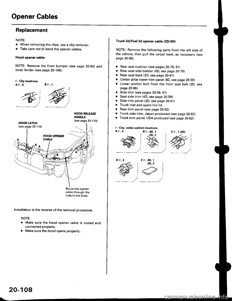
Replacement
NOTE:
t When removing the clips. use a clip remover.. Take care not to bend the opener cables.
Hood op€ne. cable:
NOTE; Remove the front bumper (see page 20-94) andinner fender (see page 20-106).
>: Clip loc.tionsA >,5 B>, 1
ry)
g
HOOD REI.TASEHANDI.I(see page 20-110)
cable through thehote in th6 body.
Installation is the reverse of the removal procedure.
NOTE:
a Make sure the hood opener cable is routed andconnected properly.
. Make sure the hood opens properly.
20-10a
Tlunk lid/Fuel lid opener cabte (2Dl4D):
NOTE: Remove the following parts from rhe Ieft side ofthe vehicle, then pull the carpet back, as necessary {seepage 20-66).
. Rear seat cushion (see pages 20-79, 81). Rear seat side bolster (4D, see page 20,79). Rear seat-back (2D, see page 20-81). Center pillar lower trim panel (4D, seepage20-59)o Lower anchor bolt from the front seat belt {2D. seepage 20-86)
. Side trim (see pages 20-59, 61). Seat side trim (4D, see page 20-59). Side trim panel (2D, see page 20-61). Trunk mat and spare tire lid. Reartrim panel (see page 20-62). Trunk side trim, Japan-produced (see page 20-62). Trunk trim panel, USA-produced (see page 20-62)
>r Clip, cable cushion locationsA >,4 B >,4D_ 1c >, 1 l4D)2D,2
t@#lB
_ : _/ _-___)
E >,4D, 12D,2
@i
_ _,, -/
D>,3
Page 1817 of 2189

Contents
How to Use This Manual ICircuit Schematics (see Circuit Index)Fuse/Relaylnformation 6Ground-to-Componentslndex 6-6ComponentLocationPhotooraohs 201Conriector Views 202
Circuit Index
Accessory power socket 155Air conditionerAir delivery'96198 models 61'99-'00 models 61-2Blower controls'96198 models 60'99100 models 60-1Compressor controls 62Fans 63Anti-lock brake system (ABS) 44A/T gear position indicatorCVT 89All except CVT 89-1Automatic transmission controlsAll '96-'98 models except CVT and GX 39All '99100 models except CVT 39-8All GX models 39-8'96-'�98 CVT 39-4'99100 cw 39-12Back-up lightsCoupe and Sedan 110Hatchback l'10-1Brake lightsAll Coupes and'96-'98 Sedans 110-15'99-'00 Sedans 110-16Hatchback 110-17Brake system indicator light'96198 models 7'1'99100 models 71-1Ceiling light 114-3Charging system 22Condenser fan 63Console lights 114Cruise control 34Dash lights 114Daytime running lights 110- 13Engine coolant temperature gauge 81-1Fog lights 110-10Front parking lights 110-2Fuel gauge 81-1Fuse/relay boxUnder-dash 6Under-hood 6-4Underhood ABS 6-3Gauges 81Ground distribution 14Ground-to-Componentslndex 6-6Hazard warning lightsAll except '99100 Sedans 110-6'99100 Sedans 110-8Headlights 110-12Headlight switch 100Heater - See Air ConditionerHorn'96197 models 40'98 model 40-1'99100 models 40-2lgnition key reminder 73lgnition systemAll '96198 models except Dl685 20All '99100 models except D16Y5 with Mn 2O-2All D1685 engines 20-2'99-'00 D 16Y5 with M/T 20
lndicators 80Integrated control unit 70lnterlock systemAll except'96J98 CVT 138'96198CVT 138-1License plate lightsAll Coupes and '96-'98 Sedans I l0-3'99100 Sedans 1 10-4Hatchback 110-5Low fuel indicator light 74Moonrool'96197 models |22'98-'00 models 122-1Odometer 81Oil pressure indicator light 80-3Power distributionBattery to ignition switch, fuses, and relaysFuses to relays and components 10-2Power door locksAll models without keyless entry 130'96-'98 models with keyless entry 130-2'99100 models with keyless entry 130-12Power mirrorsWithout detogger 141With defogger '141-2
Power windows 120Programmed fuel injection system (PGNr-Fl)All '96-98 models except D1685 23All '99-'00 models except D16Y5with M/T and D1685 24All D1685 engines 25'99100 D16Y5 with M/T 23Radiator fan 63Rear window defogger'96-,98 models 64'99100 models 64-1Seat belt reminder 73Security system'96.'98 USA HX, LX, EX 133'96-'98 Canada EX, Si 133'99TOO USA HX, LX, EX, DX.V Si 133-4'99100 Canada EX, Si 133-4All CX and DX models 133-8Speedometer 81Starting systemA./T (All except Dl685) 21A"/r (D16Bs) 21-1Manualtransmission 21-2Slereo sound system 150Supplemental rastraint system (SRS) 47Tachometer 81TailliqhtsAllboupes and'96-'98 Sedans 110-3'99100 Sedans 1 10-4Hatchback 110-5Trunk light 114-3Turn signal lightsAll except'99100 Sedans 110-6'99-'00 Sedans 1 10-8Vehicle speed sensor (VSS) 33Wiper/washerFront 91Rear 92
10
Page 2030 of 2189
Power Door Locks (cont'd)
Keyless Entry Does Not Work In Any
Mode
NOTE: Before beginning, verify that all the
transmitters are programmed to the vehicle.
1 . Does the radio work properly?
Yes - Go to step 9.
No - Go to the neld step.
NOTE: For steos 2 - 8. refer to the schematic dia-
gram for the Stereo Sound System on page 150.
2. Are fuses 28 (in the under-dash fuse box) and
fuse 47 (in the under-hood fuse box) OK?
Yes - Go to step 4.
No - Replace the blown fuse, then go to the
nen steo.
3. Does the fuse blow again?
Yes - Locate and repair the short.
No- Retest the system.
4. ls the vehicle equipped with the optional security
system?
Yes - Go to the next steP.
No - Go to steD 6.
5. Does the keyless entry work correctly when the
security control unit connector is disconnected?
Yes - Faulty security system, go to security
system for f urther troubleshooting.
No - Go to the next step.
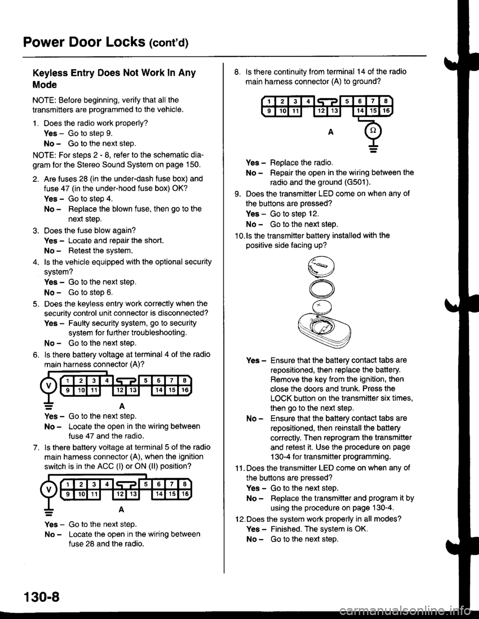
6. ls there battery voltage at terminal 4 of the radio
main harness connector (A)?
7.
=A
Yes - Go to the nen step.
No - Locate the open in the wiring between
tuse 47 and the radio.
ls there battery voltage at terminal 5 of the radio
main harness connector (A), when the ignition
switch is in the ACC (l) or ON (ll) position?
Yes - Go to the next step.
No - Locate the open in the wiring between
fuse 28 and the radio.
130-8
8. ls there continuity from terminal 14 of the radio
main harness connector (A) to ground?
Yes - Replace the radio.
No - Repair the open in the wiring between the
radio and the ground (G501).
9. Does the transmitter LED come on when any ot
the buttons are oressed?
Yes - Go to steo 12.
No - Go to the next steo.'10.ls the transmitter battery installed with the
positive side facing up?
Yes - Ensure that the battery contact tabs are
repositioned, then replace the battery.
Remove the key from the ignition, then
close the doors and trunk. Press the
LOCK button on the transmitter six times,
then go to the next step.
No - Ensure that the baftery contact tabs are
repositioned, then reinstall the batlery
correctly. Then reprogram the transmitter
and retest it. Use the procedure on page
1 30-4 f or transmitter programming.
11 . Does the transmitter LED come on when any of
the buttons are oressed?
Yes - Go to the next step.
No - Replace the transmitter and program it by
using the procedure on page 130-4.
12.Does the system work properly in all modes?
Yes - Finished. The system is OK.
No - Go to the next steD.