1999 HONDA CIVIC Synchro ring
[x] Cancel search: Synchro ringPage 53 of 2189

Standards and Service Limits
Manual Transmission S40 - Section 13
MEASUREMENT
Capacity | (US qt, tmp qt)
End playDiameter of ball bearing contact area A(Transmission housing side)Diameter of 4th, 5th gear contact area BDiameter of 3rd gear contact area CDiameter of ball bearing contact area D(Clutch housing side)Bunout
STANDARD INEW}'1.9 (2.0, 1.7)for overhaul1.8 (1.9, 1.6) for oitchange
0.11 0.18 (0.004 _ 0.007)21.987 - 22.000 (0.8656 0.8661)
26.980 26.993 (1.0622 _ 1.0627)33.984 34.000 (1.3380 1.3386)25.917 - 25.99011.0227 1.0232)
0.02 (0.001) max.
SEBVICE LIMIT
ro
MainshaftAdjust21.930 (0.8634)
26.930 ('1.0602i33.930 (1.3358)
25.92011.0205)
0.05 (0.002)
39.07 ('r.538)
0.33 {0.013)0.31 (0.012)
30.15 (1.187)
30.05 (1.183)
37.07 {1.459)0.31 (0.0'12)
28.35 (1.116)
LrO
39.009 39.025 (1.5358 1.5364)0.06 0.21 (0.002 0.008)0.06 0.19 (0.002 0.007)30.22 30.21 (1.190 1.192)30.12 - 30.17 (1.186 1.188)
37.009 37.025 (1.4570 _ 1.4577)0.06 - 0.19 (0.002 - 0.007)28.42 - 2a.47 11.119,1.1211Countershaft Diameter of needle bearing contact area ADjameter of lst gear contact area gDiameter of ball bearing contact area CRunout
30.000- 30.015 {1.181 1 - 1.1817)35.984 - 36.000 (1.4167 1.4173)24.980 24.993 (0.9835 - 0.9840)0.02 (0.001)max.
29.950 (1.1791)3s.930 r.4146)24.930 (0.9815)0.0s (0.002)
End play (When tightened by the specified torque)Thickness
41.009 - 41.025 ('�t.6145 1.6152)0.03 0.10 (0.001 _ 0.004)30.41 30.44 (1.197 - 1 198)
41 .01 11.617J0.22 (0.009)
30.36 (1.195)
gear End ptay (When tightened by the specified torque)44.009 - 44.025 (1.7326 1.7333)0.04 - 0.12 (0.002 - 0 005)31.91 31.96 (1.256 1.258)
44.01 11.t35)0.24 (0.009)
31.85 (1.2s4)
33.04 {1.301)38.93 (1.533)32.01 (1.260)
27.06 (1.065)
33.93 (1.336)
3r.93 {1.257)22.81 (0.898)
23.51 (0.926)
15.08 (0.594)
0.14 (0.006)
0.4 (0.016)
0.16 (0.006)
o.6210.0244112.78 (0.5031)
t.D.o. D.Length
33.000 - 33.010 (1.2992 1.2996)38.989 39.000 11.53s0_ 1.53s4)32.03 - 32.06 tl.261 - 1.2621Spacer collar(Mainshaft 4thand 5th gear)
Beverse rdler gear LD.Gear to reverse gear shaft cjearance
27.002 27.012 (1.0631 _ 1.0635)33.989 - 34.000 (1.3381 - 1.3386)3r.989 - 32.000 (1.2594 1.2598)22.83 - 22.86 (0.899 0.900)23.53 23.56 (0.926 - 0.928)
rs.016 15.043 (0.5912 _ 0.5922)0.032 0.077 (0.0013 _ 0.0030)Ring-to gear clearance {Ring pushed against gear)0.73 - 1.l8 (0 029 - 0.046)Fork finger thickness
Fork to-synchro sleeve clearance
lsv2nd/sth I 6.2 - 6.410.244 - O.ZS2)3rdl4th 7.4 i.6lO 2g1 O 2ggt0.35 - 0.65 (0.014 - 0.026)Beverse shitt fork Fork pawl groove widthFork to-reverse idler gear clearanceL groove widthFork'to-5th/reverse shift piece pin clearance
12.7 - 13.0 (0.50 _ 0.51)0.5 1. t (0.020 0.043)7 .05 - 7 .25 tO.21A - 0.28510.05 0.35 (0.002 0.014)Sh ift a rm A tnner diameter of sh ift arm C contact ffiShift arr14-go "L;L ".m C clearance13.05 13.13 (0.514 0.517)0.05 - 0.23 (0.002 _ 0.009)Inner diameter of shift arm B shaft contact pointShift arm 8-to shaft clearanceShift arm B to-shift piece clearanceDiameter of shift piece contact point
13.973 - 14.000 (0.5501 0.5512)0.013 0.070 (0.0005 _ 0.0028)0.2 - 0.5 {0.008 0.020)12.9 13.0 (0.508 - 0.512)MBS Shift prece Diameter of pin6.9 7 .1 \O.27 0 2A)
0.095 (0.004)
0.14 (0.006)
Adjust with shim
Differenlial carrier Pinion shaft bore diameterCarrier-to pinion shaft clearanceDriveshaft bore diameterCarrier to,driveshaft clearance
18.010 18.028 (0.7091 _ 0.7098)0.023 0.057 (0.0009 - 0.0022)26.025 26.04s {1.0246_ 1.0254)0.045 - 0.086 (0.0018 0.0034)BacklashPinion gear bore diameterPinion gear-to pinion shaft clearance
0.05 0.15 (0.002 0.006)18.042 - 18.066 (0.7103 _ 0.7113)0.055 - 0.095 {0.0021 _ o.oo37)
0 0.1 10 - 0.004)
3-8
LO
Page 55 of 2189
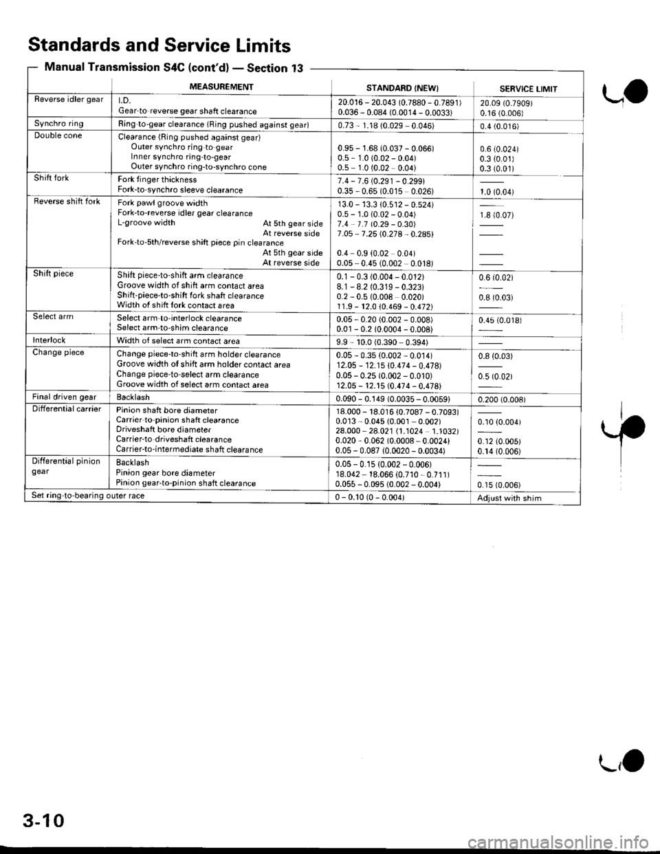
MEASUREMENTSTANDARD (NEW) SERVICE LIMITReverse idler geart.D.Gear-to reverse gear shaft clearance20.016 - 20.043 (0.7880 -0.7891)
0.036 - 0.084 {0.0014 - 0.0033)20.09 (0.7909)
0.16 (0.006)
Synchro ringRing to-gear clearance (Ring pushed against gear)0.73 - 1.18 (0.029 0.046)0.4 (0.016)Double coneClearance (Ring pushed against geadOuter synchro ring to gearIn ner synchro ring to-gearOuter synchro ring-to-synchro cone
0.9s - 1.68 10.037 - 0.066)0.5 - 1.0 (0.02 - 0.04)0.5 1.0 (0.02 - 0.04)
0.6 (0.024)
0.3 {0.01)0.3 (0.01)Shift forkFork {inger thicknessFork-to synchro sleeve clearance7.4 - 7.6 (0.291- 0.299i0.35 - 0.65 (0.015 0.026)1.0 (0.04)Beverse shift forkFork pawl groove widthFork-to-reverse idler gear clearanceL-groove width At 5th gear sideAt reverse sideFork'to-5th/reverse shift piece pin clearanceAt 5th gear sideAt reverse side
13.0 - 13.3 10.512 - 0.524)0.5 - 1.0 (0.02 - 0.04)7.4 t.1 10.29 -O.30)
7 .O5 - 7 .25 (0.21A - 0.2A5i'
0.4 0.9 (0.02 0.04)0.05 0.45 (0.002 - 0.018)
1€ {0.07)
Shift pieceShift piece-to-shift arm clearanceGroove width of shift arm contact areaShilt'piece-to-shift fork shaft clearanceWidth of shift lork contact area
0.1 - 0.3 (0.004 - 0.012)8.1-8.2 (0.319 - 0.323i0.2 - 0.5 (0.008 0.020)1 1.9 - 12.0 10.469 - 0.472)
0.6 (0.02)
0.8 (0.03)
Select armSelect arm-to-interlock clearanceSelect arm to-shim clearance0.05 - 0.20 (0.002 - 0.008)0.01 - 0.2 10.0004 - 0.008)0.45 (0.018)
InterlockWidth of select arm contact area9.9 - 10.0 (0.390 0.394)Change pieceChange piece-to-shilt arm holder clearanceGroove width ot shitt arm holder contact areaChange piece-to select arm clearanceGroove width of select arm contact area
0.05 - 0.35 (0.002 - 0.014)12.05 - 12.15 \0.474 -0.47a1
0.05 - 0.25 (0.002 - 0.010)12.05 - 12. t5 (0.474 - 0.478)
0.8 {0.03)
0.5 (0.02)
Final driven gearBacklash0.090 - 0.149 (0.0035 - 0.0059)0.200 (0.008)DifferentialcarrierPinion shatt bore diameterCarrier to-pinion shaft clearanceDriveshaft bore diameterCarrier-to driveshaft clearanceCarrier-to-int6rmediate shatt clearance
18.000 - 18.016 10.7087 - 0.7093)0.013 - 0.045 {0.001 0.002)24.000 - 28.021 11.1024 1.1032)0.020,0.062 (0.0008 - 0.0024)0.05 - 0.087 {0.0020 - 0.0034)
0.10 {0.004)
0.12 (0.005)
0.14 (0.006)
Differential piniongearBacklashPinion gear bore diameterPinion gear-to-pinion shaft clearance
0.05 -0.15 (0.002 - 0.006)18.042 18.066 (0.710 - 0.711)0.055 - 0.095 (0.002 - 0.004)0.15 (0.006)
Set ring to bearing outer race0 - 0.10 (0 - 0.004)Adjust with shim
Standards and
Manual Transmission
Service
S4C (cont'd)
Limits
- Section 13
ua
.'1'
3-10
L,O
Page 66 of 2189
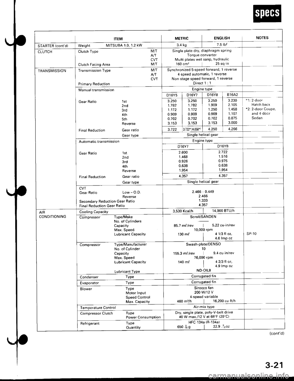
trEM I merntc ENGLISH NorEs
SfAnff n i*nt-i- W"'gf,t MllSUBA r.u, l.z kw r'4 rg
CLUTCHClutch Type
Clutch Facing Area
M/T
CVTM/T
Single plate dry, diaphragm springTorque converterMulti plates wet sanP, hYdraulic160 cm,25 sq in
Synchronized 5-speed forward, 1 reverse
4 speed automatic, 1 reverse
Non stage speed forward, 1 reverse
Direct 1 : 1
TRANSMISSIONTransmission Type
Primary Reduction
M/TArrCW
Manualtransmission
Gear Ratio 1st2nd3rd4th5thReverse
Final Reduction Gear ratio
Gear tYPe
Engine type
D16Y5 | D16Y7 D16Y8 I 81642
3.2501.1821.1120.9090.7023.153
3.2501.1821.1120.9090.7023.153
3.2501.9091.2500.9090.1023.153
3.2302.1051.4581.1070.8753.000
*1:2 doorHatch back+2r 2-door Coupe,and 4 doorSedan
3.122 13.122"11.053" 1 4.250 | 4.266
Single helicalgear
Engine type
D16Y7 | D16Y8Automatic transmission
Gear Ratio 'lst
2nd3rd4thReverse
Final Reduction Gear ratio
Gear tYPe
2.6001.4680.9260.6381.954
2.122
0.9750.6381.954
1.3514.357
cwGear Ratio Low - O.D.Reverse
Secondary Reduction Gear Ratio
Final Reduction Gear Ratio
2.466 0.4492.4661.3334.357
AIRCONDITIONING
Cooling Capacity3,530 Kcal/h14,000 BTU/h
Compressor Type/MakeNo. of CYlindersCaPacitYMax. SpeedLubricant CaPacitY
Scroll/SANDEN
85.7 m//rev 5.22 cu inkev10,000 rpm130 mf 41l3tl oz.
| 4.6 imp ozsP,10
Compressor Type/ManufacturerNo. of CylinderCapacityMax. SpeedLubricant CaPacitY
Lubricant TYPe
Swash-plate/DENso10155.3 mf /rev 9.4 cu_in/rev76,000 rpm140 mf | 4 2l3fl oz,I 4 9lmp ozND'OIL8
Condenser TypeCorrugated fin
Evaporator TyPeCorrugated fin
Elower TyPeMotor InputSPeed ControlMax. CaPacity
Sirocco fan200w112v4 speed variable460 m3/h 16,200 cu ft/h
Temperature Control
Compressor Clutch TyPePower ConsumPtionDry, single plate, PolY-V'belt drive40 W max./12 V at 68'F (20'C)
Refrigerant TyPeouantity
HFC 134a (R'134a)
650 gos | 22.9 isoz
(cont'd )
4 . J-Z I
Page 120 of 2189
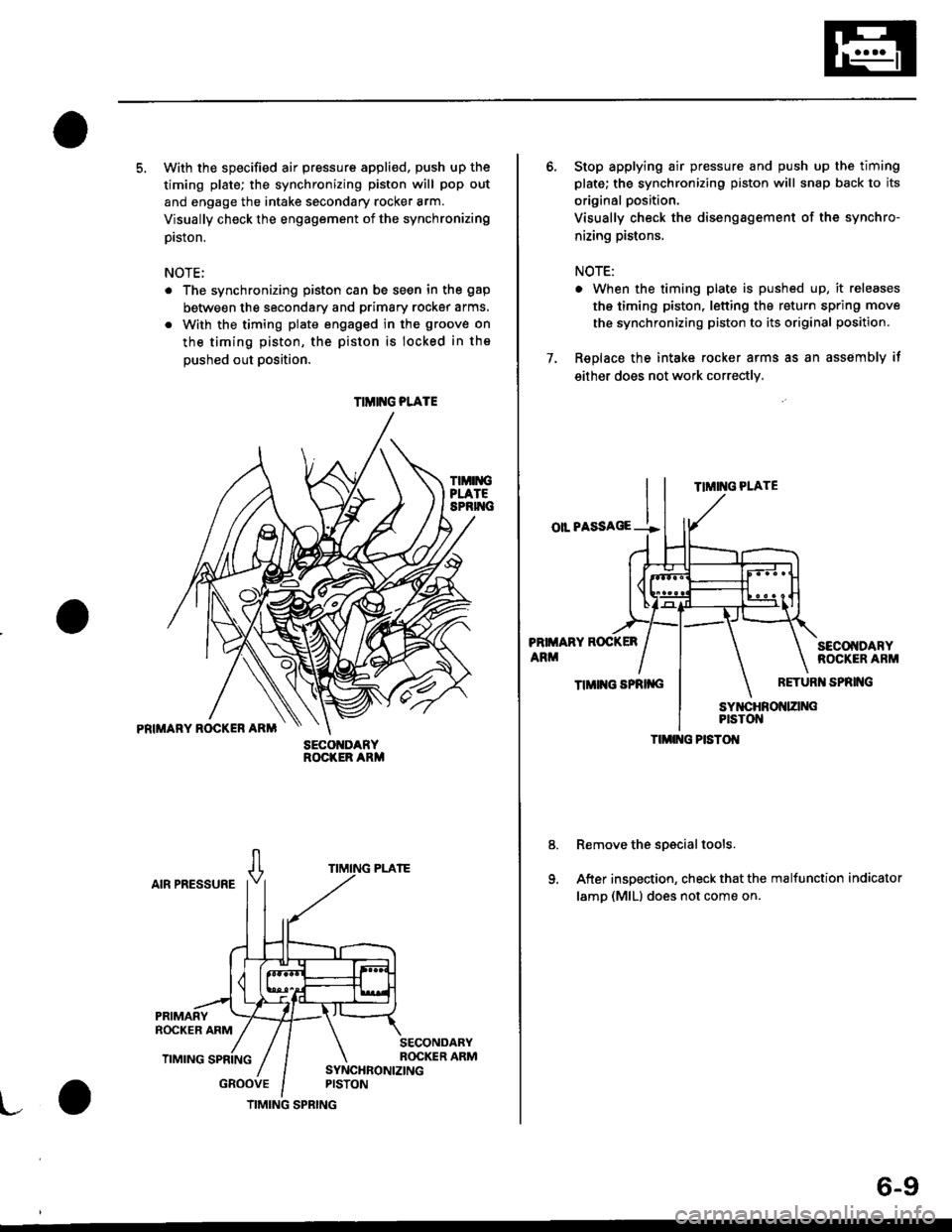
5. With the specified air pressure appli€d, push up the
timing plate; the synchronizing piston will pop out
and engage the intake secondary rocker arm.
Visually check the engagement of the synchronizing
prston.
NOTE;
The synchronizing piston can be seen in the gap
between the secondary and primary rocker arms,
With the timing plate engaged in the groove on
the timing piston, the piston is locked in the
oushed out Dosition.
TIMIiIGPLATESPRIT{C
PRIMARY ROCKER ARM
AIR PRESSURE
GROOVE
SECO DARYROCKER ARM
TIMIT{G PLATE
TIMING SPRING
6-9
6. Stop applying air pressure and push up the timing
plate; the synchronizing piston will snap back to its
original position.
Visually check the disengagement of the synchro-
nizing pistons.
NOTE:
. When the timing plate is pushed up, it releases
the timing piston, letting the return spring move
the synchronizing piston to its original position.
7. Replace the intake rocker arms as an assembly if
either does not work correctly,
TIMING PLATE
oll PASSAGE --!
PRIMARY ROCKER
ARMSECOI{DARYROCKER ARM
TIMII{G SPRII{GRETURI{ SPRING
Remove the spscial tools.
After inspection, check that the malfunction indicator
lamp (MlLl does not come on.
TIMI G PISTOI{
Page 145 of 2189

Rocker Arms and Lost Motion Assemblies
Inspection (D16Y5, Dt6Y8 enginesl
NOTEr When reassembling the primary rocker arm,carefully apply air pressure to the oil passage of therocker arm.
1. Inspect the rocker arm piston. push it manually.- lf it does not move smoothly, replace the rockerarm assembty.
Dl6Y5 engine:
ROCKER ARM
TIMING PISTON
TIMING SPRING
SYNCHRONTZINGPISTON
SECONDARYROCKER ARM
MID ROCKER ARM
PRIMARY ROCKER
SYNCHRONIZINGPISTON A
NOTE:
. Apply oil to the pistons when reassembling.o Bundle the rocker arms with a rubber band to preventthem from separating.
6-34
(\
DI6YS engine:
NOTE: Set the timing plate and return spring as shownoerow.
RETURN
CAMSHAFT HOLDER
Dl6Yg engine:
2. Remove the lost motion assembly from the holderand inspect it. Test it by pushing the plunger withyour finger.- lf the lost motion assembly plunger does notmove smoothly, replace it.
LOST MOTION ASSEMBLY
\a
Pu3h
I
Page 581 of 2189
\
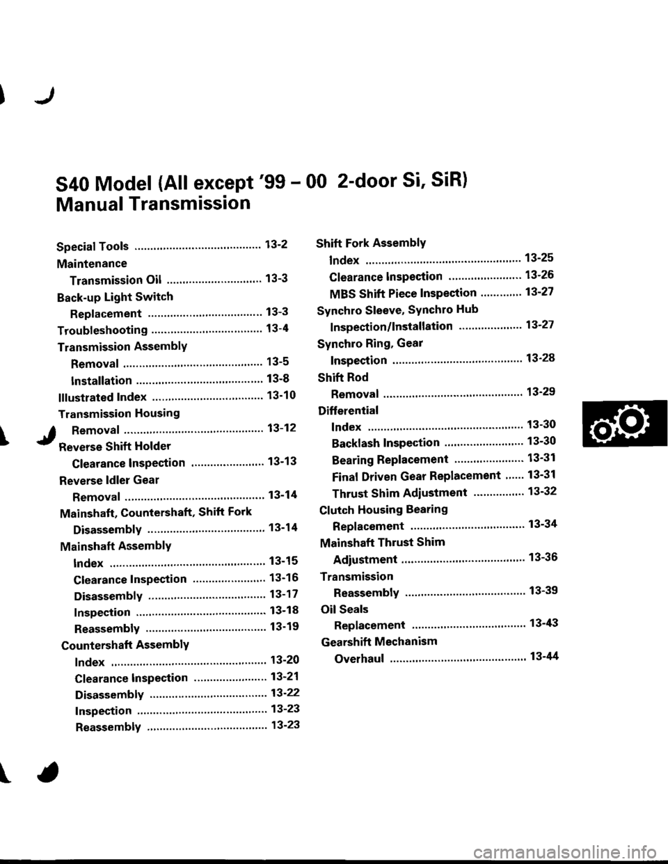
S40 Model (All except'99 - 00 2-door Si' SiR)
Manual Transmission
Special Tools ..'.......... 13-2
Maintenance
Transmission Oil .............................. 13-3
Back-up Light Switch
Replacement ......... 13-3
Troubleshooting '....... 13-4
Transmission AssemblY
Removal ................. 13-5
lnstallation ............. 13-8
lllustrated Index ...............'........."........ 13-10
Transmission Housing
I Removaf .."""""""' 13-12
J R"rr"r"" Shift Holder
Clearance lnspection ....................... 13-13
Reverse ldler Gear
Removal ....'.........." 13-14
Mainshaft, Countershaft, Shift Fork
Disassembly ......'... 13-14
Mainshaft AcsemblY
Index ............... ....... 13-15
Clearance Inspection ..'.................... 13-16
Disassembly .......... 13-17
Inspection ....'......... 13-18
Reassembly ........... 13-19
Countershaft AssemblY
lndex ................ ...... 13-20
Clearance lnspection ."..........'......." 13-21
Disassembly ..."""' 13-22
Inspection .............. 13-23
Reassembly ..'.""... 13-23
Shift Fork AssemblY
lndex ............... ."'... 13-25
Clearance lnspection ."......."........'.. 13'26
MBS Shift Piece Inspection ....-.....'.. 13'27
Synchro Sleeve, Synchro Hub
f nspection/lnstallation .......'...... ".... 13'27
Synchro Ring, Gear
Inspection '....'..".... 13'28
Shift Rod
Removal .'......".""" 13'29
Differential
lndex ......."'...... .'."' 13-30
Backlash Inspection ..........."......."... 13-30
Bearing Beplacement'.............'.".... 13'31
Final Driven Gear Replacement '..... 13-31
Thrust Shim Adiustment ..."........... 13-32
Clutch Housing Bearing
Replacement .......'. 13-34
Mainshaft Thrust Shim
Adiustment '....'..".. 13-36
Transmission
Reassembly ........... 13-39
Oil Seals
Replacement ......... 13-43
Gearshift Mechanism
Overhaul ................ 13-44
\
Page 584 of 2189
Troubleshooting
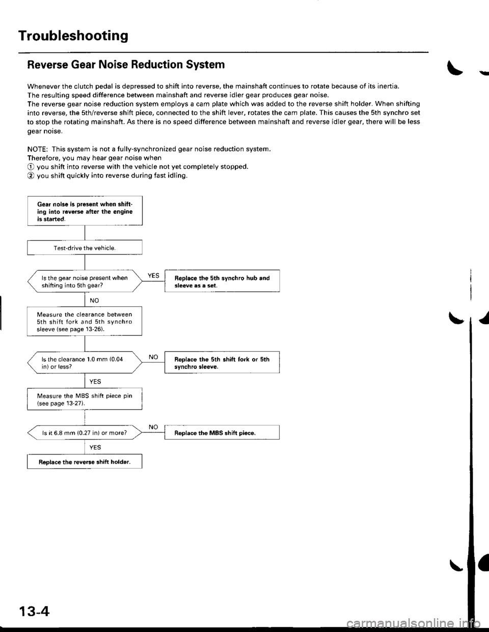
Reverse Gear Noise Reduction System
Whenever the clutch pedal is depressed to shift into reverse, the mainshaft continues to rotate because of its inertia.
The resulting speed difference between mainshaft and reverse idler gear produces gear noise.
The reverse gear noise reduction system employs a cam plate which was added to the reverse shift holder. When shifting
into reverse, the sth/reverse shjft piece, connected to the shift lever, rotates the cam plate. This causes the sth synchro set
to stop the rotating mainshaft. As there is no speed difference between mainshaft and reverse idler gear, there will be less
gear norse.
NOTE: This system is not a fully-synchronized gear noise reduction system.
Therefore, you may hear gear noise when
O you shift into reverse with the vehicle not yet completely stopped.
@ you shift quickly into reverse during fast idling.
-
Gear noise is oresent when shift-ing into reverce after the engineis started.
Test-drive the vehicle.
ls the gear noise present whenshifting into 5th gear?Beplace the 5th synchro hub and3leeve e3 a set,
Measure the clearance between5th shift fork and 5th synchrosleeve {see page 13'26).
ls the clearance 1.0 mm (0.04
in) or less?
Measure the MBS shift piece pin(see page 13-27).
ls ( 6.8 mm (0.27 in) or more?Replace the MBS shift piece.
ReDlace the reve6e ahift hold.r.
13-4
Page 591 of 2189
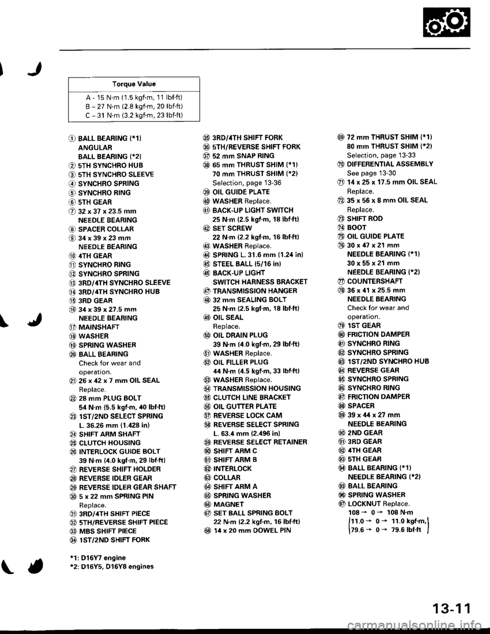
Torque Value
A - 15 N.m (1.5 kgf.m, 1'1 lbf.ft)
B - 27 N.m (2.8 kgf.m. 20 lbift)
C - 31 N.m {3.2 kgnm, 23 lbift)
\
O BALL BEARING (*T)
ANGULAR
BALL BEARING {*2I
O 5TH SYNCHRO HUB
O 5TH SYNCHRO SLEEVE
€) SYNCHRO SPRING
o SYNCHRO B|NG
@ 5TH GEAR
@ gz xgt x 23.5 mm
NEEDLE BEARING
@ SPACER COLLAR
@34x39x23mm
NEEDLE BEARING
(D 4TH GEAR
O SYNCHRO RING
C) SYNCHRO SPRING
CO 3RD/4TH SYNCHRO SLEEVE
@ 3RD/4TH SYNCHRO HUB
(} 3RD GEAR
@34x39x27.5mmNEEDLE BEARING
G) MAINSHAFT
G) WASHER
@ SPRING WASHER
@ BALL BEARING
Check for wear and
operation.(E 26x42x7 mm OIL SEAL
Replace.
@ 28 mm PLUG BOLT
5,1 N.m {5.5 kgf'm, /t0 lbt'ft)
@ lsT/zND SELECT SPRING
L. 36.26 mm (1./P8 in)
@ SHIFT ARM SHAFT
@ CLUTCH HOUSING
@ INTEELOCK GUIDE BOLT
39 N.m (4.0 kgf.m, 29 lbf.ftl
@ REVERSE SHIFT HOLDER
@ REVERSE IDLER GEAR
@ REVERSE IDLER GEAR SHAFT
@ 5 x 22 mm SPRING PIN
Replace.
@ 3RD/4TH SHIFT PIECE
@ 5TH/REVERSE SHIFT PIECE
@ MBS SHIFT PIECE
@ 1ST/2ND SHIFI FORK
*1:D16Y7 engine*2: D16Y5, D16Y8 engines
@ 3RD//|TH SHIFT FORK
@ 5TH/REVERSE SHIFT FORK
@ 52 mm SNAP RING
@ 65 mm THRUST SHIM (*11
70 mm THRUST SHIM (*21
Selection, page 13-36
@ OIL GUIDE PLATE
@ wASHER Replace.
@ BACK.UP LIGHT SWITCH
25 N.m (2.5 kgf'm, 18 lbf'ft)
@ sET SCREW
22 N.m {2.2 kgf.m, 16 lbl.ft}
@ WASHER Replace.
@D SPRING 1.31.6 mm (1.2,1inl
@ STEEL BALL 15/16 in)
@ BACK-UP LIGHT
SWITCH HARNESS BRACKET
@ TRANSMISSION HANGER
@ 32 MM SEALING BOLT
25 N.m (2.5 kgf.m, 18 lbt'ft)
@ OIL SEAL
Replace.
@ OIL DRAIN PLUG
39 N.m (4.0 kgf.m, 29 lbf.ft)
@ WASHER Replace.
@} OIL FILLER PLUG
44 N.m (4.5 kgf.m, 33 lbf'ftl
@ WASHER Replace.
@) TRANSMISSION HOUSING
€) CLUTCH LINE BRACKET
@ OIL GUTTER PLATE
@ REVERSE LOCK CAM
@ REVEBSE SELECT SPRING
L. 63.4 mm {2.,196 in)
@ REVERSE SELECT RETAINER
@ SHIFT ARM C
@ SHIFT ARM B
@ INTERLoCK
@ COLLAR
@ SHIFT ARM A
@ SPRING WASHER
@ MAGNET
@ sET BALL SPRING BOLT
22 N.m (2.2 kgf.m, 16 lbf.ftl
@ 14 x 20 mm DOWEL PIN
@ 72 mm THRUST SHIM l*11
80 mm THRUST SHIM (*21
Selection, page '13-33
@ DIFFERENTIAL ASSEMBLY
See page 13-30
@ 14 x 25 x 17.5 mm OIL SEAL
Replace.
@ 35 x 56 x 8 mm OIL SEAL
Replace.
@ SHIFT ROD
@ BOOr
@ OIL GUIDE PLATE
@30x47x21 mm
NEEDLE BEARING (* 1}
30x55x21 mm
NEEDLE BEARING {'2)
@ COUNTERSHAFT
@36x41 x 25.5 mm
NEEDLE BEARING
Check for wear and
operatron.
@ lsT GEAR
@ FRICTION DAMPER
@ SYNCHRO RING
@ SYNCHRO SPRTNG
@ lST/2ND SYNCHRO HUB
@ REVERSE GEAR
@ SYNCHRO SPRING
@ SYNCHRO RING
@ FRICTION DAMPER
@ SPACER
@39x4lx27mm
NEEDLE BEARING
@ 2ND GEAR
@ 3RD GEAR
@ 4TH GEAR
@ sTH GEAR
@) BALL BEARING {* 1}
NEEDLE BEARING (*2}
@ BALL BEARING
@) SPRING WASHER
@ LoCKNUT Replace.
108 - 0- 108 N.m
ftt.o* o- 1r.o kst.m,l
179.6- 0- 79.6 rbtft I
13-1 1