Page 660 of 2189
Synchro Sleeve, Synchro Hub
Inspection
1,Inspect gear teeth on all synchro hubs and synchro
sleeves for rounded off corners. which indicates
Install each synchro hub in its mating synchro
sleeve and check for freedom of movement.
NOTE: lf replacement is required, always replace
the synchro sleeve and synchro hub as a set.
Installation
When assembling the synchro sleeve and synchro hub,
be sure to match the three sets of longer teeth (120
degrees apart) on the synchro sleeve with the three sets
of deeper grooves in the synchro hub.
CAUTION: Do noi install tho synchro sleeve with its
longer toeth in the synchro hub slots, because it will
damage the spring ring.
SYNCItROSLEEVCLONGER TEETH
13-80
Page 661 of 2189

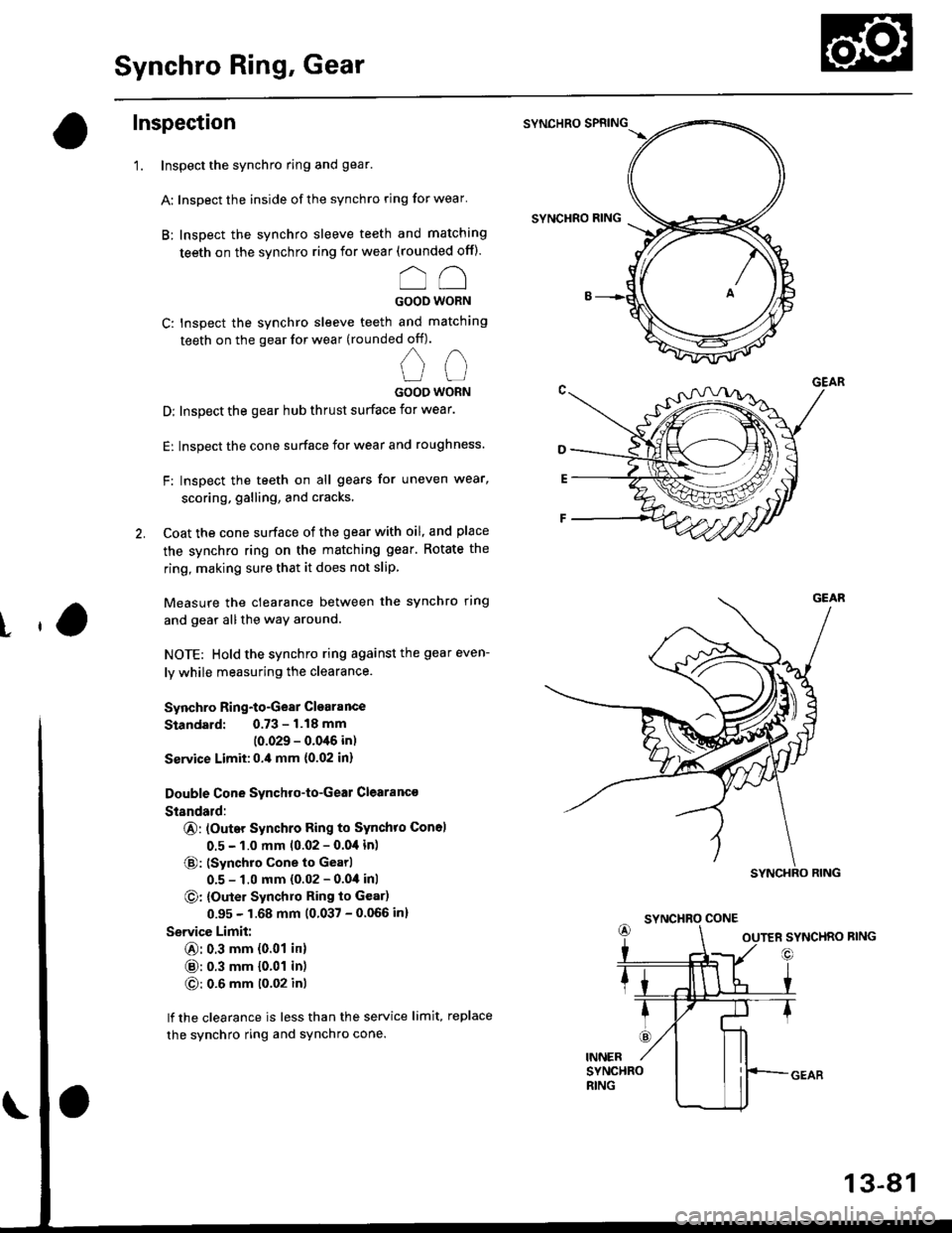
Synchro Ring, Gear
Inspection
'1. Inspect the synchro ring and gear.
A: Inspect the inside of the synchro ring for wear'
B: Inspect the synchro sleeve teeth and matching
teeth on the synchro ring for wear (rounded off).
oo
GOOD WORN
C: Inspect the synchro sleeve teeth and matching
teeth on the gear for wear (rounded off).
nn
UUGOOO WORN
D: Inspect the gear hub thrust surface for wear.
E: Inspect the cone surface for wear and roughness.
F: Inspect the teeth on all gears for uneven wear,
scoring, galling, and cracks'
2. Coat the cone surface of the gear with oil, and place
the synchro ring on the matching gear. Rotate the
ring, making sure that it does not slip
Measure the clearance between the synchro ring
and gear allthe way around.
NOTE: Hold the synchro ring against the gear even-
ly while measuring the clearance.
Synchro Ring-to-Gear Clearance
Standard: 0.73 - 1.18 mm
(0.029 - 0.0'16 in)
Ssrvice Limit:0.,0 mm {0.02 in}
Double Cone Synchro-to-Geal Clearanc€
Standald:
@: (Outer Synchro Ring to Synchro Con6l
0.5 - 1.0 mm 10.02 - 0.04 in)
@: (Synchro cone to Gearl
0.5 - 1.0 mm (0.02 - 0.04 inl
O: {Outer Synchlo Ring to Gear)
0.95 - 1.68 mm (0.037 - 0.066 in)
Service Limit:
@: 0.3 mm {0.01 in}
@: 0.3 mm {0.01 in)
O: 0.6 mm t0'02 inl
lf the clearance is less than the service limit, replace
the synchro ring and sYnchro cone.
SYNCHRO SPRING
SYNCHRO RING
t
SYNCHRO CONE
13-81
Page 668 of 2189

Mainshaft Thrust Clearance
Adjustment
1. Remove the 72 mm thrust shim and oil guide platefrom the transmission housing.
4.
TFANSMISSIONHOUSING
72 mm THRUST SH|M
TRAt{SMtSStONHOUSINGOIL GUIOE PLATE
lnstall the 3rd/4th synchro hub. spacer collar,5thsynchro hub. spacer, and ball bearing on the main_shaft, then install the above assembly in the trans_mission housing.
lnstall the washe[ on the mainshaft,
Measure distance @ between the end of the trans-mission housing and washer.
NOTE;
. Use a straight edge and vernier caliper.. Measure at three locations and average the read_ing.ENO otlnA sMtsstoNHOUSINGMAINSHAFT
3RD/irTH SYNCHRO HUB
SPACCR COLLAR
5TH SYNCHRO HUB
o
B
13-88
AALL BEARING
V.
5. Measure distance @ between the end of the clutchhousing and bearing inner race.
NOTE;
. Use a straight edge and depth gauge.. Measure at three locations and average the read-ings.
Select the prcpet 72 mm thrust shim from the chartby using the formula below.
NOTE: Us€ only one 72 mm thrust sntm.
Shim Selection Formula:
From the measurements you made in steps 4 and 5:. Add distance O lstep 5) to distance @ (step 4).
. From this number, subtract 0.93 (which is themidpoint of the flex range of the clutch housingbearing spring washer).
. Take this number and compare it to the availableshim sizes in the chart.
{For example)
B;2.39
+ C: 0.22- 0.93
2.61 = 1.68
Try the 1.68 mm (0.0661 in) shim.
INNER RACE ot EALL BEARING