Page 1387 of 2189
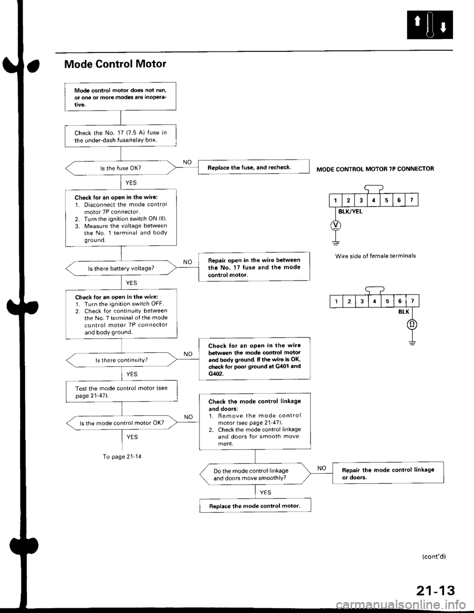
Mode Control Motor
To page 21-14
MODE CONTROL MOTOR 7P CONNECTOR
'1
I2I57
BLK/YEL
Wire side of female terminals
Mode control motor does not run,
or one of more modes are inoPela-
Check the No. '17 (7.5 A) fuse in
the under-dash fuse/relaY box.
Reolace the fuse, and recheck.
Check lor an open in the wire:
1. Disconnect the mode controlmotor 7P connector.2. Turn the ignition switch ON (ll).
3. Measure the voltage betweenthe No. l terminal and bodyg rou nd.
Repair open in the wire between
the No. 17 tuse and the mode
control motor.ls there batterY voltage?
Check {or an open in the wire:1. Turn the ignition switch OFF.
2. Check for continuity between
the No. 7 terminal of the mode
co nlrol motor 7P connector
and body ground.
Check for an open in the wire
batwe€n the mode contrcl motol
and body ground. lf the wir€ is OK,check for poor gtound at G/U)l and
G402.
ls there continuity?
Test the mode control motor (see
page21-471.Check the mod€ control linkage
and doors:1. Bemove the mode controlmotor (see page 21-47).2. Check the mode control linkageand doors for smooth move
ls the mode control motor OK?
Do the mode control linkageand doors move smoothlY?
Reolace the mode control motor,
I34561
BLK
[]
(cont'd)
Page 1390 of 2189
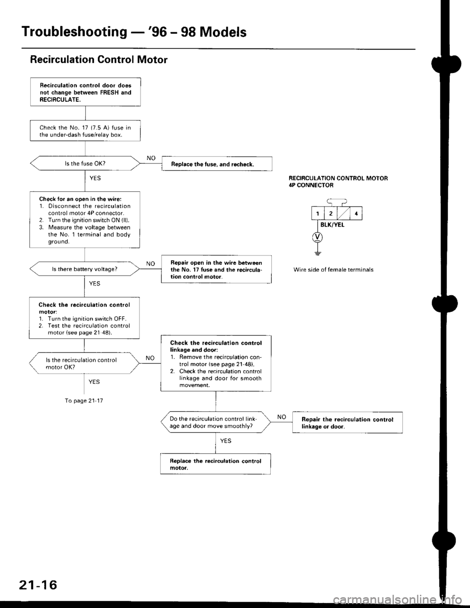
Troubleshooting -'96 - 98 Models
Recirculation Control Motor
Becirculation control door doesnot change between FRESH andRECIBCULATE.
check the No- 17 (7.5 A) fuse inthe under-dash fuse/relay box.
Reolace the tuse. and recheck.
Check for an open in the wire:1. 0isconnect the recirculationcontrol motor 4P connector.2. Tu.n the ignition switch ON (ll).
3. Measure the voltage betweenthe No. l terminal and bodyground.
Repair open in the wir6 betweenthe No. 17Iuse and the recircula-lion conlrol motor.ls there battery voltage?
Check lhe recirculation control
1. Turn the ignition switch OFF.2. Test the recirculation controlmotor {see page 21 48).
Check the recirculation controllinkage and door:1. Remove the recirculation con'trol motor {see page 21 48}.2. Check the recirculation controllinkage and door for smooth
Do the recirculation control linkage and door move smoothly?Reoair the r€circulation controllinkage or door.
RECIRCULATION CONTROL MOTOR4P CONNECTOR
BLK/YEI-
Wire side of temale terminals
Io page 21 17
21-16
Page 1392 of 2189
Troubleshooting -'96 - 98 Models
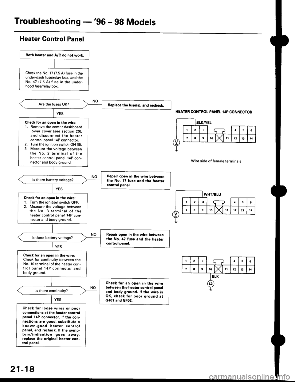
Both heater and A/C do not work.
Check the No. 17 {7.5 A) fuse in theunderdash fuse/relay box, and theNo. 47 (7.5 A) fuse in the underhood fuse/relay box.
R.phce the fuso{s), .nd rccheck.
Chack tor an open in the wi.e:1. Remove the center dashboardlower cover (see section 20),and disconnect the heatercontrol panel 14P connector.2. Torn the ignition switch ON {ll).3. Measure the voltage betweenthe No. 2 terminal of theheater control panel 14P con-nector and body ground.
Rcpair opGn in th€ wiro betwoonthe No. 17 tuse and the hoatclcontrol panel.
ls there baftery voltage?
Check for an opon in the wiro:1. Turn the ignition switch OFF.2. Measure the voitage betweenthe No. 3 terminal of theheater control panel 14P con-nector and body ground.
Rgprii open in th6 wira b€twacnthe No. il7 tui. and the heat.tcont.ol p.nal.
ls there battery voltage?
Check foi an open in the wi.e:Check for continuity between theNo. 10 terminal ot the heater con-trol panel 14P connector andbody ground.
Check lor an opon in tho wireb€{w6on the hoator control oaneland body ground. lI the wirc isOK, check tor poor ground atG401 .nd G4O2.
Check for looae wiaos or ooolconnections at the hoater controlpanol 14P connector. lf the con-nactions dre good. 3ubstitute tknown-9ood heater controlpanel, and rech6ck. It tho symp-tom/indication 9oe3 .wry,replace the original heatel con-trol oanol.
Heater Control Panel
HEATER CONTROL PANEL 1,lP CONNECTOR
Wire side of female terminals
21-18
Page 1394 of 2189
Troubleshooting -'99 - 00 Models
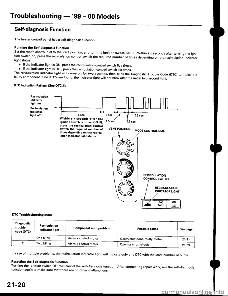
Self-diagnosis Function
The heater control panel has a self-diagnosis function.
Running the Self-diagnosis Funqtion
Set the mode control dial to the Vent position, and turn the ignition switch ON fll). Within six seconds after turnang the igni_tion switch on. press the recirculation control switch the required number of times depending on the recirculation indicatorlight status:
.lftheindicatorlightisON,presstherecirculationcontrolswitchfivetrmes.
.lftheindicatorlightisOFF,presstherecirculationcontrol switch six rrmes.The recirculation indicator light will come on for two seconds. then blink the Diagnostic Trouble code {DTc} to indicate afaulty component. lf no DTc's are found, the indicator light will not blink after the initial two second liqht.
DTC Indication Pattern (S6e DTC 2l:
Recirculationindicato.light on
Recirculationindicatorlight off2 sec
,/1.5 soct
' 0,3 secWithin six seconds atter theignition switch is turned ON (lll,pross the recirculation controlswitch the required number ottimes depending on the rocircu-lation indicetor light status
0.3 sec
VENT POSITIONMODE CONTROL DIAL
RECIRCULATIONCONTROL SWTCH
DTC Troubleshooting Index
Diagnostic
trouble
code (DTCI
Rgcirculation
indicator lightComponent with problemPossible causeSee page
One blinkAir mix control motorObstructed door, laulty motor21-21
2Two blinksAir mix control motorOpen or short circuit21-23
ln case of multiple problems, the recirculation indicator light will indicate only one DTc with the least number of blinks.
Resetting the Self-diagnosis FunctionTurning the ignition switch OFF will cancel the self-diagnosis function, After completing repair work, run the setf diagnosisfunction again to make sure that there are no other malfunctions.
21-20
@
At
V'
Page 1399 of 2189
![HONDA CIVIC 1999 6.G Workshop Manual Mode control motor does not run.
or one or more modes arc inope]a-
tive.
Check the No. 17 (7.5 A) fuse in
the under-dash fuse/relay box.
Replace the Iuse. and recheck.
Check for an open in the wire:
1 HONDA CIVIC 1999 6.G Workshop Manual Mode control motor does not run.
or one or more modes arc inope]a-
tive.
Check the No. 17 (7.5 A) fuse in
the under-dash fuse/relay box.
Replace the Iuse. and recheck.
Check for an open in the wire:
1](/manual-img/13/6068/w960_6068-1398.png)
Mode control motor does not run.
or one or more modes arc inope]a-
tive.
Check the No. 17 (7.5 A) fuse in
the under-dash fuse/relay box.
Replace the Iuse. and recheck.
Check for an open in the wire:
1. Disconnect the mode control
motor 7P connector,
2. Turn the ignition switch ON (ll)-
3. MeasLrre the voltage between
the No. 1 terminal of themode control motor 7P con
nector and body ground
Repair open in the wire between
the No. 17 luse and lhe mode
control motor.ls there battery voltage?
Check the mode control motor:
1- Turn the ignition switch OFF
2, Test the mode control motor(see page 21 47).Check lhe mode control linkage
and doors:1. Remove the mode controlmotor (see page 21 47).
2. Check the mode control linkage
and doors for smooth move
ls the mode control motor OK?
Do the mode control linkage
and doors move smoothlY?
ReDlace the mode control motor'
Check for a short to Power in the
wires:1. Iurn the,gnitjon switch ON(ll).
2, Disconnect the heater controlpanel20P connector.3. Check for voltage betweenthe No. 2, 5, 6, 7, I and 9 ter'minals of the heater controlpanel 20P connector andbody ground individuallY.Repair shorl to power in the
wire{sl between the heater con-
trol oanel and the mode controlmotor. This short also damagesthe heater control Pan6l. RePair
the short to power before replac'ing the heater control Panel
ls lhere any voltage?
MODE CONTROL MOTOR 7P CONNECTOR
t2315
BLK/YEL
Wire side of female terminals
HEATER CONIROL PANEL 2OP CONNECTOR
Wire side of female terminals
NO
(cont'd)
21-25Io page 21 26
Page 1400 of 2189
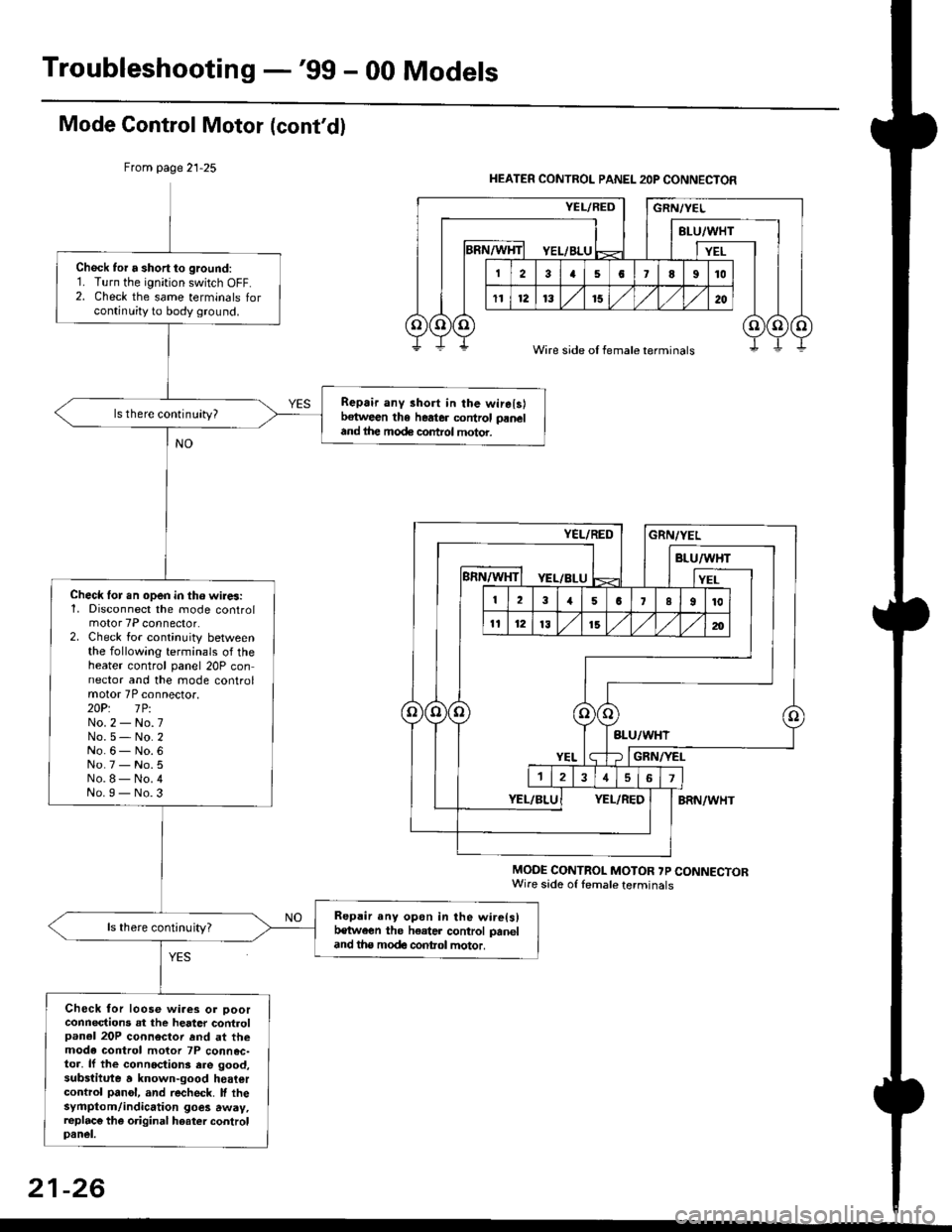
Troubleshooting -'gg - 00 Models
Mode Gontrol Motor (cont'dl
From page 21-25
MODE CONTROL MOTOR ?P CONNECTORWire sade of lemale terminals
Chock tor a short to ground:1. Turn the ignition switch OFF.2. Check the same terminals forcontinuity to body ground.
Repair any 3hort in the wirelslbetween the heater control paneland ihe mode control motor.
ls there continuity?
Check lor.n open in tho wires:1, Disconnect the mode controlmotor 7P connector.2. Check for continuity betweenthe following terminals of theheater control panel 20P connector and the mode controlmotor 7P connector.2OP: lPiNo.2 - No.7No.5- No.2No.6- No.6No.7 - No.5No.8- No.4No.I - No.3
Repair any opon in the wire(s)t€tween the h€ater control paneland tha modc contol motor.
ls there continuity?
Check for loose wiaes or ooorconnections at the heater controlpanel 20P connector rnd at themode control motor 7P connec-toa, lf the connoctions ere good,substitute a known-good heatercontrol panol, and recheck. lf thesyfiptom/indication goes away,replac€ the original hoater controlpanel.
HEATER CONTROL PANEL 2OP CONNECTOR
Wire side of female terminals
21-26
Page 1401 of 2189
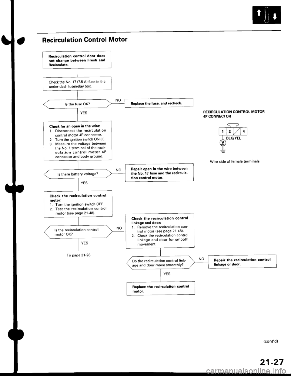
Recirculation control door does
not chango betwe€n Fresh and
Recirculate.
Check the No. l7 (7.5 A) fuse an the
underdash fuse/relay box.
Replace the fuse, and recheck.
Check lor an oPen in the wite:
1. Disconnect the recirculation
control motor 4P connector.
2. Turn the ignition switch ON (ll)
3. Measure the voltage between
the No. 1 terminal of the recir
culation control motor 4P
connector and body ground.
Repair open in the wire between
the No. 17 luse and lhe recircula-
tion control motor.ls there battery voltage?
Check the rccirculation control
motorr']� Turn the ignition switch OFF.
2. Test the recirculation control
motor (see Page 21 48i
Check the recirculation control
linkage and door:1. Remove the recirculation con_
trol motor lsee Page 2l 48).
2. Check the recirculation control
linkage and door for smooth
movement.
Reoair the recirculation conlrol
linkag€ or door.Do the recirculation control link_
age and door move smoothlY?
CONTROL MOTOR
side of temale terminals
RECIRCULATION CONTRC,lP CONNECTOR
q-?--T--T--T-|1l2l/l1l
f BLK/YEt(v)
!
page
(cont'd)
Page 1402 of 2189
Troubleshooting -'99 - 00 Models
Recirculation Control Motor (cont'd)
Frcm page 21-27
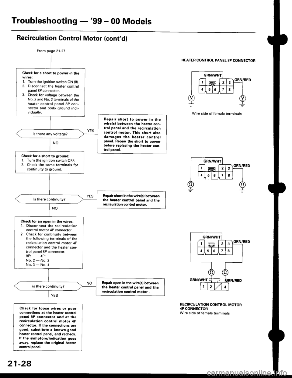
HEATER CONTROL PANEL 8P CONNECTOR
Check for a short to power in the
1. Turn the ignition switch ON {ll).2. Disconnect the heater controlpanel 8P connector.3. Check for voltage between theNo.2 and No. 3 terminals oftheheater control panel 8P con,nector and body ground individually.
Repair 3hort to powe. in thewire{a) b.tween tho haetor con-trol panel and the recirculationGontrol moto.. This short alsodamagos the heate. controlpanel. Repair the short to powerb€tore .eplecing the h€ater con-trol panel.
ls there any voltage?
Check to. a short to ground:1. Turn the ignition switch OFF.2- Check the same terminals forcontinuity to ground.
Roprir lhon in tho wir.{s) b€tweothe horter control panel and theracircr alion conhol motoa.
Check for an open in the wires:1. Disconnect the recirculationcontrol motor 4P connector.2. Check for continuity betweenthe following terminals of therecirculation control motor 4Pconnector and the heater con,trol panel 8P connector.8P: 4PiNo.2 - No.2No.3 - No.4
Repair open in ths wirolsl betw€€nthe heate. co.rkol panol and therecirculation control motor .
Check lor loo3a wires or pootconn€ctions at the hoater controlpanel 8P connector and at theaecirculation control motor ilPconnector, It tho connections aregood. substitut€ e known-goodheatei control panel, and aecheck.lf th€ symptom/indication goesaway, replace the original hedtercontrcl Danel.
GRN/WHT
I1
GRN/RED
RECIRCULATION CONTROL MOTOR4P CONNECTORWire side of female terminals
21-28