Page 380 of 2189

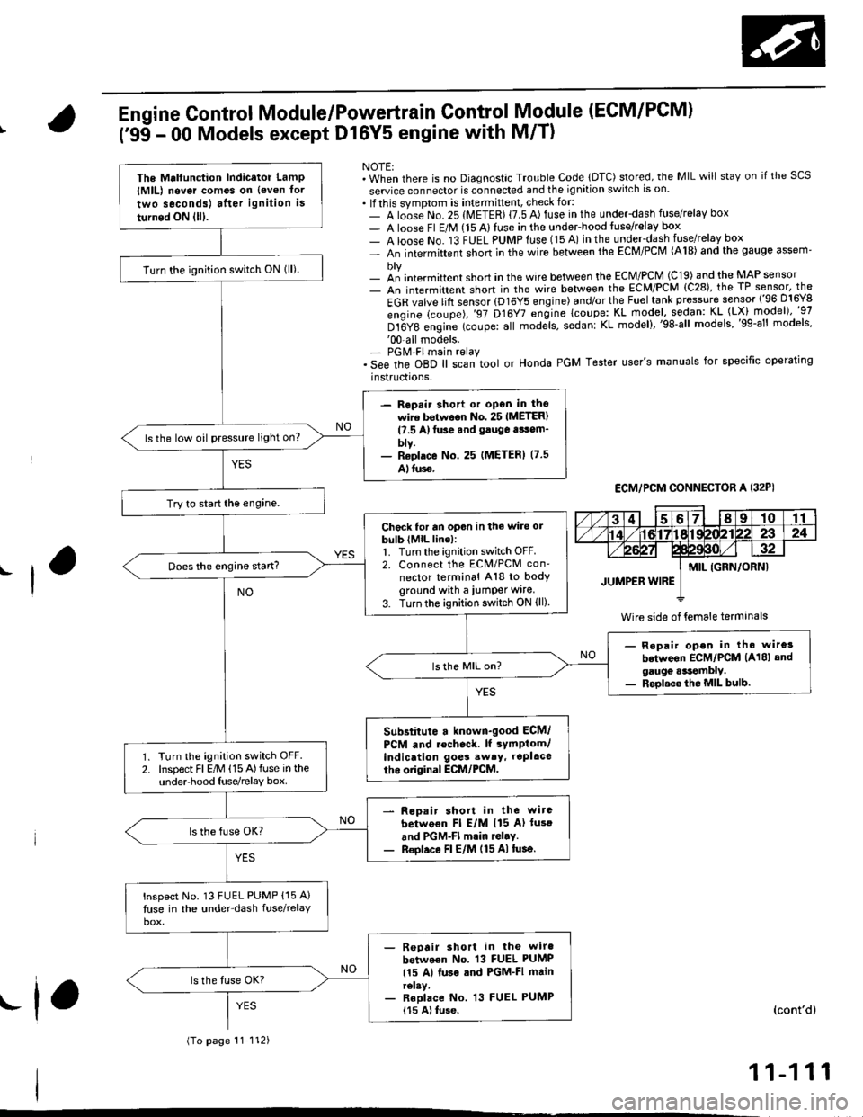
Engine Control Module/Powertrain Control Module (ECM/PCM)
('95 - 00 Models except Dl6Y5 engine with M/T)
NOTE:. When there is no Diagnostic Trouble Code lDTC) stored, the MIL will staY on if the SCS
seruice connector is connected and the ignition switch is on.. lf this symptom is intermittent, check for:- A loose No. 25 (METER) {7.5 A) fuse in the underdash fuse/relay box- A loose Fl E/M (15 Alluse in the undeFhood fuse/relay box- A loose No. 13 FUEL PUMPfuse (15 A) in the under-dash fuse/relay box- An intermittent shon in the wire between the ECM/PCM (A18) and the gauge assem'
- an intermittent short in the wire between the ECM/PCM (C19) and the MAP sensor- An intermittent short in the wire between the ECM/PCM {C28), the TP sensor, the
EGR valve lift sensor (D16Y5 engine) and/or the Fuel tank pressure sensor ('96 D16Y8
engine (coupe),'97 D16Y7 engine lcoupe: KL model, sodan: KL (LX) model)"g7
Dt6Y8 engine (coupe: all mod;ls, sedanl KL model),'98-all models,'99-al' models''00-all models.- PGM'FI main relay. See the oBD ll scan tool or Honda PGM Tester user's manuals for specific operating
instructrons,
ECM,/PCM CONNECTOR A I32PI
Wire side of {emale terminals
The Mrlfunction Indicator LamP{MlL) never comes on {even tor
two seconds) after ignition is
turned ON lll).
Turn the ignition switch ON lll).
- Repair shott or open in thowire bstwoon No. 25 IMETER)l?.5 A)tuse and gauga tsom_blv.- Reolace No. 25 (METERI (7.5
Alluse.
ls the low oil pressure light on?
Try to start the engine.
Check for an opon in the wire orbulb (MlL line):1. Turn the ignition switch OFF.2. Connect the ECM/PCM con'
nector terminal A18 to bodyground with a iumper wire.
3. Turn the ignition switch ON (ll)
Does the engine start?
- Repair open in tho wire3
betwoon ECM/PCM (A18) andgaugo .*tembly.- Rool.ce the MIL bulb.
Substitute a known-good ECM/
PCM and rochoc&. lf sYmptom/indication goes sw6y, repl.ce
tho original ECM/PCM.Turn the ignition switch OFF.Inspect Fl E/M (15 A)fuse in theunderhood Iuse/relay box.
Rop.ir short in the wirc
betwo€n Fl E/M (15 A) luso
and PGM-Fl mrin rGl.y.Reol.ce Fl E/M (15 A)tusa.
lnspect No. 13 FUEL PUMP {15 A}
luse in the under-dash fuse/relay
- Reoair short in the wiro
between No. 13 FUEL PUMP
115 Al luse sod PGM-FI mainrelay.- Reolace No. 13 FUEL PUMP115 A) tuse.
(To page 11 112)
(cont'd)
11-111
.f,
Page 381 of 2189

PGM-FI System
(From page'11-111)
Check loi an open in the wires(lGP linesl:1. Disconnect the lueliniector andIAC valve connectors.2. Turn the ignition switch ON (ll).
3, Measu re voltage betweenbody ground and ECM/PCMconnector terminals 81 andBg individually.
- Repair open in the wiro(3)between ECM/PCM lBl, B9land PGM-Fl main relay.- Check tor poor connectionsor loose wires al the PGM-FImain relav.- Test tho PGM-FI main rehy(3.e page 11-237).
ls there battery voltage?
Check tor an open in the wires(PG, LG lines):1. Reconnect the fuel iniectorand IAC valve connectors.2. Measure voltage betweenbody ground and ECM/PCMconnector terminals 82, 810,820 and 822 individually.
Repair open in the wirels)between ECM/PCM and G 101llocated ai the l6ft side of thointaks m.nifoldl thrt h.d morethan 1.0 V.
ls there lessthan 1.0 V?
Check for a short in the wires
{VCCI, VCC2 lin6s}:Measure voltage between bodyground and ECM/PCM connectorterminals C19 and C28 individually.Check toa a 3hort in s 3ensor:While measuring voltagebetween body ground and ECM/PC[/t connector terminals C19and C28 individually, disconnectthe 3P connector of each sensorone at time:. MAP sensor. TP sensor. EGR valve. Fueltank pressure sensor
ls there approx.5 V?
Reoair short in lhe wire betwe.enMAP 3ansor, TP sensor, EGRvalve, Fuel tank pres3ure 3ensorand ECM/PCM {Cl9, C28).
ls there approx. 5 V?
Substiiute a known-good ECM/PCM and racheck. ll symptom/indicetion goes eway, replaceth6 original ECM/PCM.Replace tho sansor that had.pprox. 5 V.
Engine Control Module/Powertrain
('99 - 00 Model except Dl6Y5 (M/Tl
Module (ECM/PCM)
(cont'd)
Control
engine)
ECM/PCM CONNECTOR B {25P)
LG1 (BRN/BLKI
Wire side of female terminals
ECM/PCM CONNECTOR C (31P)
female terminalsvcc2IYEL/BLUIvccl{YEL/RED)
Wire side of female terminals
11-112
Page 465 of 2189
![HONDA CIVIC 1999 6.G Workshop Manual ldle Gontrol System
ldle Air Control (lAG) Valve (99 - 00 Dl6Y8 engine with M/T, Bt6A2 enginel
[Fl50g l ]h" scan tool indicates Diagnostic Trouble Code (DTC) P1508: A problem in the ldle Air Controt HONDA CIVIC 1999 6.G Workshop Manual ldle Gontrol System
ldle Air Control (lAG) Valve (99 - 00 Dl6Y8 engine with M/T, Bt6A2 enginel
[Fl50g l ]h" scan tool indicates Diagnostic Trouble Code (DTC) P1508: A problem in the ldle Air Controt](/manual-img/13/6068/w960_6068-464.png)
ldle Gontrol System
ldle Air Control (lAG) Valve ('99 - 00 Dl6Y8 engine with M/T, Bt6A2 enginel
[Fl50g l ]h" scan tool indicates Diagnostic Trouble Code (DTC) P1508: A problem in the ldle Air Controt AC) vatve- CtrCUtt.
The IAC Valve changes the amount of air bypassing the throttle body in response to a current signal from the ECM inorder to maintain the proper idle speed.
IAC VALVE 2P CONNECTOR IC138'
la rcprI - {YEL/8LKI 2t--d,
Y-=
Wire side ot female terminals
Wire side of lemale terminals
VALVE
The MIL has boon r€oorted on.DTC P1508 is srored.
Probl6m verification:1. Do the ECM/PCM Reset Pro-cedure.2. Start the engine, and warm itup to normal operating lem-perature.
Intermittent tailure, system is OKat this timg. Check to. poor con-noctions or loose wires at C138{lAC valvel and ECM.
ls DTC P1508 indicated?
Ch6ck for an open in the wir€{lGPl lino}:1. Turn the ignition switch OFF.2. Disconnect the IAC valve 2Pconnector.3. Turn the ignition switch ON (ll).
4. Measure voltage between bodyground and the IAC valve 2Pconneclor termina I No.2,
Repair opon in the wire bgtwoenIAC valve and PGM-Fl main relay.
Check tof an open or short in thewire {IACV line}l1. Turn the ignition switch OFFand reconnect the IAC valve
2. Disconnect the ECM connectorB {25P).3. Turn the ignition switch ON (ll).
4. Measure voltage betweenbody ground and ECM conn€ctor terminal 823.
(To page 11-197)
1 1-1 96
Page 471 of 2189
ldle Control System
Starter Switch Signal ('96 - 98 Models,'99 - 00 D16Y5 engine with M/Tl
Thjs signals the ECM/PCM when the engine is cranking.
NOTE:. A/T: Transmission in E or E position. M/T: in neutral
a l32PlLGl
Wire side ot female lerminals
Check tor an open or short in thewire ISTS linel:Measure voltage between ECM/PCM connector terminals A9 andC6 with the ignition switch in thestart lllli position.
Inspect the No. 31 STARTER SIG-NAL (7.5 A) fuse in the underdashfuse/relay box.
- Repair .hort in the wirebotwoen tha ECM {C6l andtho No, 31 STARTER SIGNAL{7.5 Al tuss or the PGM-FImain relay,- Roolac. the No. 3'l STARTERSIGNAL l?.5 Al tu3€.
Staner 3witch signal is OK.
Repair opon in th6 wiro botweanih. ECII4/PCM (C6) and the No.31STARTER SIGNAL {7.5 Al tulo.
ECM/PCM CONNECTORS
{BRN/BLKISTS IBLU/ORNI
216910It3567a9l0
l2l3la15!6171a1920222att12t3l4t5t6171E
252l2A7t30232a2930
11-202
Page 472 of 2189
\
Starter Switch Signal ('99 - 00 Models except Dl6Y5 engine with M/T)
NOTE:. M/f: Clutch pedal must be depressed.. A,/T: Transmission in E or E position
ECM,/PCM CONNECTORS
I
This signals the ECM/PCM when the engine is cranking
Ch€ck for an open or short in the
wire {STS linel:Measure voltage between ECM/PC[/| connector terminals A24
and 820 with the ignition switch
in the start position (lll).
Inspect the No.31 STARTER SIG-NAL (7.5 Alluse in the under-dash
- Repair 3hort in tho wire be'
tween tho ECM/PCM lA24)and tho No. 31 STARTER SIG-NAL 17.5 Al fuse or the PGM-FImein relay.- ReDlaco the No. 31 STARTERSIGNAL 17.5 Al fuse.
Staner 3witch signal is OK.
Repair open in the wirc betwean
the ECM/PCM lA24) and the No.
31 STARTER SIGNAL {7.5 Alfuse.
W;re side of female terminals
Page 474 of 2189

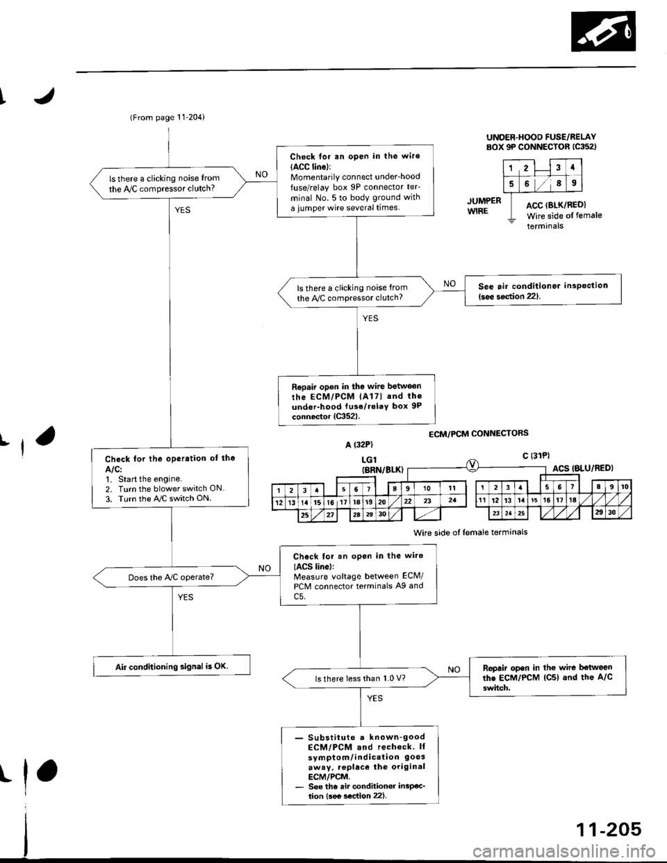
(From page 11-204)
Check for an open in the wir€(ACC linel:Momentarily connect underhood
fuse/relay box 9P connector teF
minal No. 5 to body ground with
a iumper wire several times.
ls there a clicking noise from
the IVC compressor clutch?
See air conditionor inspection(see 3oction 221.ls there a clicking noise from
the Py'C compressor clutch?
Repair open in the wire between
rhe ECM/PCM lAl7l and th6
under-hood fu3e/rolaY box 9P
connector lC352l.
Check for the oPeration of the
Alcl1. Start the engine.2. Turn the blower switch ON
3. Turn the AJC switch ON.
Chock tor an open in the wire
IACS linel:Measure voltage between ECM/
PCM connector terminals A9 and
c5.
Does the Ay'C operate?
Air conditioning signal is OK.Repair open in the wire b€tweenthe EcM/PcM lC5) and the A/c
3witch.ls there less than 1.0 V?
- Substiiute a known-goodECM/PCM and recheck ll
symptom/indication 9oesaway, .oplace the originalECM/PCM.- See the air condhioner insP€c_tion {see s€c{ion 22).
UNDER.HOOD FUSE/BELAYBOX 9P CONNECTOR 1C352)
12Ia
589
ACC (BLK/RI
Wire side ofACC (BLK/REDI
Wire side of female
terminals
JUMPERWIRE
ECM/PCM CONNECTORSrfA t32P)
LGlc {31Pl
t
(BRN/BLK)ACS IBLU/RED)
I23a9101t3I89t0
121315l611la1920232att12't3la't5t617ta
25272A2930232a2930
Wire side of lemale terminals
Page 476 of 2189

I
JUMP€RWIRE
UNDER-HOOO FUSE/RELAYsox 9P coNNEcroR lca52l
123a
5689
ACC (8LK/REDI
Wire side ofterminals
ECM/PCM CONNECTORS
A (32P1
female
Wire side of {emale terminals
(From page 11-206)
Check for an open in the wite
IACC lino):Momentarily connect under_hood
luse/relay box 9P connector teF
minal No. 5 to body ground with
a jumper wire several times.
ls there a clicking noise from
the Iy'C compressor clutch?
S6e air conditioner insPoction
l3oa section 221ls there a clicking noise lrom
the ly'C compressor clutch?
Ropair open in tho wilo betwg€n
the ECM/PCM lA17) and the A/C
clutch rolay.
Chock for the oporation of lho
AIC:1, Start the engine.
2. Turn the blower switch ON
3. Turn the ray'C switch ON.
Check lor an open in the wiro(ACS lino):Measure voltage between ECM/
PCM connector terminals A27
and 820.
Does the Iy'C operate?
Air conditioning signal is OK.Repair op6n in the wiro bctwoon
lhe ECM/PCM lA27l and tho A/C
3witch.ls voltage lessthan 1.0 V?
- Sub6iitut€ r known€ood ECtt /PCM and rccheck. ll sYmP-
tom/indication 9oe3.waY,replaca the original ECM/PCM- See the ai. condhionGr in3p€c-tion lsee soc{ion 221.
11-207
Page 479 of 2189

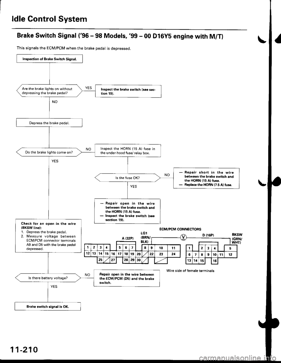
ldle Control System
Brake Switch Signal ('96 - 98 Models, '99 - 00 Dl6YS engine with M/Tl
This signals the ECM/PCM when the brake pedal is deoressed.
LGlBKSW(GRN/WHTI
D {16P)
Wire side of female t€rminals
Inspection of Brake Switch Signal.
Are the brake lights on withoutdepressing the brake pedal?
Depress the brake pedal.
Inspect the HORN (15 A) fuse inthe under-hood fuse/ relay box.Do the brake lights come on?
- Repair short in the wirebetween the brake 3whch andrhe HORN 115 At lu3e.- Replace the I|oRN 17.5 A) tus€.
Repair open in the wirebetween the brake switch andthe HORN 115 Al fuse.Inspect th6 br.ke switch {s6€section l9l.Check tor an open in the wireIBKSW line):1. Oepress the brake pedal.2. Measure voltage betweenECM/PCNI connector terminalsAg and D5 with the brake pedaloepresseo.
Repair open in the wire b€tweenthe ECM/PCM {Dsl and the brakeswitch.
ls there battery voltage?
Brakc switch sign.l is OK.
ECM/PCM CONNECTOFS
A (32PtIBRI\v
,la678101112I
121311151617t8192022232aI9101112
25212Aa3013141516
11-210