Page 1308 of 2189
Front Seat
2.
1.
3.
CUSHIONCOVER
cover all the
remove the
Seat Cover Replacement (cont'd)
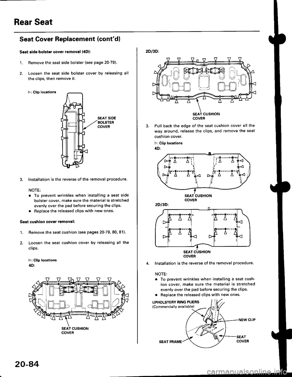
Seat cushion cover removal:
Remove the seat cushion {see pages 20,75,76).
Remove the clips from under the seat cushion, thenloosen the seat cushion cover.
>: Clip locataons
Pull back lhe edge of the seat cushion
way around, then release the clips, and
seat cushaon cover.
>: Clip locations
SEATCUSHIONCOVER
1-. v v vl
20-7A
4. Installation is the reverse of the removal procedure.
NOTE:
. To prevent wrinkles when installing a seat cush-ion cover, make sure the material is stretched
evenly over the pad before securing the clips.. Replace the released clips with new ones.
UPHOLSTERY RING PLIERS
NEW CLIP
SEAT FRAME
Page 1314 of 2189

Rear Seat
Seat Cover Replacement (cont'dl
Seat side bolstor cover removal {,lDl
1. Remove the seat side bolster (see page 20-79).
2. Loosen the seat side bolster cover by releasing all
the clios, then remove it.
>: Clip locations
SEAT SIDEBOLSTERCOVER
3. Installation is the reverse of the removal procedure.
NOTE:
. To prevent wrinkles when installing a seat side
bolster cover, make sure the material is stretched
evenly over the pad before securing the clips.
. Reolace the released cliDs with new ones,
S€at cushion covgr r6moval:
1. Remove the seat cushion (see pages 20-79, 80, 81).
2. Loosen the seat cushion cover by releasing all the
clips.
>: Clip locrtion3
4D:
- -I ./al--lt___)l ) ( .)Ll!!l^t!!l 1",
COVER
20-a4
SEAT FRAME
NEW CLIP
2DI3D:.
SEAT CUSXIONCOVER
Pull back the edge of the seat cushion cover all the
way around, release the clips, and remove the seat
cusnton cover.
>: Clip location3
/tD:
4. Installation is the reverse ofthe removal procedure.
NOTE:
. To prevent wrinkles when installing a seat cush-
ion cover. make sure the material is stretched
evenly over the pad before securing the clips.
a Replace the released clips with new ones.
UPHOLSTERY RING PLIERS
{Commerciallv available)
a\
------)
t" I FEF4+#€
R-U U m
'J)
,.ofl r_r olJr
2Dl3Dl
COVER
Page 1331 of 2189
Hatch Spoiler
Removal
NOTE: Take care not to scratch the hatch and body
1. Remove the hatch upper trim (see page 20-63)
2. Remove the nuts, and detach the clip, then lift the
hatch spoiler uP.
a: Nut locations, 4
1 2lbt.ftl _ j/
GROMMET
HIGH MOUNT BRAKELIGHT CONNECTOR
Disconnect the high mount brake light connector and
rear window washer tube, then remove the hatch
spoiler.
------,*;)
4. lf necessary. remove the spoiler trim from the spoiler
frame.
NOTE: The hatch spoiler trim for Canada produced
cars cannot be disassembled.
>: Clip locations
A>,4
>: Scr€w
5. Installation is the reverse of the removal procedure'
NOTEi
. lf necessary, replace any damaged clips.
a Make sure the connector and washer tube are
connected ProPerlY.
20-101
Page 1349 of 2189
Sub-frame
Sub-frame Torque Sequence:
CAUTION: After loos€ning the sub-frame mounting bolts, be sure to replace them with new ones.
BOLTS
10 x 1.25 mm38Nm{3.9kg{.m:
14 x 1.5 mm90 N m (9.1 ks{ m,66 rbf.ft)Replace.
28 tbf.ft)
20-119
Page 1350 of 2189
Frame Repair Chart
Unit: mm (in.)
o: Inner diameter
CVT:
DETAIL AREA.Y
(5.121
177 {6.971
20-120
Page 1368 of 2189
Reassemble in the reverse order of disassembly' and
note these items:
. Make sure the bushing and pivot washer are installed
properly.
. To connect the connecting wire, twist it 90'.
. Replace the back cover clips with new ones
. To prevent wrinkles when installing the seat-back
cover, make sure the material is stretched evenly
over the pad.
. Apply multipurpose grease to the moving portion of
the seat track.
Front Seat Torsion Bar
Replacement
NOTE| Take care not to tear the seams or damage the
seat covers.
1. Remove the seat cushlon
2. Remove the torsion bar from the hook with a flat tip
screwdriver, then pull out the torsion bar from the
seat cushion frame Put on gloves to protect your
ha nds.
TORSIONSAR
SEAT CUSHION FNAME
TORSION BARSEAT CUSHION
FLAT TIP SCREWDRIVER
3. lnstall in the reverse order of removal'
20-139
Page 1411 of 2189

Blower Unit
Replacement
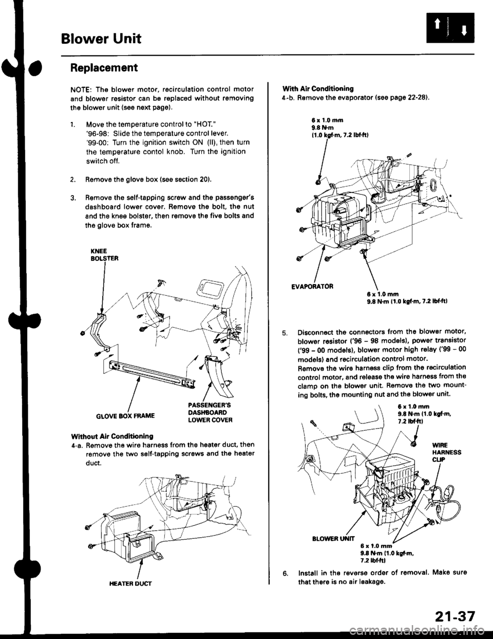
NOTE: The blower motor, recirculation control motor
and blower resistor can bs replacsd without rsmoving
th€ blower unit (see neld Page).
1. Move the temperature control to "HOT."
'96-98: Slide the temperature control lever.'99-00: Turn the ignition switch ON (ll), then turn
the temperature contol knob. Turn the ignition
switch off,
Remove the glovs box (ses ssction 20),
R€move ths s6lf-tapping screw and ths passsng6r's
dashboard low€r cover. Removo the bolt, the nut
and the kn€e bolst€r, then remove the fiv€ bolts and
the glove box trame,
Without Air Condhioning
4-a. Remove the wiro harness from the h68t€r duct, then
remove the two self-tapping scrsws and the heatsr
duct.
KNEE
GLOVE BOX FRAME
HEATER DUCT
21-37
Wrth Air Conditioning
4-b. Removo th6 ev8porator (sss pago 22-28).
6x1.0m|n9.8 N'm
6x1.0mm9.8 N'm lt'o tgf'm, t.2 lb{'ttl
Disconnoct the connectors trom th€ blower motor,
blowor r6sistor {'96 - 98 models), power transiator
('99 - 0O modsls), blowor motor high telay ('99 - 00
models) and recirculation control motor.
R€mov€ ths wiro harnoss clip from tho recirculation
control motor, and release the wir6 harnsss from ths
clamo on the blowor unit. Remove the two mount-
ing bolts, tho mounting nut and ths blowor unit'
9.8 .m 11.0 tgfm,1.2 tblfrl
lnstall in ths reverso order of removal. Mako surs
that thsre is no air leaka96.
6x1.0mm9,t N'm 11.0lgi.m,7.2 tbf.fil
Page 1452 of 2189

Evaporator
1.
Replacement
4.
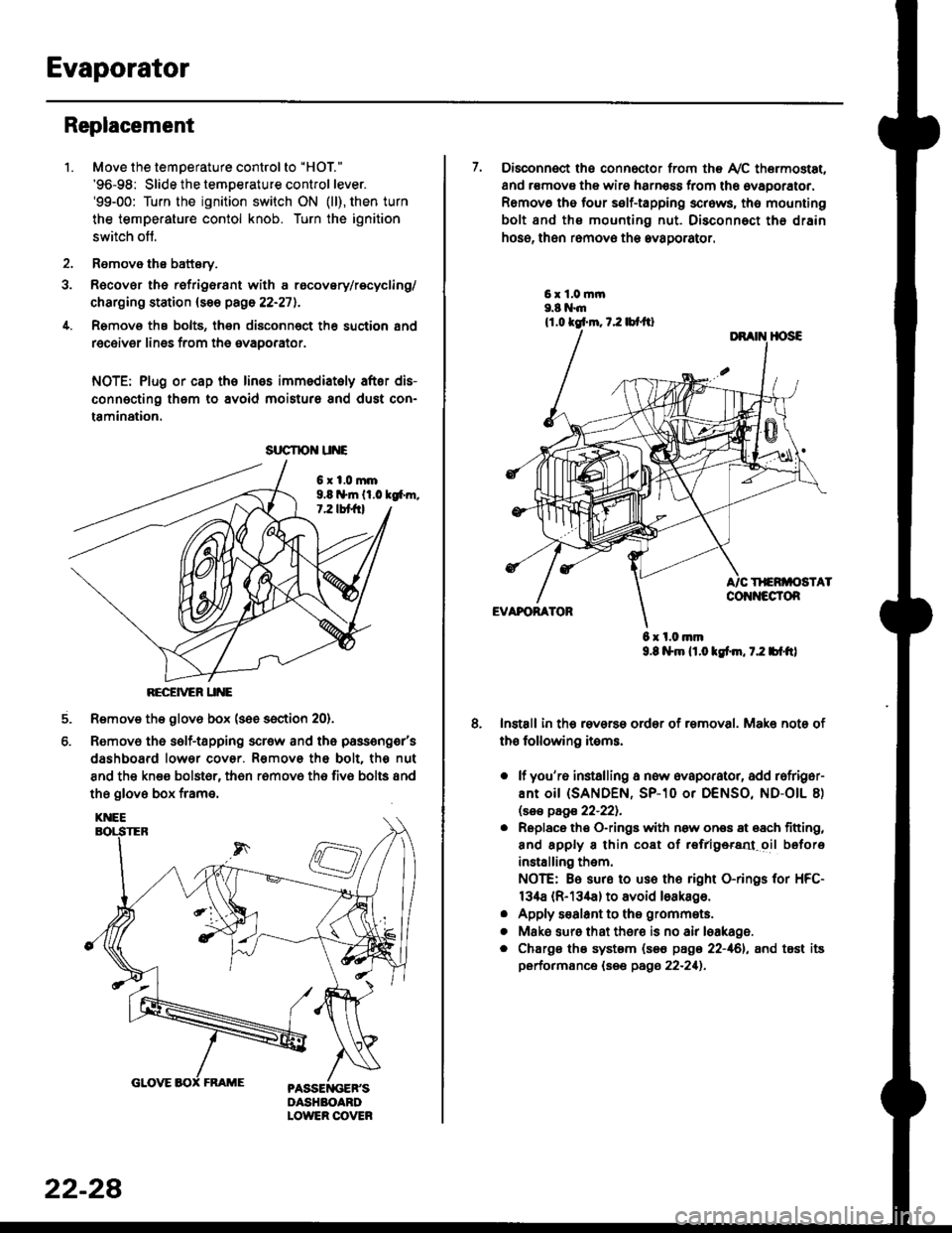
Move the temperature control to "HOl"
'96-98: Slide the temoerature control lever.'99-00: Turn the ignition switch ON (ll), then turn
the temperature contol knob. Turn the ignition
switch off.
Remove the battsry.
Rgcover the refrigerant with a rocovery/recycling/
charging station (see page 22-271.
Remove the bolts, then disconnect th6 suction 8nd
receiver lines from th6 evaoorator.
NOTE: Plug or cap the lines imm€diatoly after dis-
connecting them to avoid moisture and dust con-
tamination.
6xl.0mm9.8 n*ln ll.0 tg6m.7.2 lbt frl
RECEiVER UNE
Remove the glov6 box (see section 20).
Removo the self-tapping scr€w and the passeng€r's
dashboard lower cover. Removs the bolt. the nut
8nd the kn€e bolst6r, th6n r6mov6 th6 fiv6 bolts and
the glove box frame.
6.
srrcrrc u E
22-28
7. Disconnect the connector from th€ Ay'C thermostat,
and r€movs the wire harness from the ovaporator.
Remov6 tho four self-tapping screws, tho mounting
bolt and ths mounting nut. Disconnect th€ drain
hose, then remov€ th6 avagorator.
6 x l.0.nm9.8 l$m lt.o ldm, 7.2 bl.tt)
Install in the reverse order of removal. Make note of
th€ following items.
o lf you'r6 installing a new evaporator, add rofriger-
ANt OiI {SANDEN, SP-10 Or DENSO, ND-OIL 8)
lsas page 22-221.
. Replace the O-rings with now ones 8t 68ch titting,
and apply 8 thin coat of r€frlgersd oil before
installing them.
NOTE: Be sure to use the right O-rings for HFC-
134a (R-134a) to avoid loakago.
. Apply s€alant to tha grommets.
. Mske sure that ther€ is no air leakage.
. Chargs ths system {s€€ page 22-161, and tost its
performance (see pags 22-211.