Page 1143 of 2189
\Reassembly
2.
't.
lr
Install the damper unit on a spring compressor.
Assemble the damper in reverse order of removal
except the damper mounting washer and self lock-
ing nut.
NOTE: Align the bottom of the damper spring and
spring lower seat as shown.
STRUTSPRING COMPRESSOR:
lcommercially availablelBRANICK@ T/N MST.58OA, T/N 7200,
or 6quival€nt
SPBING LOWER SEAT
Position the damper mounting base onto the
damper unit as shown.
Compress the damPer sPring.
Install the damper mounting rubber, damper mount-
ing washer, and a new 10 mm self-locking nut.
Hold the damper shaft. and tighten the 10 mm self-
locking nut.
SELF-LOCKING NUT10 x 1.25 mm29 N.m 13.0 kgf m, 22 lbf ft)
3.
4.
Replace.
DAMPERMOUNTING WASHER
(l-t
lnstallation
1. Loosely install the damper onto the frame with the
aligning tab facing inside. then loosely install the
two flange nuts.
FLANGE NUTS10 x 1 ,25 mm49 N.m (5.0 kgt'm, 36 lbf'ftl
DAMPER ASSEMBLY
{cont'd)
18-19
Page 1231 of 2189
l}
e\
Body ('96 modell
Doors
Front Door Index (4D) ...20-2
Rear Door Index {4Dl .....20-8
Door fndex lzDl3Dl .......20-14
Emblems
f nstallation 20-118
Exterior
Component Location Index ............... 20-93
*Frame Repair Chart .......... 20-120
* Interior
Component Location Index ............... 20-58
Mirrors
Mirror Rep|acement .................. ......... 20-24
Mirror Holder/Gover Replacement ... 20-25
Rearview Mirror Reolacement .......... 20-25
Moonroof
lndex .......... .....................20-50
Opener Cable/Opener and Latch/
Wiper and Washer
Component Location Index .......... ...,. 20-107
Seats and Seat Belts
Gomponent Location Index .......... ..... 20-73
Sub-frame ....20-119
Windshield, Rear Window and Ouarter Glass
Index .......... .....................20-26
Body {'97 modell
Body ('98 modell
Body ('99 modell
Body ('00 model)
20-123
20-131
20-135
20-141
It
Page 1281 of 2189

Troubleshooting
SymptomProbable Cause
Water leaks1. Clogged drain tube.
2. Gap between glass weatherstrjp and roof panel.
3. Defective or improperly installed glass weatherstrip.
4. Gap between drain seal and roof panel.
Wind noise'1. Excessive clearance between glass weatherstrip and roof panel.
Motor noise1. Loose motor.
2. Worn gear or bearing.
3. Cable assembly deformed.
Glass does not move, but motor turns'1. Clutch out of adjustment.
2. Foreign matter stuck between guide rail and slider.
3. lnner cable loose.
4. Cable assembly not attached properly.
Glass does not move and motor does not turn
{glass can be moved with moonroof wrench)
1. Blown fuse,
2. Faulty switch.
3. Battery run down.
4. Defective motor.
5. Faulty relay.
D
Glass Height Adjustment
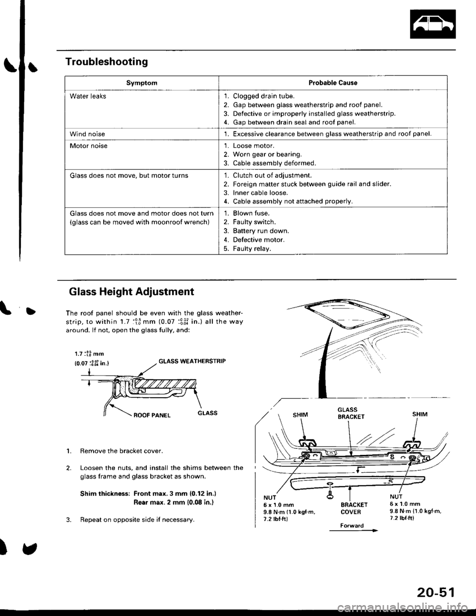
The roof panel should be even with the glass weather-
strip, to within 1.7 :lr3 mm (0.07 :3:31 in.) all the way
around. lf not, open the giass fully, and:
GLASS WEATHERSTRIP
1. Remove the bracket cover.
Loosen the nuts, and install the shims between the
glass frame and glass bracket as shown.
Shim thickness: Front max.3 mm 10,12 in.l
Rear max. 2 mm 10.08 in.)
Repeat on opposite side i{ necessary.
)
5x1.0mm9.8 N.m 11.0 kgf m,7.2 rbtft)
SRACKETCOVEB
----------1>
6x1.0mm9.8 N.m {1.0 kgtm,7.2 tbf.ft)
1.7 tl.8 mm
{0.07 :3 3i in.}
20-51
Page 1284 of 2189
Moonroof
Motor, Drain Tube and Frame Replacement
CAUTION:
. Put on gloves to protecl your hands.
. Be careful not to damage the seats, dashboard and other interior trim.
'1. Remove the headliner {see page 20-64).
2. Disconnect the motor connector and glass position switch connector.
NOTE: When removing the motor, detach the connector from the frame, remove the bolts and nuts, then remove the
motor.
3. Remove the glass {see page 20-52).
4. Disconnect the drain tubes, and detach the ceiling light harness.
5. Remove the frame mounting bolts.
NOTE;
. An assistant is helpful when removing the bolts.
. Remove the front bolts last.
6. Detach the rear hooks by moving the frame forward, then remove the frame.
BOLT6x1.0mm9.8 N.m {1.0 kgt m,7.2 tht.hl
6x1.0mm9.8 N m (1.0 kgl.m, 7.2 lbtft)
20-54
\
Page 1285 of 2189

L
L
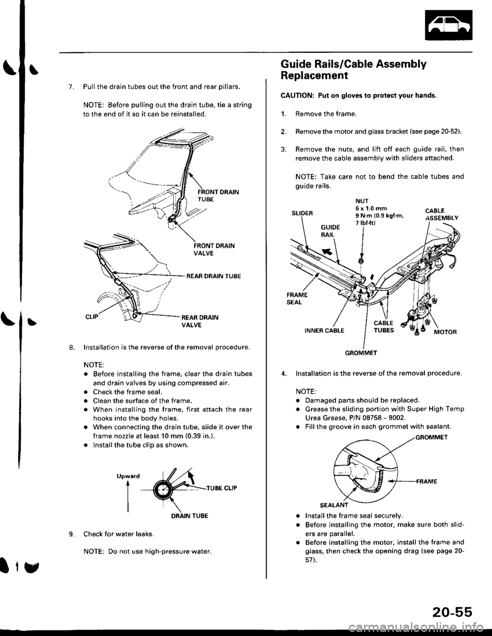
7. Pull the drain tubes out the front and rear pillars.
NOTE: Before pulling out the drain tube, tie a string
to the end of it so it can be reinstalled.
Installation is the reverse of the removal procedure.
NOTE:
. Before installjng the frame, clear the drain tubes
and drain valves by using compressed air.
. Check the frame seal.
. Clean the surface of the frame.
. When installing the frame, first attach the rear
hooks into the body holes.
. When connecting the drain tube, slide it over the
frame nozzle at least 10 mm (0.39 in.).
. Install the tube clip as shown.
UpwardI
I
I
TUBE CLIP
Check for water leaks.
NOTE: Do not use high-pressure water.
DRAIN TUBE
Ity
20-55
Guide Rails/Cable Assembly
Replacement
CAUTION: Put on gloves to protect your hands,
1. Remove the frame.
Remove the motor and glass bracket (see page 20-52).
Remove the nuts, and lift off each guide rail, then
remove the cable assembly with sliders attached.
NOTE: Take care not to bend the cable tubes and
guide rails.
Installation is the reverse of the removal procedure.
NOTE:
. Oamaged parts should be replaced.
. Grease the sliding portion with Super High Temp
Urea Grease, P/N 08758 - 9002.
. Fillthe groove in each grommet with sealant.
a
a
Install the frame seal securely.
Before installing the motor. make sure both slid-
ers are parallel.
Before installing the motor. install the frame and
glass, then check the opening drag (see page 20-
GROMMET
Page 1300 of 2189

Dashboard
Gomponent Removal/lnstallation
(cont'd)
Center panel removal:
1. Remove:
. Center dashboard lower cover (see page 20-69)
. Radio {see section 23)
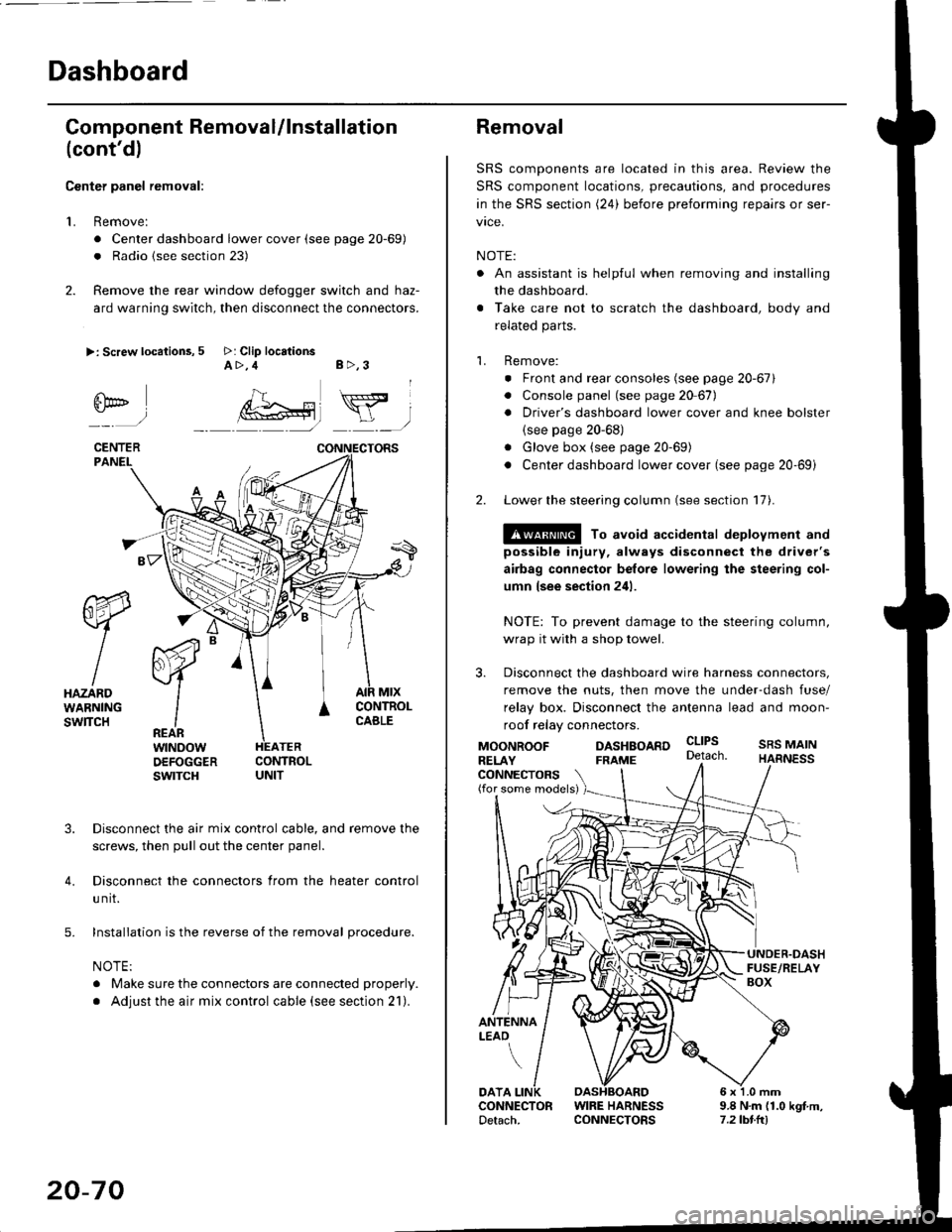
2. Remove the rear window defogger switch and haz-
ard warning switch, then disconnect the connectors.
>: Screw locations, 5 >: Clip locationsA>,4 B>,3
fii*-)
CENTERPANEI.
rt-xR.
W
IHAZARDWARNINGswlTcH
r44 "
F.IZvl
IIREARwtNoowOEFOGGERswtrcH
MtxCONTNOLCABLE
3. Disconnect the air mix control cable, and remove the
screws, then pull out the center panel.
4. Disconnect the connectors from the heater control
u nit.
5. Installation is the reverse of the removal procedure.
NOTE:
. Make sure the connectors are connected properly.
. Adjust the air mix control cable (see section 21).
20-70
Removal
SRS components are located in this area. Review the
SRS component locations, precautions, and procedures
in the SRS section (24) before preforming repairs or ser-
vice.
NOTE:
. An assistant is helpful when removing and installing
the dashboard.
. Take care not to scratch the dashboard, body and
related parts.
1. Remove:
o Front and rear consoles (see page 20-67)
. Console panel (see page 2O 67),
. Driver's dashboard lower cover and knee bolster(see page 20-68)
. Glove box (see page 20-69)
. Center dashboard lower cover (see page 20-69i
2. Lower the steering column (see section 17).
@ To avoid accidental deplovment and
possible injury, always disconnect the driver's
airbag connector belore lowering the steering col-
umn lsee section 241.
NOTE: To prevent damage to the steering column,
wrap it with a shop towel.
3. Disconnect the dashboard wire harness connectors,
remove the nuts, then move the under-dash fuse/
relay box. Disconnect the antenna lead and moon-
roof relay connectors.
DASHBOARD cltPs
CONNECTORS(for some models)
MOONROOFRELAY
ANTENNALEAO
FRAME
SRS MAINHARNESS
9.8 N.m (1.0 kgf m,7.2lbt.ltl
DATACONNECTOR WIRE HARNESSDetach. CONNECTORS
Page 1302 of 2189
Dashboard
Removal (cont'd)
7. lf necessary, remove the dashboard frame from the dashboard.
>: Screw localionsa>,21 B>,4a: Nut locations, 3
>: Clip locations
l^1./'\
I Shl:' Olb'tvY/l\-]1
ra 6 x '1.0 mm
Yi.!i[11"-"'".
DASHBOARD BRACKETSIDE COVER
Installation is the reverse of the removal orocedure.
NOTE:
. Before tightening the bolts, make sure the dashboard wire harnesses are not pinched.a Make sure the connectors, antenna lead and air mix control cable are connected properly.
FRONT PASSENGER'S
OASHBOARD
20-72
Page 1307 of 2189
Harness Wiring and Recline
Cable Locations
NOTE: When installing the seat cushion, make sure the
seat belt switch harness, connector and recline cable are
fastened correctly on the seat cushion frame'
Driver's:>: Clip locations
Passenger's (with lecline cablel:
TRACK
Seat Cover RePlacement
CAUTION: Put on gloves to protest yout hands'
NOTE: Take care not to tear the seams or damage the
seat covers.
Seat-back cover removal:
1. Release the hook, and fold back the seat-back cover'
Release all inside springs, then fold back the seat-
back cover.
Remove the headrest.
Remove the headrest guide, then remove the seat-
back cover.
lnst;llation is the reverse of the removal procedure'
NOTE: To prevent wrinkles when installing a seat-
back cover, make sure the material is stretched evenly
over the pad before securing the inside springs and
hook.
3.
(cont'd)
20-77
HEADREST