1999 HONDA CIVIC Integrated control
[x] Cancel search: Integrated controlPage 2036 of 2189
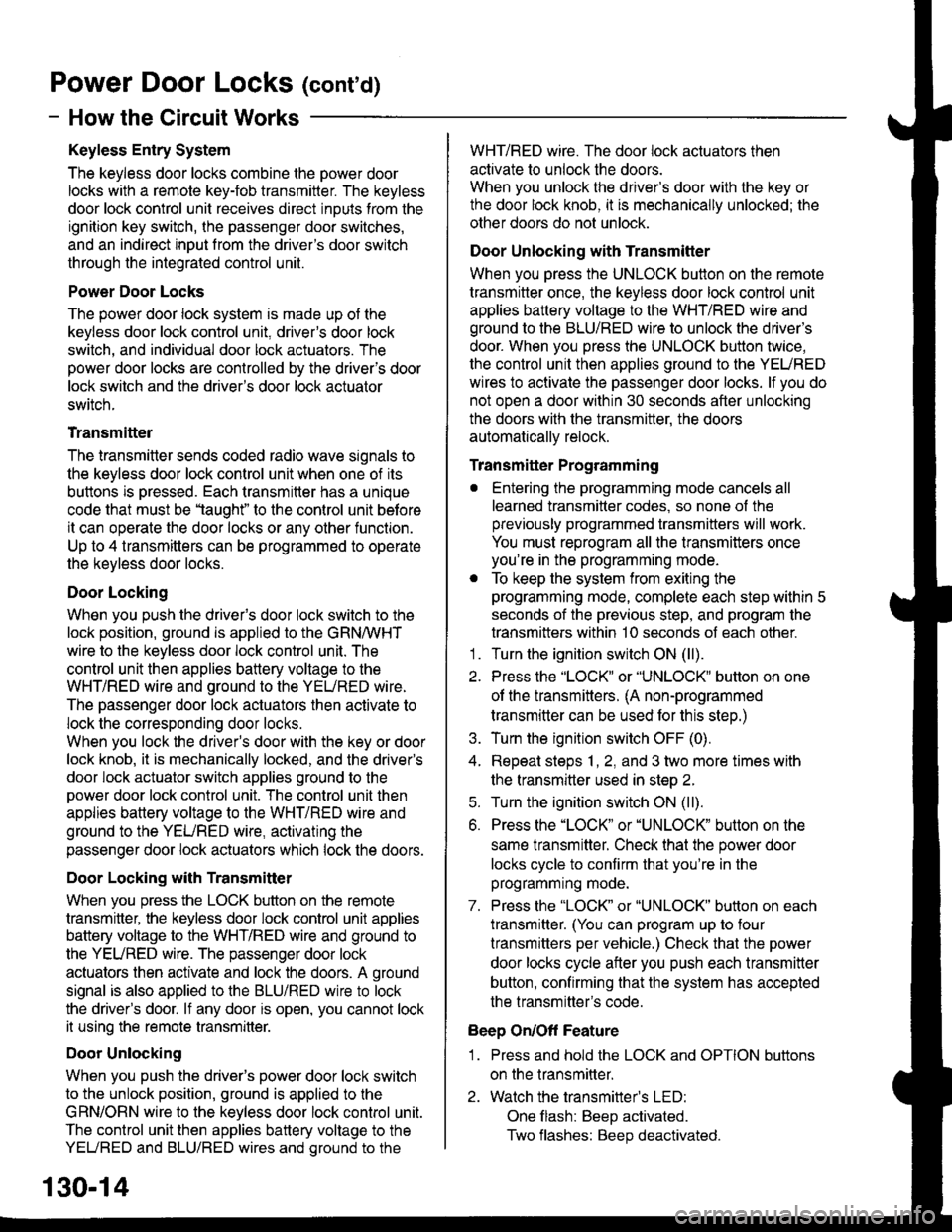
Power Door Locks (conrd)
- How the Circuit Works
Keyless Entry System
The keyless door locks combine the power door
locks with a remote key-fob transmitter. The keyless
door lock control unit receives direct inputs from the
ignition key switch, the passenger door switches,
and an indirect inDut from the driver's door switch
through the integrated control unit.
Power Door Locks
The power door lock system rs made up ot the
keyless door lock control unit, driver's door lock
switch, and individual door lock actuators. The
power door locks are controlled by the driver's door
lock switch and the driver's door lock actuator
switch.
Transmittel
The transmitter sends coded radio wave signals to
the keyless door lock conlrol unit when one of its
buttons is pressed. Each transmitter has a unique
code that must be 'laught" to the conlrol unit before
it can operate the door locks or any other function.
Up to 4 transmitters can be programmed to operate
the keyless door locks.
Door Locking
When you push the driveas door lock switch to the
lock position, ground is applied to the GRNMHT
wire to the keyless door lock control unit. The
control unit then applies battery voltage to the
WHT/RED wire and ground to the YEURED wire.
The passenger door lock actuators then activate to
lock the corresponding door locks.
When you lock the dnver's door with the key or door
lock knob, it is mechanically locked, and the driver's
door lock actuator switch applies ground to the
oower door lock control unit. The control unit then
applies battery voltage to the WHT/RED wire and
ground to the YEURED wire, activating the
passenger door lock actuators which lock the doors.
Door Locking with Transmitter
When you press the LOCK button on the remote
transmitter, the keyless door lock control unil applies
battery voltage to the WHT/RED wire and ground to
the YEURED wire. The passenger door lock
actuators then activate and lock the doors. A ground
signal is also applied to the BLU/RED wire to lock
the driver's door. lf any door is open, you cannot lock
it using the remote transmitter.
Door Unlocking
When you push the driver's power door lock switch
to the unlock position, ground is applied to the
GRN/ORN wire to the keyless door lock control unil.
The control unit then applies battery voltage to the
YEUREO and BLU/RED wires and oround to the
WHT/RED wire. The door lock actuators then
activate to unlock the doors.
When you unlock the driver's door with the key or
the door lock knob, it is mechanically unlocked; the
other doors do not unlock.
Door Unlocking with Transmitter
When you press the UNLOCK button on the remote
transmitter once, the keyless door lock control unit
applies battery voltage to the WHT/RED wire and
ground to the BLU/RED wire to unlock the driver's
door. When you press the UNLOCK button twice,
the control unit then applies ground to the YEURED
wires lo activate the passenger door locks. lf you do
not open a door within 30 seconds after unlocking
the doors with the transmitter, the doors
automatically relock.
Transmitter Programming
. Entering the programming mode cancels all
learned transmitter codes, so none of the
previously programmed transmitters will work.
You must reprogram all the transmitters once
you're in the programming mode.
. To keep the system from exiting the
programming mode, complete each step within 5
seconds of the previous step, and program the
transmitters within 10 seconds of each other.'1 . Turn the ignition switch ON (ll).
2. Press the "LOCK" or "UNLOCK" button on one
of the transmitters. (A non-programmed
transmitter can be used for this step.)
3. Turn the ignition switch OFF (0).
4. Repeat steps 1, 2, and 3 two more times with
the transmitter used in step 2.
5. Turn the ignition switch ON (ll).
6. Press the "LOCK" or "UNLOCK" button on the
same transmitter. Check that the power door
locks cycle to confirm that you're in the
programmrng mooe.
7. Press the "LOCK" or "UNLOCK" button on each
lransmitter. (You can program up to four
lransmitters per vehicle.) Check that the power
door locks cycle after you push each transmitter
button, contirming that the system has accepted
the transmitter's code.
Beep On/Off Feature
1 . Press and hold the LOCK and OPTION buttons
on the transmitter.
2. Watch the transmitter's LED:
One flash: BeeD activated.
Two flashes: Beep deactivated.
130-14
Page 2108 of 2189
-
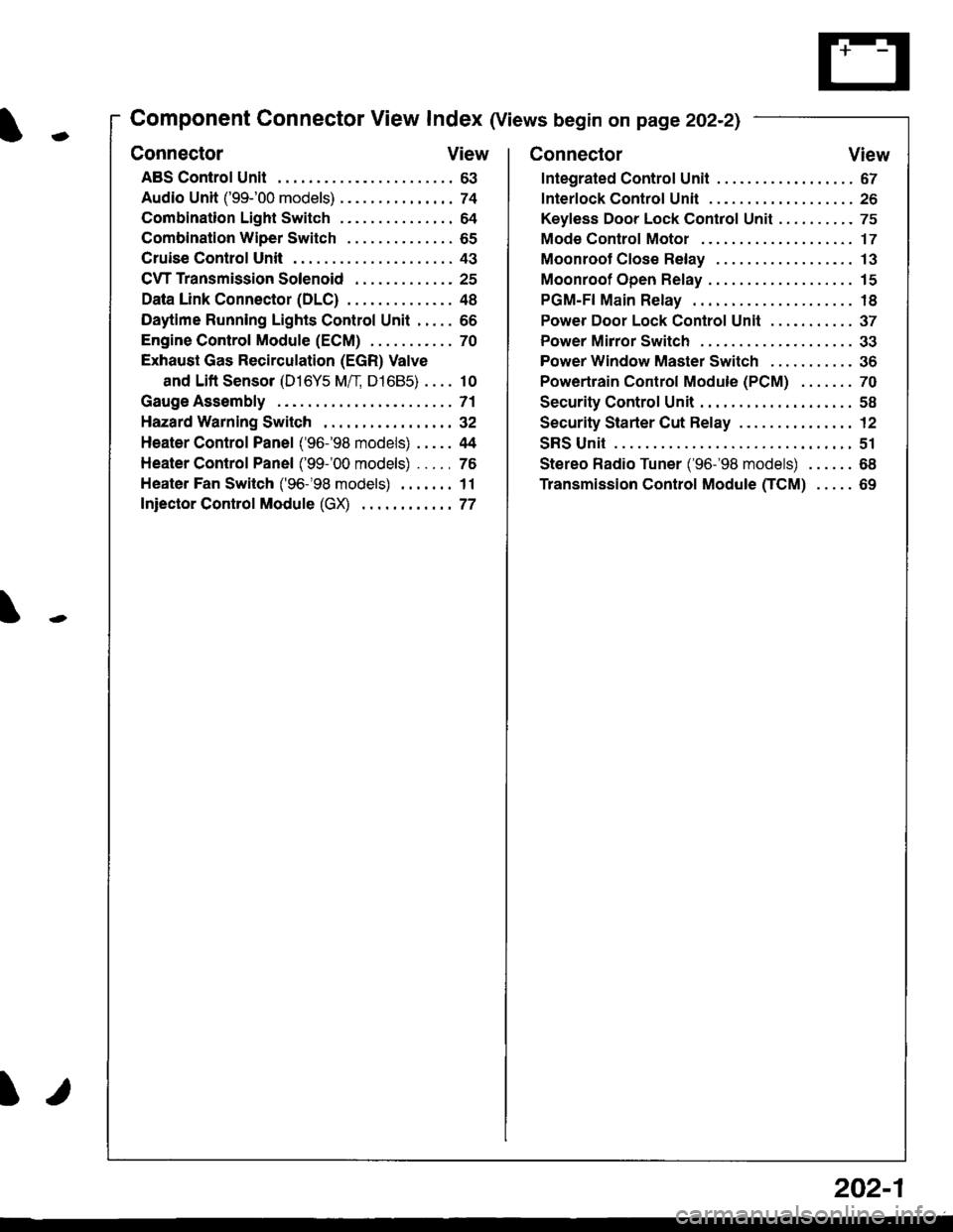
Component Connector View Index (Views begin on page 202-21
Connector View
ABS Control Unit........ ......63
Audio Unit ('99-'00 models) ......74
Combination Light Switch . . . . . . . . . . . . . . . 64
Combination Wiper Switch . . . . . . . . . . . . . . 65
Cruise Control Unit.... .....43
C\TTTransmission Solenoid ............. 25
Data Link Connector (DLC) ..... 48
Daytime Runnlng Lights Control Unit ..... 66
Engine control Module (ECM) ...........70
Exhaust Gas Recirculation (EGR) Valve
and Lift Sensor (D16Y5 Mfl, D1685) . . . . 10
Gauge Assembly .............71
HazardWarnlngSwitch,,. .,,,...,,,,... 32
Heater Control Panel ('96-'98 models) .....44
Heater Control Panel ('99-'00 models) ...., 76
Heater Fan Switch ('96-'98 models) ,,,.... 11
fniector Control Module (GX) ............77
I/
202-1
Connector View
Integrated Control Unit .......,. 67
f nterfock Control Unit .... ...... 26
Keyfess Door Lock Control Unit . . . . , . . . . . 75
Mode Control Motor ... ........'17
Moonroof Close Relay .. .......13
Moonroof Open Relay ... .......15
PGM-FI Main Relay .. .......... 18
Power Door Lock Conlrol Unil ..... ...... 37
Power Mirror Switch .,... ...... 33
Power Window Master Switch .,.........36
Powertrain Control Module (PCM) .......70
Security Control Unit ..., ..,,... 58
Security Starter Cut Belay ... ...,,,....,, 12
SRS Unit ............. 51
Stereo Radio Tuner ('96-'98 models) ...... 68
Transmission Control Module CICM) .....69
Page 2131 of 2189
Gonnector Views (cont'd)
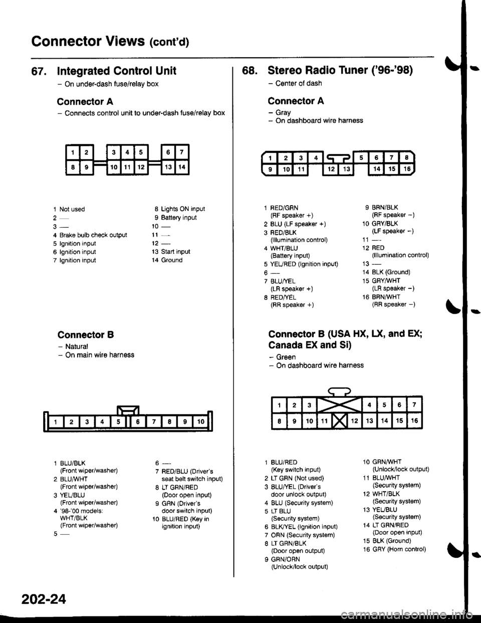
67. Integrated Control Unit
- On underdash fuse/relay box
Connector A
- Connects control unit to under-dash fuse/relay box
1 Not used
4 Erake bulb check output
5 lgnition input
6 lgnition input
7 lgnjtion input
Connectol B
- Natural- On main wire harness
l BLU/BLK
{Front wiper/washer)
2 BLUA/VHT(Front wiper/washe0
3 YEUBLU(Front wiper/washer)
4 '98-'00 models:WHT/BLK(Front wiper/washer)
8 Lights ON input
9 Battery input
11 _
13 Start input
14 Ground
7 RED/BLU (Driver's
seat b€lt switch input)
8 LT GRN/RED(Door open input)
I GRN (Oriver's
door switch input)'t0 BLU/RED (Key inignition input)
202-24
68. Stereo Radio Tuner ('96-'98)
- Center ot dash
Connector A
- Gray- On dashboard wire harness
1 RED/GRN(RF speaker +)
2 BLU (LF speaker +)
3 RED/BLK(lllumination control)
4 WHT/BLU(Battery input)
5 YEURED (lgnition input)
6-
7 BLU/YEL(LR speaker +)
8 RED/TEL(RR speaker +)
9 BRN/BLK(RF speaker -)
1O GRY/BLK(LF speaker -)
12 RED(lllumination control)
14 BLK (Ground)
15 GFY,4/VHT(LR speaker -)
16 BRNAVHT(RR speaker -)
Connector B (USA HX, UX, and EX;
Canada EX and Si)
- Green- On dashboard wire harness
l BLU/RED(Key switch input)
2 LT GRN (Not used)
3 BLU/'EL (Drivels
door unlock output)
4 BLU (Security system)
5 LT BLU
{Security system)
6 BLIVYEL (lgnition input)
7 ORN (Security system)
8 LT GRN/BLK(Door open output)
9 GRN/ORN(Unlock/lock output)
1O GRNAVHT(Unlock/lock output)
1 1 BLU/WHT(Security system)
'2 WHT/BLK(Security system)
13 YEUBLU(Security system)
14 LT GRN/RED(Door open input)
15 BLK (Ground)
16 GRY (Horn conkol)
Page 2161 of 2189
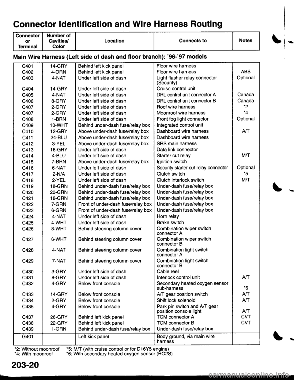
Connector ldentification and Wire Harness Routing
Connector
or
Terminal
Number ol
Cavities/
Color
LocationConnects toNotes
Main Wire Harness (Left side of dash and floor branch): '96-'97 models
c401
c402
c403
c404
c405
c406
c407
c407
c408
c409
c410
c411
c412
c413
c414
c415
c416
c417
c418
c419
c420
c421
c422
w+4J
c424
c425
c427
c428
c429
c430
c431
c432
c433
c434
lJ+OC
c437
v+.to
c439
14-GRY
4-ORN
4-NAT
14-GRY
4-NAT
8-GRY
2-GRY
2-GRY
1-BRN
1O-WHT
12-GRY
24-BLU
3-YEL
16-GRY
4.BLU
7-BRN
6.NAT
2-N/A
2-YEL
18-GRN
2O.GRN
18-GRN
7-GRN
6-GRN
4-NAT
4-WHT
8.WHT
6-WHT
4-NAT
7-NAT
3-GRY
8-GRY
4.GRY
14-GRY
2-GRY
4-GRY
26-GRY
22-GRY
1-GRN
Behind left kick panel
Behind left kick panel
Under left side ot dash
Under left side of dash
Under left side of dash
Under left side of dash
Under lett side ot dash
Under left side of dash
Under left side of dash
Behind under-dash fuse/relay box
Above under-dash fuse/relay box
Above under-dash fuse/relay box
Above under-dash fuse/relay box
Under left side of dash
Under left side of dash
Above under-dash fuse/relay box
Under left side of dash
Under left side of dash
Under left side of dash
Behind under-dash fuse/relay box
Behind under-dash fuse/relay box
Behind under-dash fuse/relay box
Front of under-dash iuse/relay box
Front of under-dash fuse/relay box
Under left side of dash
Under left side of dash
Behind steering column cover
Behind steering column cover
Behind steering column cover
Behind steering column cover
Under left side of dash
Under lett side ot dash
Below front console
Below front console
Below front console
Below front console
Behind lett kick panel
Behind left kick panel
Behind under-dash fuse/relay box
Floor wire harness
Floor wire harness
Light flasher relay connector(Security)
Cruise control unit
DRL control unit connector A
DRL control unit connector B
Roof wire harness
Moonroof wire harness
Front fog light connector
Integrated control unit
Dashboard wire harness
Dashboard wire harness
SRS main harness
Data link connector
Starter cut relay
lgnition switch
Security starter cut relay conneclor
Clutch switch
Clutch interlock switch
Under-dash fuse/relay box
Underdash fuse/relay box
Under-dash fuse/relay box
Under-dash fuse/relay box
Underdash fuse/relay box
Horn relay
Brake switch
Combination wiper switch
connector A
Combination wiper switch
connector B
Combination light swilch
connector A
Combination light switch
connector B
Cable reel
lnterlock control unit
Secondary heated oxygen sensor
sub-narness
A,/T gear position switch
Shift lock solenoid
Park pin switch and A,/T gear
position console light
TCM connector A
TCM connector B
Under-dash luse/relay box
ABS
Optional
Canada
Canada-2
'4
Optional
AtT
M/T
Optional'5
M/T
Atl
'6
AN
AN
Atf
CVT
CVT
G401Left kick panelBody ground, via main wire
harness
.2: Without moonroof .5: M/T (with cruise control or for D16Y5 engine)"4: With moonroof .6: With secondary heated oxygen sensor (HO2S)
203-20
Page 2163 of 2189
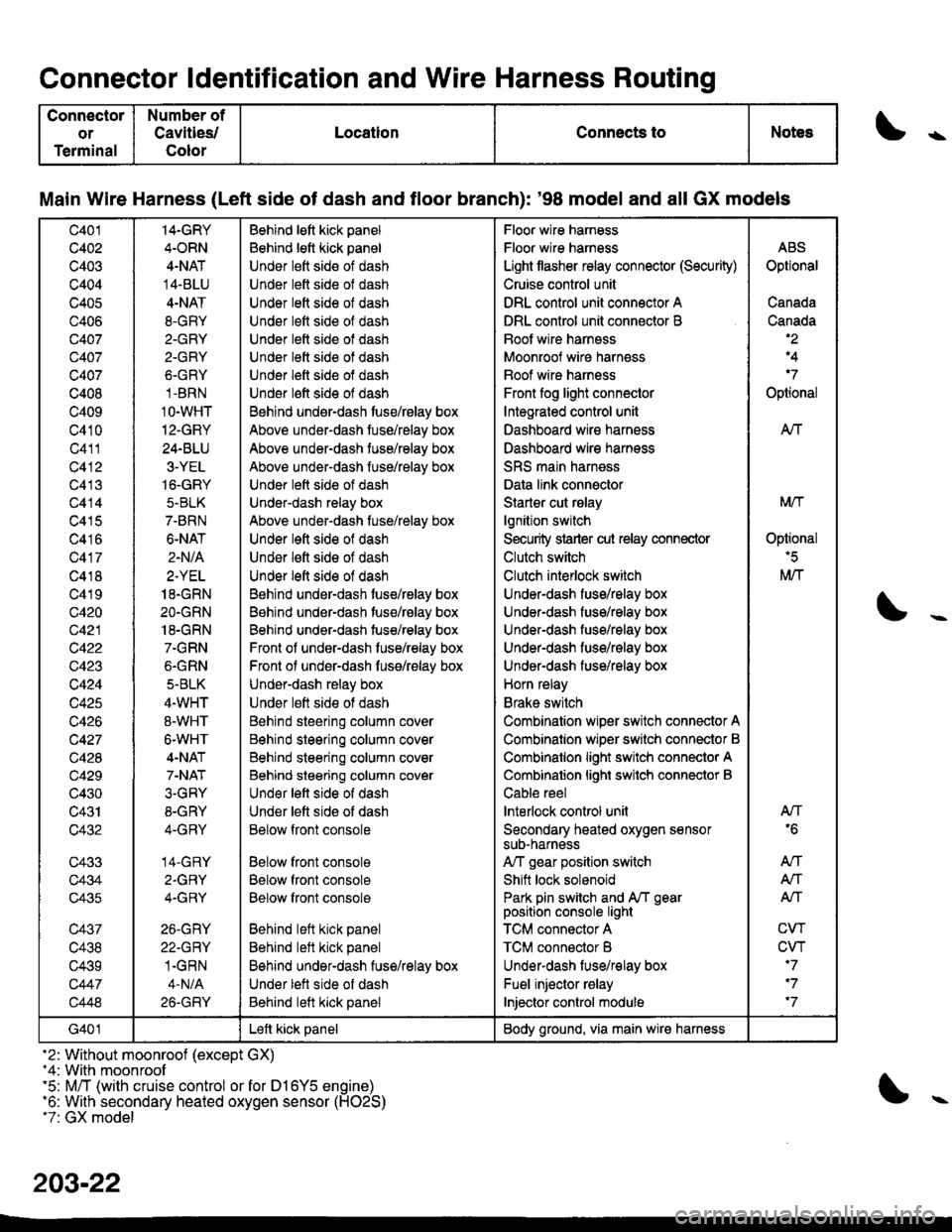
Connector ldentification and Wire Harness Routing
Connector
or
Terminal
Number of
Cavities/
Color
LocationConnects toNotess
Main Wire Harness (Left side of dash and tloor branch): '98 model and all GX models
c401
c402
c403
c404
c405
c406
Q407
c407
c407
c408
c409
c410
c411
c412
c413
c414
c415
c416
c417
c418
c419
c420
c421
c422
c423
c424
c425
c426
c427
c428
c429
c430
c431
c432
c433
c434
c435
c437
c438
c439
c447
c448
14-GRY
4.ORN
4-NAT
14-BLU
4-NAT
8.GRY
2.GRY
2-GRY
6.GRY
1-BRN
1O-WHT
12-GRY
24-BLU
3-YEL
16-GRY
5-BLK
7-BRN
6-NAT
2.N/A
2.YEL
18.GRN
2O.GRN
18-GRN
7.GRN
6.GRN
5-BLK
4.WHT
8-WHT
6-WHT
4-NAT
7-NAT
3.GRY
8-GRY
4-GRY
14-GRY
2.GRY
4.GRY
26.GRY
22-GRY
1.GRN
4-N/A
26-GRY
Behind lett kick panel
Behind lett kick panel
Under lett side of dash
Under lett side ol dash
Under lett side of dash
Under left side of dash
Under lett side of dash
Under lett side ot dash
Under left side of dash
Under l€ft side of dash
Behind undsr-dash tuse/rBlay box
Above under-dash tuse/relay box
Above under-dash tuse/relay box
Above under-dash fuse/relay box
Under lett side of dash
Under-dash relay box
Above under-dash tuse/relay box
Under left side of dash
Under lett side of dash
Under left side of dash
Behind under-dash tuse/relay box
Behind under-dash tuse/relay box
Behind under-dash tuse/relay box
Front of under-dash tuse/relay box
Front ol under-dash fuss/relay box
Under-dash relay box
Under lett side ot dash
Behind steering column cover
Behind steering column cover
Behind steering column cover
Behind steering column cover
Und€r left side of dash
Under lett side of dash
Below front console
Below front console
Below front console
Below front console
Behind left kick panel
Behind left kick panel
Behind under-dash fuse/relay box
Under lett side of dash
Behind left kick panel
Floor wire harness
Floor wire harness
Light tlasher relay connector (Security)
Cruise control unit
DRL control unit connector A
DRL control unit connector B
Boot wire harnsss
Moonroof wire harness
Boof wire harness
Front fog light connector
Integrated control unit
Dashboard wire harness
Dashboard wire harness
SRS main harness
Data link connector
Starler cut rslay
lgnition switch
Security strarter cut relay connector
Clutch switch
Clutch interlock switch
Under-dash fuse/relay box
Under-dash fuse/relay box
Under-dash fuso/rolay box
UndeFdash fuse/relay box
Under-dash fuse/relay box
Horn relay
Brake switch
Combination wiper switch connector A
Combinalion wiper srvitch connector B
Combinalion light switch connector A
Combinalion lighi swilch connector B
Cable reel
lnterlock control unil
Secondary heated oxygen sensorsuD-narness
A,/T gear position switch
Shift lock solenoid
Park pin switch and A/T gearposition console light
TCM connector A
TCM connector B
Underdash lus€/relay box
Fuel injector relay
Injector control module
ABS
Optional
Canada
Canada,2
,4
'7
Optional
AIf
Mtf
Oplional'5
M/T
AN'6
An
A,/T
Alf
CW
CVT'7
'7
'7
G401Left kick panelBody ground, via main wire harness
-2: Without moonroof (except GX)-4: With moonroof'5: M/T (with cruise control or for D16Y5 engine)'6: With secondary heated oxygen sensor (H02S)t7: GX model
203-22