Page 1862 of 2189
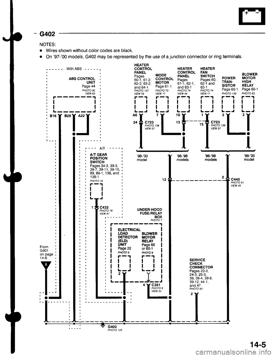
- G402
NOTES:
. Wires shown without color codes are black.
. On '97-'00 models, G402 may be represented by the use of a junction connector or ring terminals.
with ABS - - - - - I
. ABS CONTROL I' ultt '
HEATERCONTROL HEATER HEATER
iili, BB-'fi",. Eiff* 5fi::g PowER i,8;g'"'
;;; ;;; MoroR ;il--"'. ;;1-;; rRAN- H|GH
!if,6f1- ease ot-t Ino b5-.t ' fi i *- slsroR FELAY- ,pHaTa t3z pHoro 70 photoT. iioro ^ Page 60-1 Page 60-1vtEw 76 vlEW 17 V|EW 44 V|EW11 PHOTO139 PHOTO 83
r-1r-.!r-1r-1r-.|r-1
| | | | | | rl I lll
| | | | | | I ll ll IL-J L-J L-J L.J L-J L-J
Page 44PHOTO 85vtEW 63
I
I------J
I""IJ
Ifnn*"1 r'[
1"""LI'--- A/l ---_r
i , m cean; I POStflON, : swrrcH :' , Pages 34-3, 39-3, :' | 39-7,39-11,39-15,;: ' 89, 89-1, 138, and ,
; : 138-1| | PHO|OIA :' , F-'t .
'99-'00
mooel
'96-'�98
moo€ts
'9G'S
mod6ls
'99-'00
modol
a
12c440
vtEw 45
FromG401on page14-6.
v
l-
SERVICECHECKCONNECTORPages 23-3,24-3,25-3,39, 39-4, 39-8,39-12,44-1,afid 47
c402
I
I
3 cass
l;l:,12,
li
rc i UNDER-HOOD, FUSE/RELAYBOXPHAfa 7
I elecrRrca- |I LOAD BLOWER I: DETECTOR MOTOR iI (ELD) RELAY II UNlf Paoe 60 |
a W.': :;ffil iI r-r F-'r I
tt | | | |
tr | | | |I L-J L-J I
i 'r Y iL--+---J--J
I
'I&%,14.,I
14-5
Page 1875 of 2189
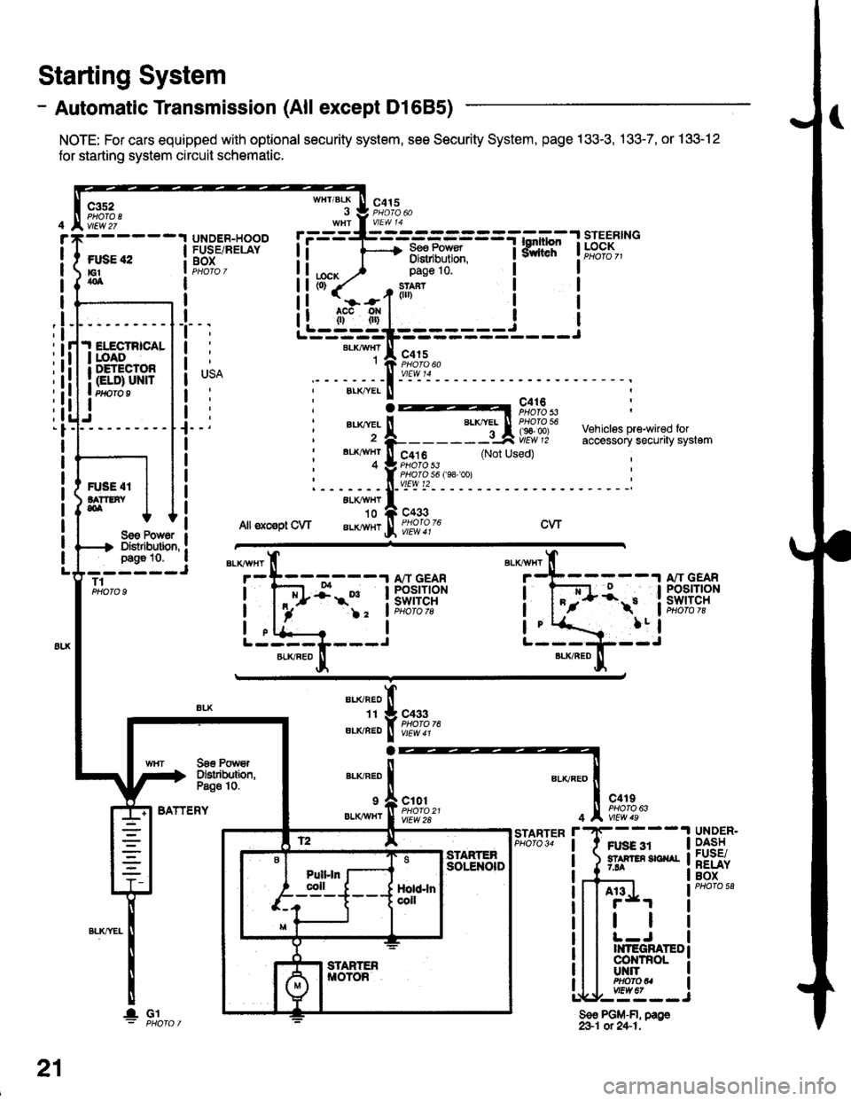
- Automatic Transmission (All except Dl685)
NOTE: For cars equipped with optional security system, see Security System, page 133-3, .133-7, or 133-12
for starting system circuit schomatic.
Starting System
c3s2PHO|O IvlEw 27
ftxiE "2E1404
WHT/BLK
I
lta":
c415
=-mF,Uf.
--l
9,lLT i ld;f,,"-
I
I
It
I
I
I
I
I
I
I
I
pag€ 10.
slan?(ll)
c415
I
Ji.I ELECTRICALI roAoI DETECTOR
I Gt ol ulra Ptfifo I
IJ
BLKAIVHT1
ELK./YEL
au(|vEL
BL'(4I/HT
4
c416PHOTO 53
c4t 6PHO|O 53PHO|O 56 f98 '�oo)vtEw t2
c433
Vehiclss pre-wired foraccessory securaty system(Not Used)
R'SE 4IlA??tNY,olALXAVHY'10
Allsxcsptow aLKlvHrcwSoe Pow6r IDistibution, !page 10. a- ----JT1PHOTO 9
BATTERY
BLKAVHT
7
L-----L---JBLKFED
13:;-1ifl;ft?R
!-
)2 'lPHoto tg
a
BLI(RED
1I
ELIVBED
ALKNED
c433PHOTO 76
Soe PowrDslributbn,Pa€o 10.
9 a c101
er.xiwxr I ffo,rtfl'�t
c4rIPHO|O 63
Ft gg 3r5? F En 3E ^r7.94
4
r'STARTERPHO|O 34UNDER.DASHFUSE/RELAYBOX
A13
tl
II{TEGRATEDco|{TnoLUT{ITPHOfOUvtEw 67,--==--J
Sso PGM-FI, page&1 ot 24-1.
21
lGl
Page 1876 of 2189
- Automatic Transmission (D1685)
c352
vtEw27
FUSE 42tGtao
.I ELECTRICALI LOADr DETECIOn
| (ELD) uNtrI PHOTO 9
I
UNDER.HOOOFUSE/RELAYBOX
r=-----L-_-_-_-_-_-=_-_-Tl.*1"","1#"Ei]""
li F 3,"j,[',ul
WHT/BLK
. J 9,1'3.WHt a V|EW 14
tcx,^ ) Page 10'
PHOTO 76
1--*---''!N"t- \o3bz7
See PowerDistribution,page 10.
c433
ALKRED4
r-^==.1
Stadorcontrol
POWERTRAINCONTROLMODULE (PCM)
c101
vtEw 28
ll
"'{----1iLi.' | |
Li-gl{l======i---i
"i*-iIr-m'
:il
See PowerDistribdion,Page '10.
".u,"if---'
-,*! s#;:{"
BLKAVHT N V/EW a t
STARTERCUTFELAYPHO|O 129
(99100)
A"/T GEARPOStTtONswrTcH
See PGlr-Fl,page 25.
STARTER
c419
FUSE 31STAffER Src{AI7.54
UNDER-DASHFUSE/NELAYBOX
BLKREO
11
"'-";;tr
A't 3
BATTERY
21-1
Page 1877 of 2189
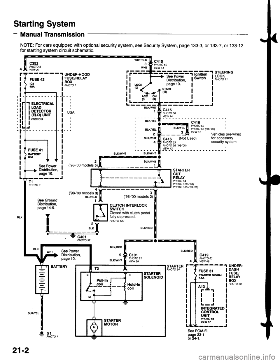
- Manual Transmission
NOTE: For cars equipped with optional security system, see Security System, page 133-3, or 133-7, or 133-12
for starting system circuit schematic.
Starting System
c3s2PHOTA 8vtEw 27
WHT/BLKc415
FUSE 42to!a0a
UNDER-HOODFUSE/RELAYBOXI
I
I
_l
IELECTBICALIOADDETECTOR(ELO) UN|TPtloro I
Sae Po'/Y€rDislibution,pag€ 10.------JT1
Se6 GroundDislribution,page 14-6.
BATTERY
STARTERCUTRELAY
PHO|A 129198)PllO|O r35 f99 00)
a
BLK/FED
9
BLKAVHT
ct01
vlEW 2A
c4't9
vtEw 49
FUSE 31STAATER SICIIAL7.5A
STARTER
4
Sse PGM-FI,page 231ot 2+1.
UNDER-DASHFUSE/RELAYBOX
At3
tl
tl
INTEGRATEDcol{tRoLut{llPHO|O U
r.------T-------------=;-*^:-lsrEERtNG
I i 1'----> R*.|?xf: iiiliffi' t"t%?I,,I Distribulion.1j;cx y' page 10.(0)
it-jtr'tl i
j
r---_-_€rx^,:jF;f
;-;:.==:t A r,+lo'tii:,J?"""
;--;*;.-f -- ^.:---.---1--
,'rr-'OO .o0"," 3,rffiEj,
---;;;;i[
cLUrcH TNTERLOCK tClosed wrlh clutch pedal Ifully depressed. llPHoro 1ra I"**"
!
Se€ PowerDistibution,page 10.
4('98100 models 3)ALU/BLK
f2 lE--r.---?q_l srAFrEn
21-2
I- G1
Page 1878 of 2189
Charging System
See PowerDistribution,pag6 10.
UNDER-HOODFUSE/RELAYBOX
FUSE 15ALT€IIIAIONsP SEII|SOF7.5A
I
t
USA
' BLKAVHTBLKI"VI/HT
-)l,------J
vtEw 50
See PowerDistribution,page 10-5.
* = 96-98rAllmodelsexcept 01685'99 '00: D16Y5 withi.4/T** = '96'�98: All models'99r00: D16Y5 witht\4/T, D1685
BATTERY
ALTERNATOR
See PowerDiskibution,page 10.
FUSE 41BATTEFY804
T101
L-----
ELECTFICALLOADDETECTOR(ELO) UNIT
'l
;l
:l
:l;l
:l
tl,l
:l
:l
G1!
- -I POWER-I -. ^ "'.1 , I rnlrn or
(.A1e)Y '('� C17)c2[ : cs
i ELD unit input i ietCrHe! ' ! coNrRoLI I MODULEI Art€rnator : lllerlato.r I (PCM or
i controrsrsnar i t",fl?il"' a:"^y]L- ----,1- - - - J Pq_oro 3'
*. B,'"',1; :.i
i:1E15_'_
_. i
GFN/FED
r i6
GFN/RED
A30
f D16)WHT/REO*Fi
See Ground IDistribution, Ipage 14-5. I
YT
L]
' ""- PHA|O
,.^;?f, :('c;3)T BLXYEL
I i 'r", ".o II'HT/ ll ' U,zscnrl :-' oi .l
, L : (c'r9ill-_- 'c11" 2)u
l9nitionrnput
LOaO
Ground ourpur
22
Page 1889 of 2189
![HONDA CIVIC 1999 6.G Workshop Manual POWERTRAIN TFUSE 15AtTEii|AtOf, ^ -aPsE|{aon see Fowert5a ^ Distribution,99coldary---]-l-"jt=-.iHO2S iinBt
E*o,*. !CONTROL IMODULE I(PCMoTECM) :i,l,llouu riI
\T,T]KDT4
WHT/NEDBLKAVHT
1
T
t
WHI/FED
I HONDA CIVIC 1999 6.G Workshop Manual POWERTRAIN TFUSE 15AtTEii|AtOf, ^ -aPsE|{aon see Fowert5a ^ Distribution,99coldary---]-l-"jt=-.iHO2S iinBt
E*o,*. !CONTROL IMODULE I(PCMoTECM) :i,l,llouu riI
\T,T]KDT4
WHT/NEDBLKAVHT
1
T
t
WHI/FED
I](/manual-img/13/6068/w960_6068-1888.png)
POWERTRAIN TFUSE 15AtTEii|AtOf, ^ -aPsE|{aon see Fowert5a ^ Distribution,99coldary---]-l-"jt='-.iHO2S iinBt
E*o,*. !CONTROL IMODULE I(PCMoTECM) :'i,l,llouu riI
\T,T]KDT4
WHT/NEDBLKAVHT
1
T
t
WHI/FED
IT GFN
c130Oermlnals1n0)
vtEw 52
')------------6;ffii----F'�di---:-- ----Ttgy.:!-
{ Strff' .'Sffi"? .uoFo?,* | su #33nno' ruo'ffiJ,. srouno i6is-*' #;,"1"-* ' canistqvent sotenoid l":iiEt$'[i,
i ffii$J' *H*"n' i :3Hl'5'* varvaclntror,llg'r+,.'
I . -__-,__-SJECM)fL------ Prloro a6
t
UNDER.DASHFUSE/RELAYBOXPHOTA 58
BLKAVHT
1I'j
c101
vtEw 2a
_{
rn+5-m
. c115, Oermlnals,'t-71
I vtEw 38
c401
c568
VIEW 4
ALKAVHT
BLKAVHT
,l
See Pow€rDistribution,page 10.5.
EVAPORATIVEEMtSStON(EVAP) PURGECONTROLSOLENOIDVALVE
EVAPORA. 'TIVEEMtSStON '
(EVAP) :BYPASS iSOLENOID ,VALVEEvaponn- 2
TIVEEMtSStON(EVAP)CONTROLCANISTERVENT SHUTVALVEPHATO 39
c125
BLU
1
BFN/BLK
'97 model:Calilornia Coupe,Calilornia Sedan LX'98 modei: all
c568
c401
c131
vlEw 59
Ses GrourdDisMbdion,pag€ 14-1.
NEO/YELBLKNVHT
D13A5
FED,^VEL
A15
LT GFNAIVHTT1
G101PHO|Q 33M8
BIK/YEL
r+l
23-9
Page 1899 of 2189
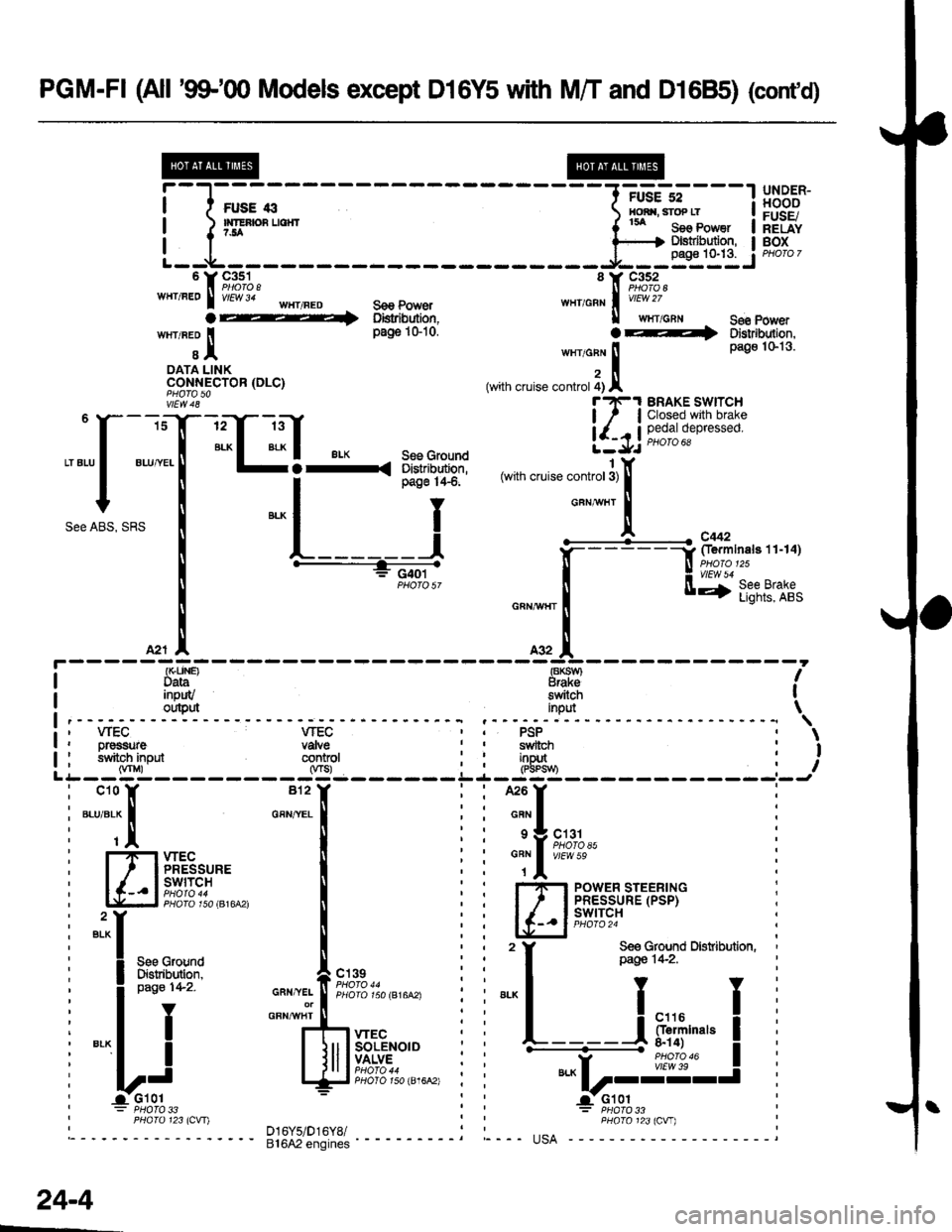
PGM-FI (All '9$"q) Models except D16Y5 with M/T and D1685) (cont'd)
@@
i-l;;--
----1-:::=*"---l
!,8,:"ff
| )'rEnsuorr ( tu seo Power I hEiiY
'r9,1%, 'r F,1%,wHr/FEo I v/El/v 34 'HT/FED s€e power w111,6s1 | vtew zz
a 1 oistribution, ll wrlcnr See power
wrr neo I pa$iGio. OF+ DstnbJtron.
t I tn"to"n ! Pa9o 1s13'
oAra LINK z llCONN-ECTOR (DLC) (with cruise controt 4) A
vtEw 48 t?e1 BRAKE SWTTCH
isT-rrT ltf !1.l'".e'.l;'[3J:5:
""[ ":T-:"C-l:.Frd*Fl
lll,
"""f "",T
""U]-t-.,-t-..*.",,""*^i:# [*iu'r;i:;r.';
'""o1""1 ""l
l ;f=:&ri'n"*,,.,0r
[
.---+_s,:.;-,
"*,**il [ff'ftrs,llr,
*,.!. ^* IA2r |' A32 A
: {r(LlN€) €KSW} |I Data Braksfleu.rt} ft svyl IData Braksinpuv switch Ioutput inpd \\' wEC VTEC PSP
I PHaro 123lcvr) D16y5/Dr6y8/ : : PHoro 123lcw)
---'- ei6A2'"noin"i ---- "--- usA
;
L
Dr€ssure vaNesrlitoh input conkol(Vnr) 0rs)
*{
---
"::l
fTlxlE8,u,. I
lc-- ll#il?i,",,*, I
"il
II see crouno
! Fi"frW """,*f,f,',11,r,",.*,
-'l
I
""""iJ,,.lff*u"'"
yi qr;;;i6;;o,E.6A',
: PHOTO 33
sYvltctlinDut
---u-r----
can I
s I crer
"Tl t#ffl","
I-'I-I POWER STEERINGI ' I PRESSURE (PSP)
lc_.ltg+I9i
,
f ff&G{lfd Drsribution,
""L----i
F*i,""," I.----a- -r*ro_*
|"," I vtEw 39
Lr----J
: PHATO 33
\
I
I
pag€ 142.
24-4
Page 1945 of 2189
- How the Circuit Works
The anti-lock brake system (ABS) prevents locking
of the wheels as a result of heavy braking and/or
poor lraction. A vehicle with locked wheels cannot
be steered. The anti-lock brake system controls the
application of the brakes, allowing the driver to
maintain control of the steering.
Under anti-lock conditions, the antilock brake
system (ABS) modulates the pressure of the brake
tluid to each brake caliper. This system is a four
channel system: the pressure at each caliper is
controlled independently of the pressure al any
other caliper. Whenever a wheel is likely to lock
dunng braking, the anti-lock brake system
modulates the brake oressure at that wheel. When
the brake pressure is reduced to the point where
there is no longer any possibility of wheel locking,
the system returns to the conventional braking
system mode of operation.
Battery voltage is applied at all times through fuse
63 to the ABS control unit. When the ignition switch
is in ON (ll), battery voltage is supplied to the
control unit through fuse 16. The control unit is case
grounded. Inputs are received from the brake switch
and the individual wheel sensors located at each
wheel. The ABS control unit uses these inputs to
control the modulator solenoid unit. The solenoids
adjust the hydraulic pressure applied to each
calioer.
The ABS control unit has a self-diagnosis function.
When the control unit detects a fault, it turns on the"ABS" indicator and disables the anti-lock brake
system. lf the fault is not in the conventional braking
system, the brakes will continue to operate normally
but without the anti-lock feature.
Refer to the Service Manual (Section '19,
Anti-Lock Brake System) for specific tests or
troubleshooting procedures.
44-3