Page 1496 of 2189

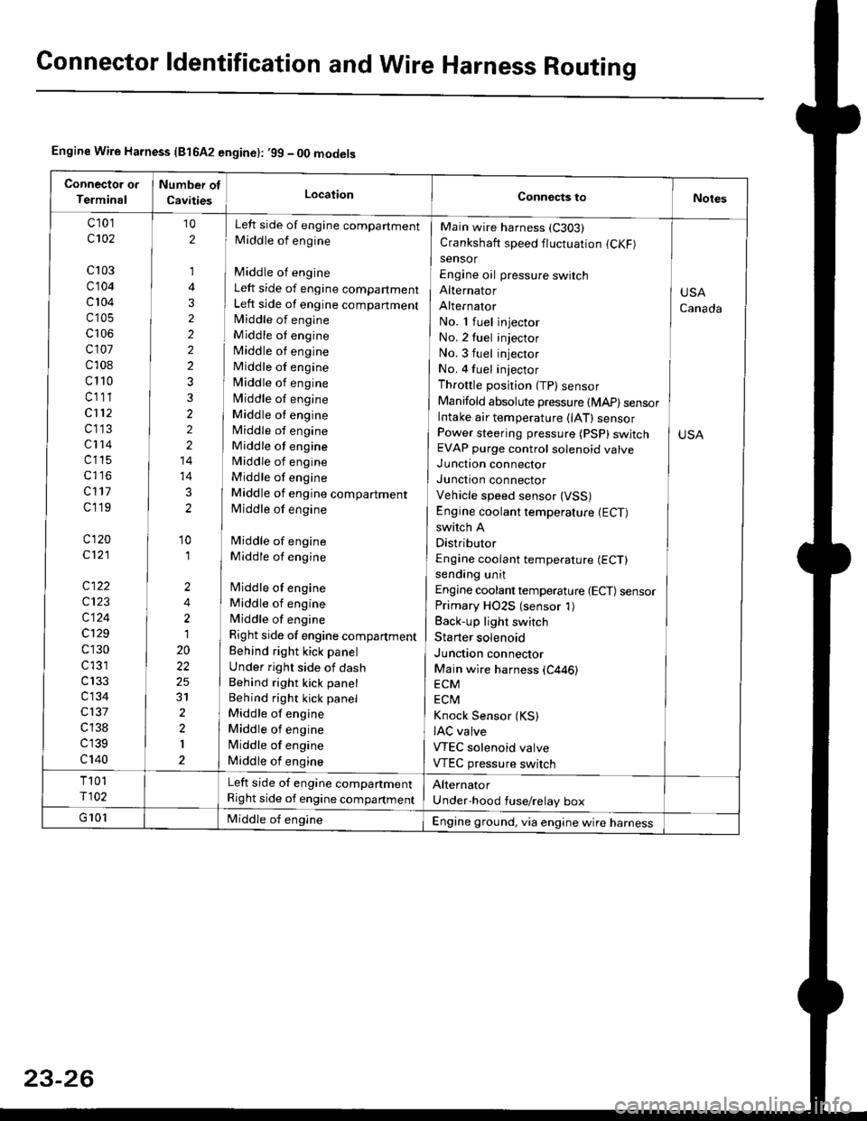
Connector ldentification and WireHarness Routing
Engine Wire Harness {81642 engine}: .99 - 00 models
c 101
c102
cl03
c104
c 104
c'105
c106
cl01
c108
c110
cl11
cl12
c1'13
c114
c115
c117
cl19
c120
c121
c122
c123
c124
c129
c130
c l31
c133
c134
c137
c 138
c139
c140
Left side of engine companment
Middle of engine
Middle of engine
Left side of engine compartment
Left side of engine compartmentlvliddle of engine
Middle ot engine
Middle of engine
Middle of engine
Middle of engine
Middle of engine
Middle ot engine
Middle of engine
Middle of engine
Middle of engine
Middle of engine
Middle of engine compartment
Middle of engine
Middle of engine
Middle of engine
lMiddle of engine
Middle of engine
Middle of engine
Right side of engine compartment
Behind right kick panel
Under right side of dash
Behind right kick panel
Behind right kick panel
Middle of engine
Middle ot engine
lMiddle of engine
Middle of engine
10
2
,]
4
3
2
2
2
2
3
3
2
2
2
14
14
3
2
'10
'I
2
4
2
1
20
22
25
31
2
2
I
Main wire harness (C303)
Crankshaft speed fluctuation (CKF)
sensor
Engine oil pressure switch
Alternator
Alternator
No. 1 fuel injector
No. 2 tuel injector
No. 3 fuel injector
No. 4 fuel injector
Throttle position (TP) sensor
Manifold absolute pressure (MAP) sensorIntake air temperature (lAT) sensorPower steering pressure (PSP) swjtchEVAP purge control solenoid valve
Junction connector
Junction connector
Vehicle speed sensor (VSS)
Engine coolant temperature (ECT)
switch A
Distributor
Engine coolant temperature (ECT)
sending unit
Engine coolant temperature {ECT) sensorPrimary HO2S (sensor 1)
Back-up light switch
Starter solenoid
Junction connector
Main wire harness (C446)
ECM
ECtvl
Knock Sensor {KS)IAC valve
VTEC solenoid valve
VTEC pressure switch
USA
Canada
Left side of engine companment
Right side of engine compartment
Engine ground, via engine wire harness
Page 1533 of 2189
(l'-
Fuse NumberAmpswire ColorComponent(s) or Circuitlsl Protect€d
4180APower distribution
4240AWHT/BLKTo ignition switch (BAT)
437.5 AWHT/REDCeiling light, data link connector, trunk light
4415 AWHT/BLKPGM-Fl main relay
Not used
4640AWHT/BLUPower window motors (via power window relay)
477.5 AWHT/BLUAudio unit, clock, TCM (CVT), ECM/PCM (VBU)
4830AWHTNo.33 (7.5 A) fuse, To combination light switch (headlight)
49Not used
5030AWHT/GRNRear window defogger (via rear window defogger relay)
cl20AWHT/GRNPower door lock control unit, moonroof motor
15 AWHT/GRNHorn system, brake lights, brake signal
10 AWHT/BLKHazard warning light, turn signal/hazard rclay
54404WHT/REDOption {+B)
5540ABLU,A/VHTBlower motor (via blower motor relay)
204WHTCondenser fan motor (via condenser fan relay)
REDl'lc compressor clutch (via IVC compressor clutch relay)
204BLVBEDRadiator fan motor (via radiator fan relay)
23-6
Page 1535 of 2189

lr-
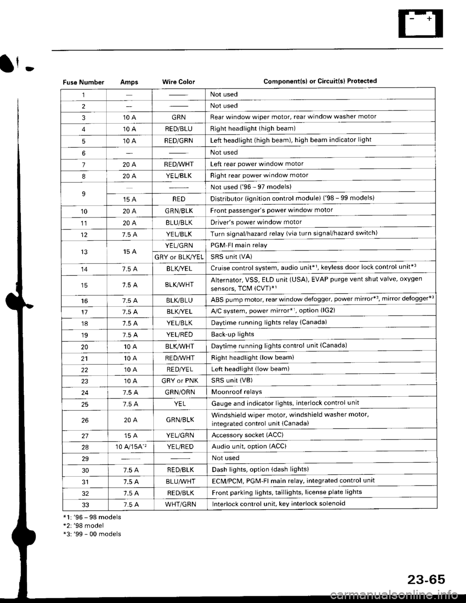
Fuse NumberAmpswire ColorComponent{sl or Circuit(sl Protected
*1r '96 - 98 models*2r '98 model*3: '99 - 00 models
,lNot used
2Not used
310 AGRNRear window wioer motor, rear window washer motor
410 ARED/BLURight headlighr thigh beam)
510 ARED/GRNLeft headlight (high beam), high beam indicator light
6Not used
7204R E D/VVHTLeft rear power window motor
820A.YEUBLKRight rear power window motor
9Not used ('96 - 97 models)
't5 AREDDistributor (ignition control module) ('98 - 99 models)
10204G RN/BLKFront passenger's power window motor
1120ABLU/BLKDriver's power window motor
127.5 AYEUBLKTurn signal/hazard relay (via turn signal/hazard switch)
t515 AYEL/GRNPGM-Fl main relay
GRY or BLK,^/ELSRS u nit (VA)
141.54B LK/YE LCruise control system, audio unit*1, keyless door lock control unit*3
BLK/lr'r'HTAlternator, VSS, ELD unit (USA), EVAP purge vent shut valve, oxygen
sensors, TCM (CVT)*'
t6BLI(,/BLUABS pump motor, rear window defogger. power mirror*3, mirror delogger*3
177.5 ABLK,/YE LA,/C system, power mirror*r. option (lG2)
18YEUBTKDaytime running lights relay (Canada)
197.5 AYEUREDBack'up lights
2010ABLK/VVHTDaytime running lights control unit (Canada)
2110 AREDA/VHTRight headlight (low beam)
2210 ARE DI/E LLeft headlight (low beam)
10 AGRY or PNKSRS UNit (VB)
247.5 AGRN/ORNMoonroof relays
257.5 AYELGauge and indicator lights. interlock control unit
204GRN/BLKWindshield wiper motor, windshield washer motor,
integrated control unit {Canada)
15 AYEL/GRNAccessory socket (ACC)
2a10 A,/'�]5A''YE L/R EDAudio unit, option (ACC)
29Not used
307.5 AR ED/BLKDash lights, option (dash lights)
1.5 ABLUA/VHTECM/PCl\4, PGM-Fl majn relay, integrated control unit
RED/BLKFront parking lights, taillights, license plate lights
337.5 AWHT/GRNlnterlock control unit. key interlock solenoid
23-65
Page 1561 of 2189

Battery
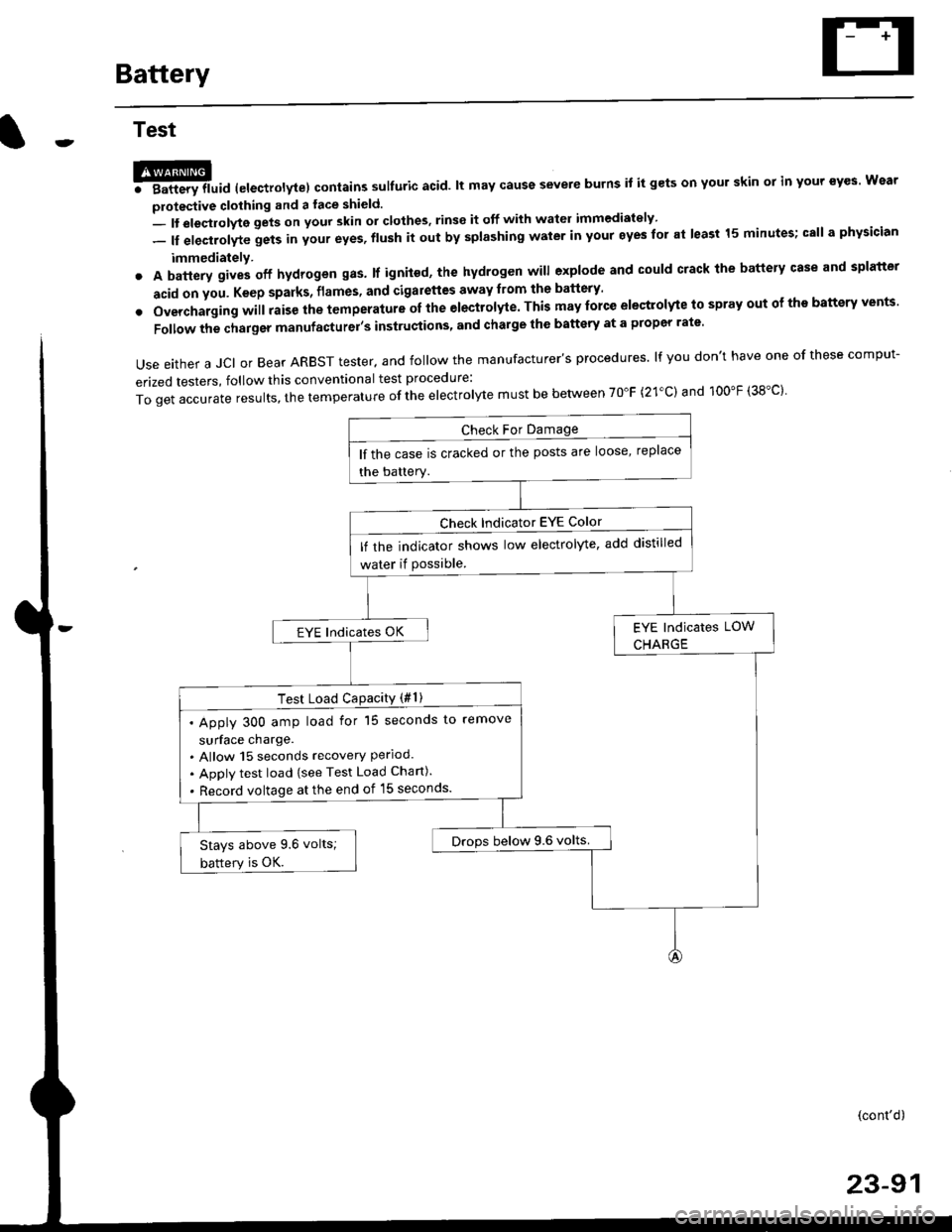
Test
@l. Battery lluid lelectrolytel contalns sulfuric acid. lt may cause severe burns it it gets on your skin ol in your eyes Wear
protective clothing and a face shield.
- It eleqtlolyte gets on your skin or clothes, rinse it off with watel immediately
- lf electrolyte gets in your eyes, flush it out by splashing water in your eyes for at least 15 minutes; call a physician
immediately.
. A battery gives off hydrogen gas. lf ignited, the hydrogen will explode and could crack the battery case and splatter
acid on you. Keep sparks, flames, and Gigarettes away from the battery'
o Overchaiging will raise the temperature oI the electrolyte. This may force electrolyte to spray out ot ths battery vents'
Follow the charger manufacturel's instrustions, and chalge the battery at a propcr rate.
Use either a JCI or Bear ARBST tester. and follow the manufacturer's procedures. lf you don't have one of these comput-
erized testers, follow this conventional test procedure:
ToqetaccurateresuIts,thetemperatureoftheeIectro|ytemustbebetweenT0"F(21.c)and100"F(38.c}'
lf the case is cracked or the posts are loose, replace
the battery.
lf rhe indicator shows low electrolyte, add distilled
water if Possible.
EYE lndicates OK
Test Load CaPacitY (#l )
. Apply 300 amp load for 15 seconds to remove
surface charge.. Allow 15 seconds recovery Perloo.. Apply test load {see Test Load Chan).
. Record voltage at the end of l5 seconds.
Drops below 9.6 volts.Stays above 9.6 volts;
battery is OK.
(cont'd)
23-91
Page 1562 of 2189
Battery
Test (cont'd)
Charge on High Sefting (40 amps)
Charge until EYE shows charge is OK; plus anadditional 30 minutes to assure full charge.NOTE: lf the battery charge is very tow, it maybe necessary to bypass the charger,s polarityprotection circuitry.
lf the EYE does not show charge is OK withinthree hours, the battery is no-good; replace it.Write down how long the battery wascharged.
Test Load Capacity (#2)
Apply 300 amp load for 15 seconds to remove surface charoe.Allow 15 seconds recovery period.
Apply test load {see Test Load Chan).
Record voltage at the end of 15 seconos.
Stays above 9.6 volts; battery is OK. ,] Drops below 9.6 volts; baftery is no-good.
tu,
TEST LOAD CHART
Use the test load or 1/2 the cold cranking amps {CCA) printed on thelabel on the top of the banery. lf neither is indicated. use theinformation below:
BArrERy coLb@
coDE I AMps (ccAl | {amps)
405 (*410)200
*:558241 (S) - MF
23-92
Page 1574 of 2189
lgnition System
Circuit Diagram :'98-00 models
UNDER HOOD FUSUFELAY BOX'x'E;;;;-;;;;l /; l-*;- Ecw.cM
ffiwFnBLK<-wHr\9-
Y
tlBTKTYEL YEUGRN
IGN]TIONswtTcHUNDER,DASHFUSE/BELAY BOX
YEt
J
BLK
J
FED
+
*1 :H TACHI*2 :TEC
9 *IBLU'
23-104
Page 1578 of 2189
lgnition System
Distributor Overhaul (cont'dl
TEC:
IGNITION CONTROLMODULE IICM'Input Test, page 23-1
DISTRIBUTOR IGNITION {DI} HOUSINGCheck for cracks and damage.
COVER
DISTRIBUTOR IGNITION IDI) ROTOB
CAP SEALCheck for damage.DISTRIBUTOR IGNITION {DII CAPCheck for cracks, wear,damage, and fouling.Clean or replace,
IGNITION COILTest, page 23-110
O-RINGReplace
\
I
@
TDC/CKP/CYP S€NSORTroubleshooting, section 1 1Do not disassemble.
WHT/BLU
23-104
Page 1579 of 2189

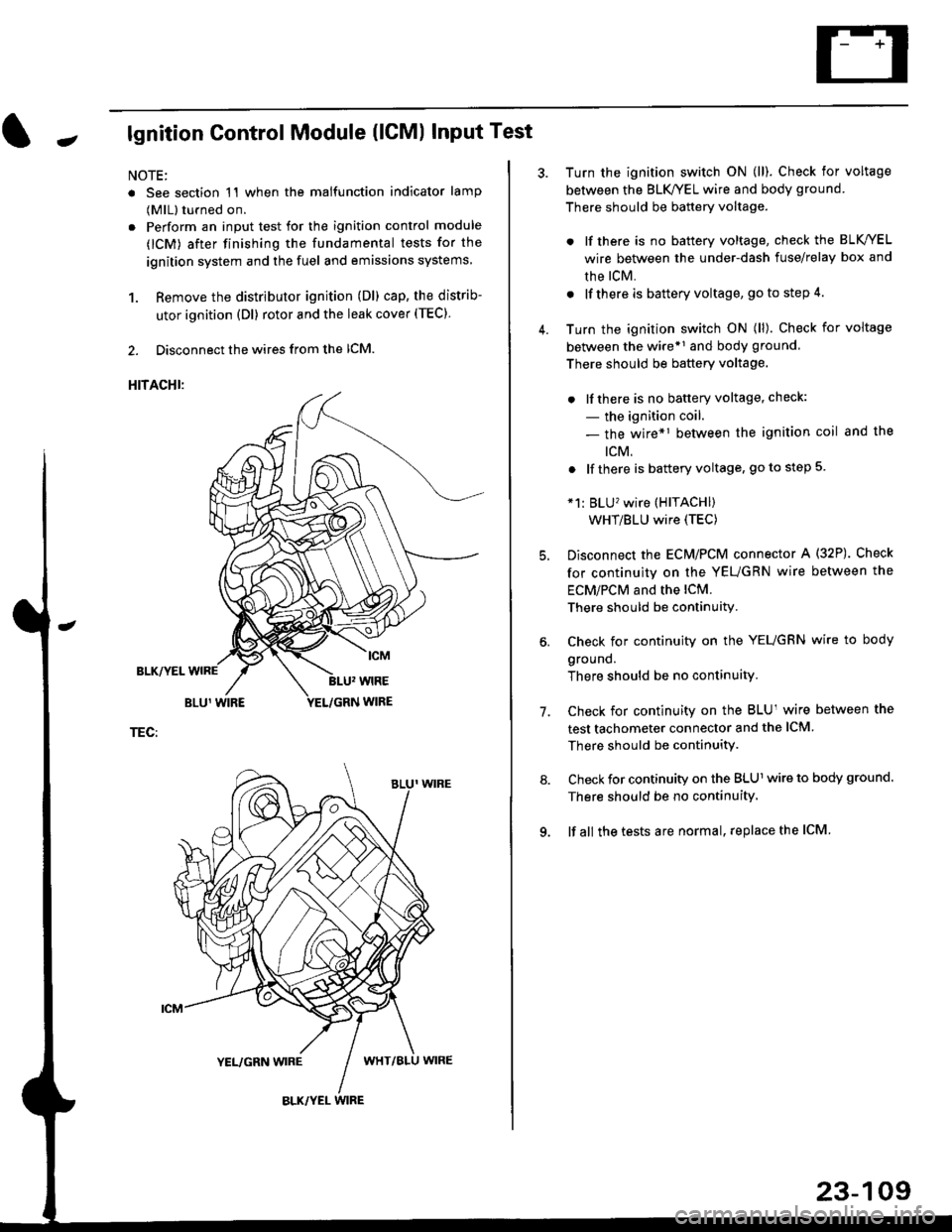
Jlgnition Control Module (lCMl Input Test
NOTE:
. See section 1'l when the malfunction indicator lamp
(MlL) turned on.
. Perform an input test for the ignition control module
(lCM) after finishing the fundamental tests for the
ignition system and the fuel and emissions systems
1. Remove the distributor ignition (Dl) cap, the distrib-
utor ignition (Dl) rotor and the leak cover (TEC).
2. Disconnect the wires from the lCM.
HITACHI:
BLK/YEL
TEC:
Turn the ignition switch ON (ll). Check for voltage
between the BLK/YEL wire and body ground.
There should be battery voltage.
. lf there is no battery voltage, check the BLK/YEL
wire between the under-dash fuse/relay box and
rhe lcM.
. lf there is battery voltage, go to step 4.
Turn the ignition switch ON (ll). Check for voltage
between the wire*r and body ground
There should be battery voltage.
. lfthere is no battery voltage, check:
- the ignition coil.
- the wire*1 between the ignition coil and the
tcM.
. lf there is battery voltage, go to step 5
*1: BLU'�wire (HITACHI)
WHT/BLU wire (TEC)
Disconnect the EcM/PCM connector A (32P). Check
for continuity on the YEUGRN wire between the
ECM/PCM and the lCM.
There should be continuity.
Check for continuity on the YEUGRN wire to body
ground.
There should be no continuity.
Check for continuity on the BLUl wire between the
test tachometer connector and the ICM
There should be continuitY.
Check for continuity on the BLUl wire to body ground.
There should be no continuity.
lf all the tests are normal, replace the ICM
7.
23-109