Page 1287 of 2189

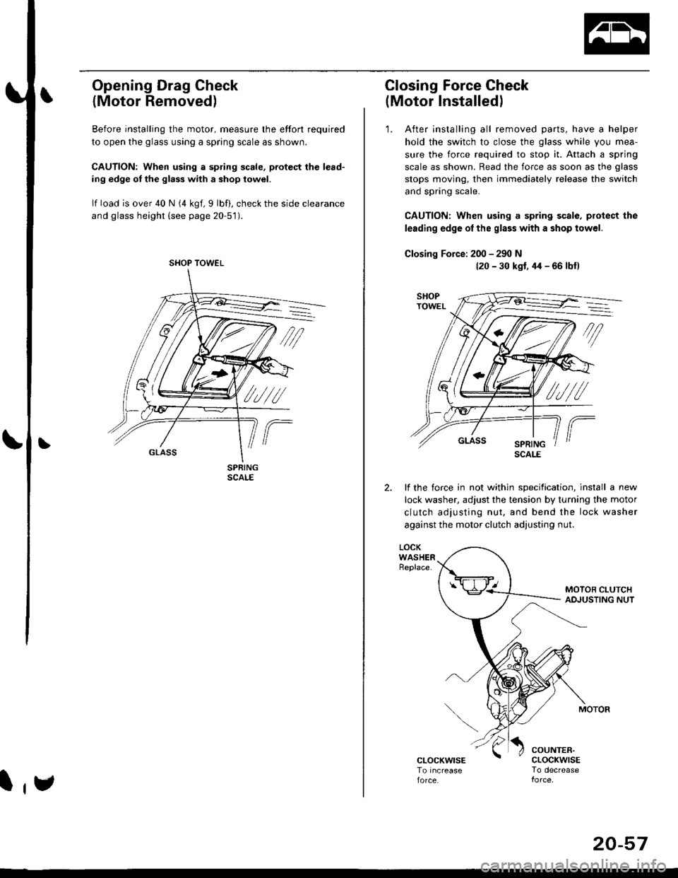
Opening Drag Check
{Motor Removed)
Before installing the motor, measure lhe effort required
to open the glass using a spring scale as shown.
CAUTION: When using a spring scale, pfotest the lead-
ing edge ol the glass with a shop towel.
lf load is over 40 N (4 kgf,9 lbf), check the side clearance
and glass height (see page 20-51).
SHOP TOWEL
l,e
20-57
Closing Force Check
(Motor Installedl
'1. After installing all removed parts, have a helper
hold the switch to close the glass while you mea-
sure the force required to stop it. Attach a spring
scale as shown. Read the force as soon as the glass
stops moving, then immediately release the switch
and spring scale.
CAUTION: When using a spring scale, protect the
lerding edge ol the glass with a shop towel.
Closing Force: 200 - 290 N(20 - 30 kst, 44 - 66 lbfl
lf the torce in not within specification, install a new
lock washer, adjust the tension by turnang the motor
clutch adjusting nut, and bend the lock washer
against the motor clutch adjusting nut.
LOCKWASHERReplace.
COUNTER.cLocKwrsETo decrease
SCALE
Page 1289 of 2189
Interior Trim
tReplacement
CAUTION:
. Put on gloves to protect your hands.
o When prying with a flat-tip screwdriver, wrap it with protective tape to prevent damage.
NOTE: Take care not to bend or scratch the trim and panels.
4D:
>: Clip locationsa>,2c >,2'lo >,2E >,2
r*'" n t-lt't
\wi, i
' l ll/
_tr* @,
CENTER PILLARUPPER TRIMREAR PILLARTRIM
LOCK CYLINDER TRIM
tl'
I
E'vBELT UPPERANCHOR(see page 20-85)
Disconnect thehigh mount brakelrght connector.
T SIDE TRIMRemove the rear seat cushion and rearseat side bolster lsee page 20-19]'.
)
lnstallation is the reverse of the removal procedure.
NOTE:
. lf necessary, replace any damaged clips.. Before installing the front seat belt upper anchor
and rear shelf. make sure there are no twists or
kinks in the seat belts.(cont'd)
B>,6
REAR SHELF
k"si
fEFT KICKPANEL
20-59
Page 1290 of 2189
lnterior Trim
Replacement (cont'dl
3D:
>: Clip locationsA>,2CLIP
N;
nt-.l I'"'\R
I
")!
F >, lil
TRIM
B>,3
G >,2H>,2
t
FRONT SEATBELT UPPEBANCHORlsee page 20 86)
SIDE TRIM PANELPROTECTOR
LEFT KICKPANEL
c >,8o>,3
PIVOT BRACKET
{see page 20-80)
lnstallation is the reverse of the removal procedure
NOTE:
. lf necessary, replace any damaged clips'
. Before installing the anchor bolts, make sure there
are no tlvists or kinks in the seat belts'
E >,8
>: Screw, bolt locationsA>,3 8>,6
^l l-lEF\
#, A@ Y
*"0
c>, 1
I "4"
\s
o >,2
l@@
\---
s,4, ffi;T
FRONT PILLARB
eV
REAR SIDESHELF
SIDE TRIMPANELRemove the rear seat-back and
rear seat cushion (see Page 20_80)
Disconnect the rear speaker
connector (both sides,
for some models).
REAR TRIMPANEL
q
RIGHT KICKPANEL
"x-
20-60
Page 1292 of 2189
Trunk Trim
Replacement
CAUTION:
. Put on gloves to proteci your hands.
. When prying with a flat-tip screwdriver, wrap it with protestive tap€ lo prevent damage.
NOTE:
. Take care not to bend or scratch the trim and panels.
. When removing the trunk side trim or trunk trim panel, fold the seat-back forward.
Japan-produced:
4D: RIGHT TRUNKSIDE TRIM
TRUNK MAT
1B
REAR TRIMPANEL
>: Clip locationsa>,6
a:-) ,2
I g cLlP ^
l#srq-'
| ' |NNER\- crLP
B >,6
NOTE: Do not push
the inner clip in too far.
IJ
LTro
i ) :Hook locations
A i--) , r
' 2D:
TRUNK TRIM
Installation is the reverse of the removal procedure.
NOTE:
. lf necessary. replace any damaged clips.
. To install the A clips. pull the inner clip up. install
the clip, then push the inner clip until it's flush.
(
,- --
/'/ \--
/ --
20-62
Page 1293 of 2189
Hatch Trim
>:Clip locationsa>,2NOTE: Do not push thlnner clip in too far.
& ct-tp.
54d-g+-\
2. INNF
Ijy. "
\
.V ft -s---
- k-"i-t-;-a-
Replacement
CAUTION:
. Put on gloves to protect your hands.
. When prying with a flat-tip screwdrivel, wrap it with protestive tape to prevent damage.
NOTE: Take care not to bend or scratch the trim and panel.
LEFT HATCHSIDE TRIM
HATCHUPPER TRIM
Installation is the reverse of the removal procedure.
NOTE:
. lf necessary, replace any damaged clips.
. ToinstalltheAclips,pulltheinnerclipup.installtheclip,thenpushtheinnerclipuntil it'sflush
a
I
20-63
Page 1298 of 2189

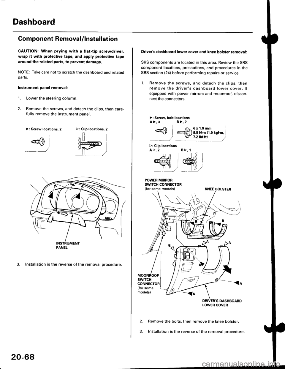
Dashboard
Component RemovaUlnstallation
CAUTION: When prying with a flat-tip screwdriver,
wrap it with protoctivo tape, and apply protective tape
around tho r6lat6d parts, to prevent damag6.
NOTE: Take care not to scratch the dashboard and relatedpans.
Instrument Danel removal:
1.Lower the steering column.
Remove the screws, and detach the clips, then care-
fully remove the instrument panel.
3. Installation is the reverse of the removal procedure.
>: Clip locations, 2
.il |
Pit)_ _ ,/
>: Screw locations,2
^l
@sl
:)
PANEL
20-68
Driver's dashboard lower cover and knee bolster removal:
SRS components are located in this area. Review the SRS
component locations, precautions. and procedures in the
SRS section (24) before performing repairs or service.
'1. Remove the screws, and detach the clips, then
remove the driver's dashboard lower cover. lf
equipped with power mirrors and moonroof, discon-
nect the connectors.
>: Screw, boh loc.tionsA>.3B>,2
_-rri I /a_6x1.0mm*\Y @{[) s 8 N'm tt o rst'm,
_-_- J _ \J- 7 2_rbtftl -_
>: Clip locationsA>.2 B >, 1
tu
DRIVER'S DASHBOARDLOWER COVER
Remove the bolts, then remove the knee bolster.
Installation is the reverse of the removal procedure.
Page 1304 of 2189
Front Seat
Removal
CAUTION: When prying with a flat-tip screwdriver, wrapit with protective tape lo prevent damage.
NOTE: Take care not to scratch the seat covers and body.
1. Remove the seat track end cover, then remove thebolts.
SEAT TRACKCOVER
FRONT SEAT
)
SEAT TRACKEND COVER
BOLT8 x'1.25 mft22 N..n 12.2 kgl.m,16 rbf.ft)
8 x 1.25 mm22 N.rn 12,2 kgl.m,16 tbtft)
20-74
2. Lift the driver's front seat, then disconnect the seatbelt switch connector.
SEAT BELTswtTcHCONNECTOR
4.
Remove the headrest.
Carefully remove the front seat through the dooropening.
Installation is the reverse ol the removal procedure.
NOTE: Make sure the connector is connected prop-
erry.
5.
Page 1305 of 2189
Replacement
CAUTION: When prying with a flat-tip screwdrivet, wrap it with protective tape to prevent damage'
NOTE:
. Take care not to scratch the seat covers and body
. Remove the front seat through the door openlng'
Driver's:
NOTE: Refer to page 2O-77 for the seat belt switch harness wiring location'
SEAT CUSHION
CENTER COVER
INNER SEATTBACK
PIVOT NUT8 x 1.25 mm22 N.m l.2.216 tbf.ft)
v
l
35 tbt.ft)
10 x 1.25 mm47 N.m {4.8 kgf m,10 x 1.25 mm47 N.m {i1.8 kgl m,35 tbr.ft)
RECLINE ADJUSTER
LOW
d
ER CAP
l
RECLINE
CONNECTING WIRETo connect, twist 180'
OUTER SEATTRACK
Installation is the reverse of the removal procedure'
NOTE:
. Make sure the bushing and pivot washer
installed ProPerly.. To prevent wrinkles when installing the seat-
back cover, make sure the material is stretched
evenly over the Pad.
. Grease the sliding Portion
8 x 1.25 mm20 N.m 12.0 kgf.m,14 tbt.ft)
are
RECLINEKNOB
(cont'd)
20-75
10 x 1.25 mm47 N.m {4.8 kgf'm,35 tbtftl