Page 1580 of 2189

lgnition System
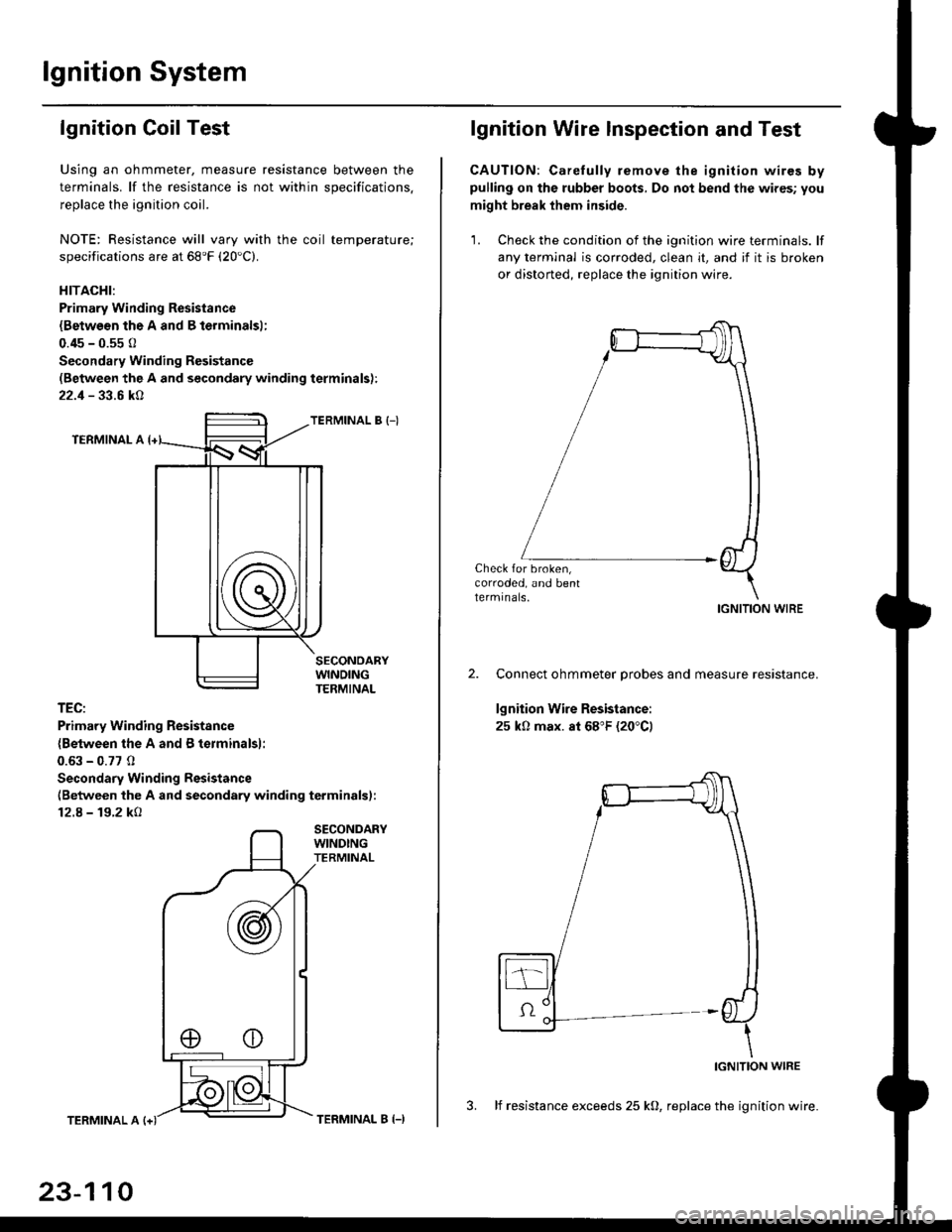
lgnition Coil Test
Using an ohmmeter, measure resistance between the
terminals. lf the resistance is not within soecifications.
replace the ignition coil.
NOTE: Resistance will vary with the coil temperature;
specifications are at 68'F (20'C).
HITACHI:
Primary Winding Resistance
{Betwesn the A and B lerminalsl;
0.45 - 0.55 0
Secondary Winding Resistanc€
(Between the A and secondary winding terminals):
22.1 - 33.6 kA
TERMINAL B {-)
TERMINAL A
TEC:
Primary Winding Resistsnce
{Between the A and B terminalsl:
0.63 - 0.77 0
Secondary Winding Resistance
(Between the A and secondary winding terminals):
12.8 - 19.2 kO
SECONDARYWINDINGTERMINAL
TERMINAL A
23-110
TERMINAL B (-)
lgnition Wire lnspection and Test
CAUTION: Carelully remove the ignition wires bypulling on the rubber boots, Do not bend the wires; you
might break them inside.
'1. Check the condition of the ignition wire terminals. lf
any terminal is corroded, clean it, and if it is broken
or distorted, replace the ignition wire.
Check for broken,corroded, and bentlermrnals.IGNITION WIRE
Connect ohmmeter probes and measure resistance.
lgnition Wire Resistance:
25 k0 max. at 68"F (20"C)
IGNITION WIRE
3. lf resistance exceeds 25 kO, replace the ignition wire.
Page 1582 of 2189
Charging System
Component Location Index
UNDER.HOOD FUSE/RELAY BOX/*Has replaceable ELECTRICAL LOAD II DETECTOR (ELD) UNIT '
Troubleshooting, page 23-1 14Replacement, page 23-120Bectifier Removal, page 23,121Rectifier Test, page 23-122Rear Bearing Replacement, page 23-j24
*ELD unit: USA
CHARGING SYSTEM LIGHT(ln the gauge assembly)Test, page 23- l14
BATTERYTest, page 23-91
ALTERNATOR BELTInspection and Adjustment, page 23-t25
[]
23-112
Page 1605 of 2189
JRemoval
1. Remove the two screws from the instrument panel.
2. Remove the instrument panel.
CAUTION: Carefully remove the instrument panel without damaging the clips.
3. Tilt the steering wheel down with the tilt adjustment lever.
4. Spread a protective cloth over the steering column.
5. Remove the four mounting screws from the gauge assembly.
6. Pry the gauge assembly out, and disconnect all connectors from it
7- Take out the gauge assembly.
GAUGE ASSEMBLY
INSTRUMENT PANEL
23-135
Page 1610 of 2189
Vehicle Speed Sensor (VSSI
Troubleshooting
Before testing, inspect the No. 15 (7.5 A) fuse in the under-dash fuse/relay box.
TEST HARNESSOTLAJ _ PT3O2OAREO TEST HARNESSCLIP
PROTECTIVETAPE
TEST HARNESSOTLA' . PT3O2OA
(To next page)
Test the BLK wire:1. Disconnect the 3P connectorfrom the vehicle speed sensor(vss).
2. Connect the test harness(07LAJ PT30200) only to theengine wire harness,3. Connect the RED test harnessclip to the positive probe of a
4. Check for continuity betweenthe RED test harness clip andbody ground.
Repair opon in the BLK wireb€twe€n the VSS and G101.ls there continuity?
Te3t the BLK/YEL wire:1. Connect the WHT test harnessclip to the positive probe of avoltmeter, and connectthe REDtest harness clip to the negativeprobe.2. Turn the ignition switch ON {ll).
Repair open in iho BLK/YEL wirebetween the VSS and the under-d6sh tuse/relav box.
vss
GRN TEST HARNESS
RED TEST HARNESS
WHT TEST HARNESS CLIP
23-140
Page 1611 of 2189

J
(From prevaous page)
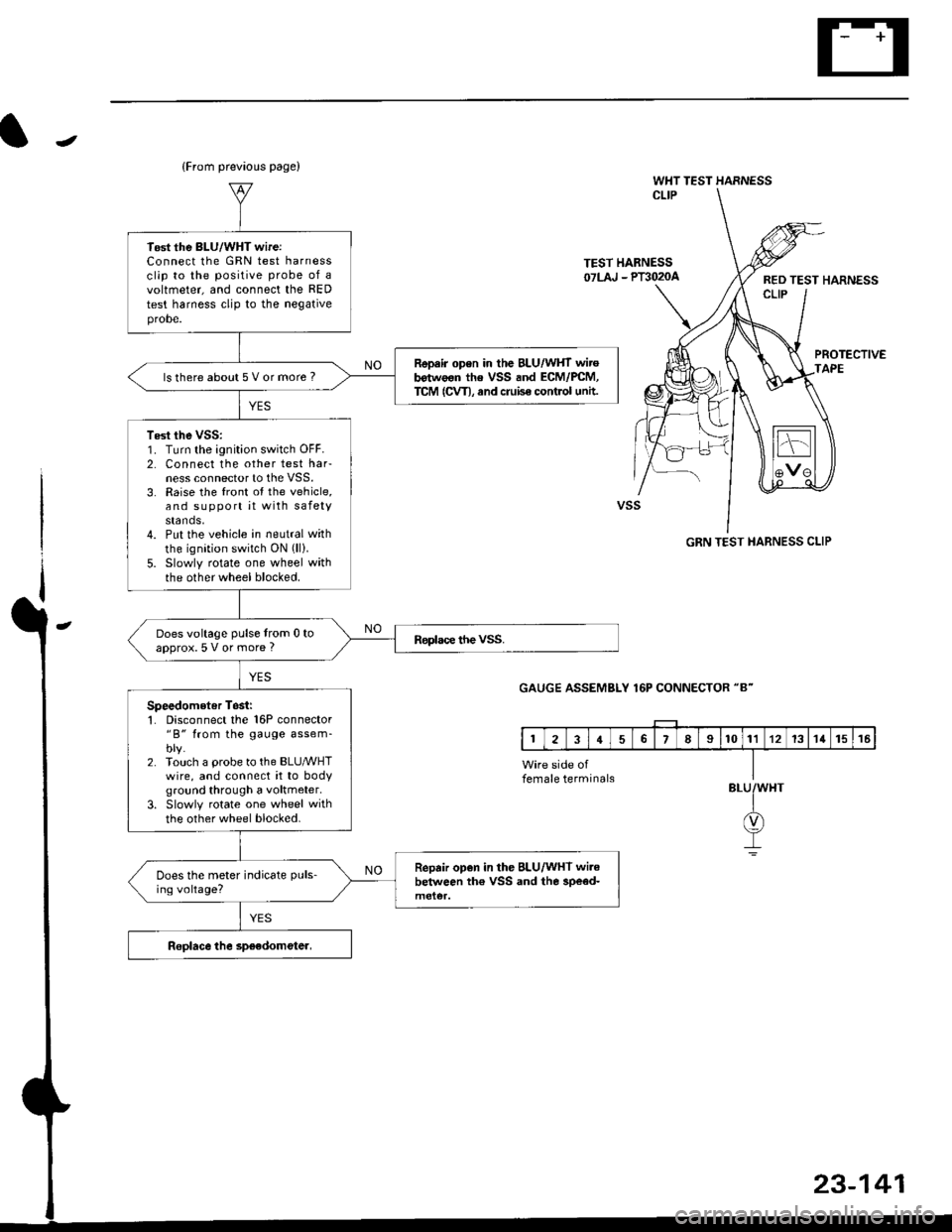
WHT TEST HARNESSCLIP
TEST HABNESS07LAJ - Plil020aRED TEST HARNESSCLIP
PROTECTIVEAPE
GRN TEST HARNESS CLIP
GAUGE ASSEMBLY 16P CONNECTOR "8"
BLU
23-141
Tost the BLU/WHT wireiConnect lhe GRN test harnessclip to the positive probe of avoltmeter, and connect the RED
test harness clip to the negativeprobe.
Repair open in the BLU/WHT wirob€twoon the VSS and ECM/PCM,TCM (CVT), and cruise control untt.ls there about 5 V or more ?
Test the vss:1. Turn the ignition switch OFF.2. Connect the other test harness connector to the VSS.3. Raise the front ot the vehicle,and support it with safetystands,4. Put the vehicle in neutral with
the ignition switch ON (ll).
5. Slowly rotate one wheel withthe other wheel blocked.
Does voltage pulse from 0 toapprox.5 V or more ?
Speedometer Tosii'1. Disconnect the 16P connector"B" from the gauge assem-blv.2. Touch a probe to the BLUMHTwire, and connect it to bodyground through a voltmeter.
3. Slowly rotate one wheel with
the other wheel blocked.
Repair open in the BLU/WHT wi.ebelween th€ VSS and the 3pe€d-Does the meter indicate puls-
ing voltage?
female terminals
Page 1723 of 2189
)1
ITRUNKLIGHT
GRNiRED LT GRN/ NED
AA
Ii,llh* T#,
I lctoseo : Door open ) | (ctoseo . ooo, open
I Looen Doot dosed J I Loner :ooot closet
tl
ll-: -l
@
wl
r,*1.,. ,,Tr,
,
I llltii irl:rx l5|i;e''lv
|
'r-1--
I
IBLU/YEL
TGFIVRED
I *r.oro,ro
I coNTRor uNrr
fF7IY \IT \
|L
GRN
AA
Y6su-' YFHrLo,,"
liili.}
',"**, r
liHi:
e*,**, r
ll-;
KEYLESS RECEIVER CIRCUIT(ln lhe audio unrl)
l"'l"l''o'*i*"
| |-"'i:"j^,"
l'*tectotroI coNTROL UNIT
I ,Y,
IBLU/RED
A
Y.r'ro,u
l:!llT -, ..".-
I
l-ope1 (ey temoved
BLK
I
);
G402
23-253
Page 1743 of 2189

Description
)
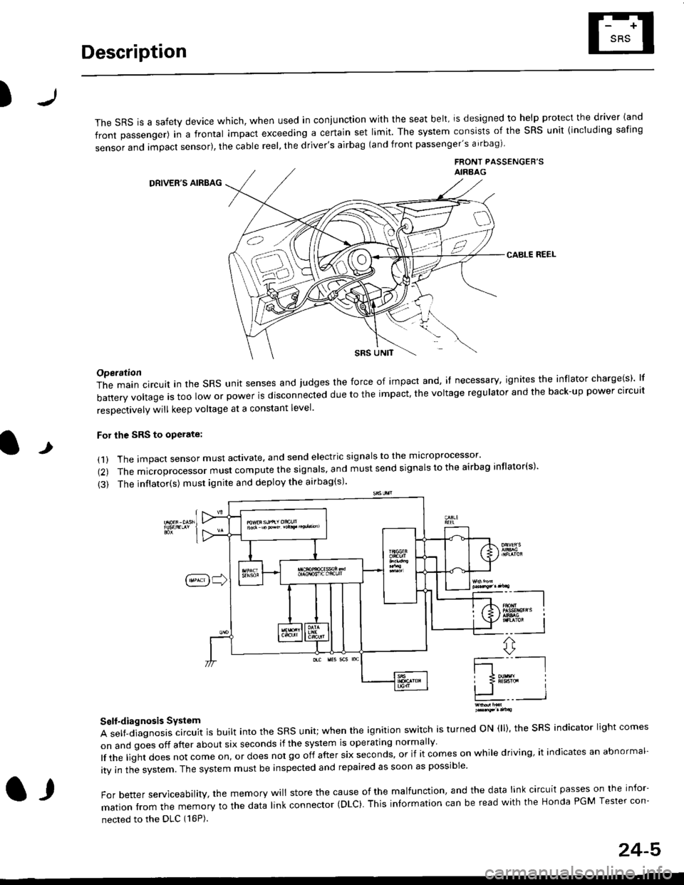
The sRS is a safety device which, when used in coniunction with the seat belt, is designed to help protect the driver land
front passenger) in a frontal impact exceeding a certain set limit. The system consists of the sRS unit {including safing
sensor and impact sensor), the cable reel, the driver's airbag (and front passenger's airbag)
FRONT PASSENGEB'SAIRAAG
DRIVER'S AIRBAG
CABLE REEL
SRS UNtT
t
Operation
The main circuit in the SRS unit senses and judges the force of impact and, if necessary, ignites the inflator charge(s) lf
battery voltage is too low or power is disconnected due to the impact, the voltage regulator and the back-up power clrcult
resoectivelv will keep voltage at a constant level.
For the SRS to operate:
(1) The impact sensor must activate. and send electric signals to the mlcroprocessor'
(2) The microprocessor must compute the signals' and must send signals to the airbag inflator(s)'
{3) The inflator(s) must ignite and deploy the airbag(s)'
_"-_-l
Ir3B!#h i
!.. I
ffi,*
Self-diagnosis System
A self-diagnosis circuit is built into the SRS unit; when the ignition switch is turned ON (ll), the SRS indicator light comes
on and goes off after about six seconds if the system is operating normally
lf the liglt does not come on, or does not go off after six seconds, or if it comes on while driving, it indicates an abnormal-
ity in the system. The system must be inspected and repaired as soon as possible
For better serviceability, the memory will store the cause of the malfunctlon, and the data link circuit passes on the infor-
mation from the memory to the data link connector (DLC). This intormation can be read with the Honda PGM Tesler con-
nected to the DLC (16P).
l,
24-5
Page 1747 of 2189

)
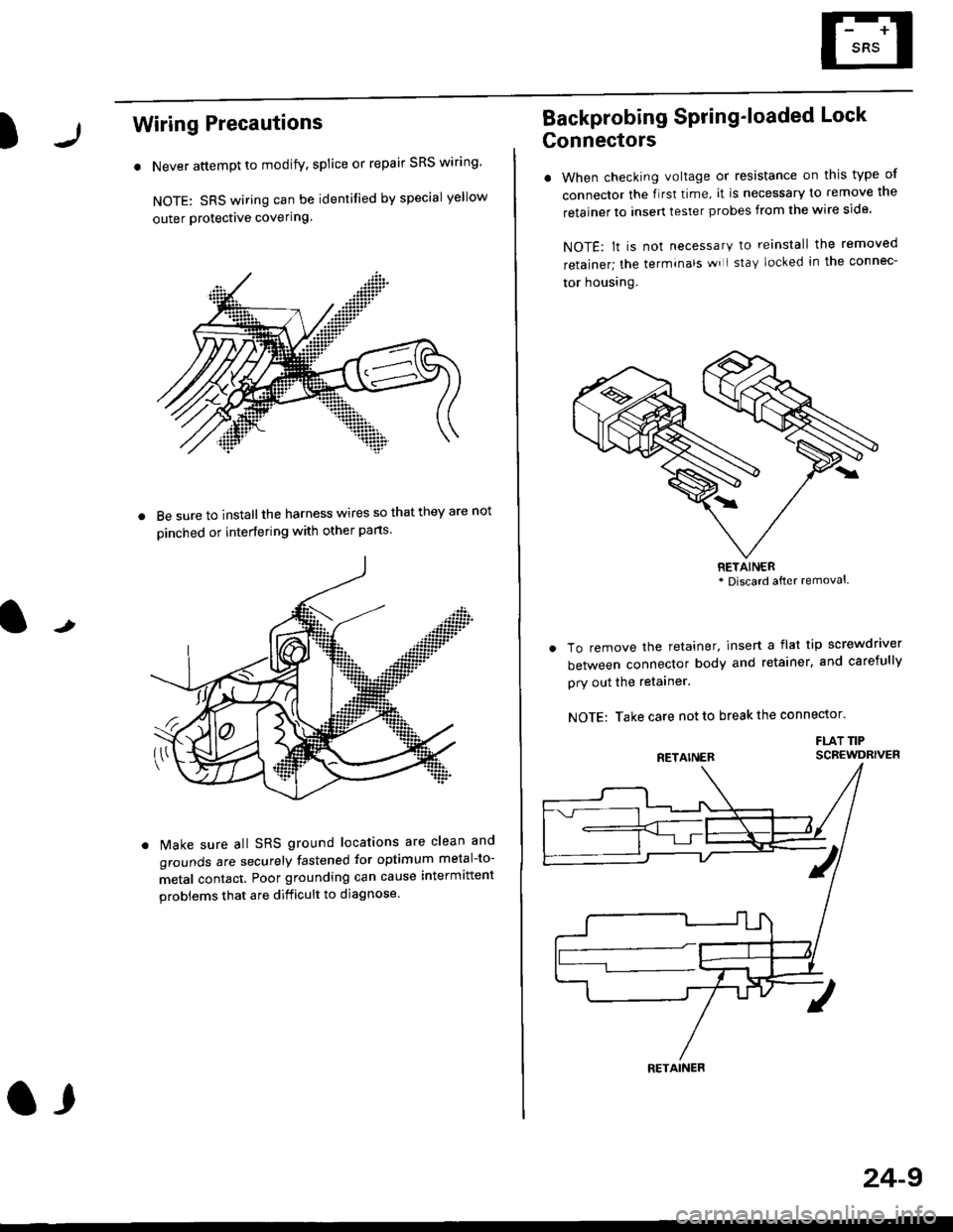
Wiring Precautions
. Never attempt to modify, splice or repair SRS wiring'
NOTE: SRS wiring can be identified by special yellow
outer Protective covering.
8e sure to install the harness wires so that they are not
oinched or interfering with other parts.
t
Make sure all SRS ground locations are clean and
grounds are securely fastened for optimum metal-to-
metal contact. Poor grounding can cause intermittent
problems that are difficult to diagnose.
a,
24-9
Backprobing Spring'loaded Lock
Gonnectors
. When checking voltage or resistance on this type of
connector the flrst time, it is necessary to remove lne
retainer to insert tester probes from the wire side.
NOTE: lt is not necessary to reinstall the removed
retainer; the terminals wi I stay locked in the connec-
tor housrng.
To remove the retainer, insert a flat tip screwdriver
between connector body and retainer, and carefully
pry out the retainer.
NOTE: Take care not to break the connector.
FLAT TIPSCBEWDRIVER
RETAINER* Discard after removal.
RETAINER