Page 943 of 2189

Electrical Troubleshooting ('99 - 00 Models)
Troubf eshooting Flowcharl - AIT Gear Position Switch {Short) {cont,d}
From page 14 265
LGl IBRN/BLK) LG2 {BRN/BLK}
Wire side of female terminals
A t32Pl jl B {25P)
ATP D (YEL)
LG1 {BRN/ALKILG2 IBRN/BLK)
Measure ATP NP Voltage:'1. Shift to all positions other thanEorI2. Measure the voltage betweenthe A9 and 820 or 922 te(mi-nals.
Check for short in the wirebetwoen ths Ag terminal and theA/T gerr position switch, .nd inthe E .nd E position 3ignalwiros botween the A/T gearposition indic.tor and the A/Tgear positaon switch. lf wircs .reOK, check tor loose terminal tit inthe PCM connectols. lf n€ces-3ary, substitute a known-goodPCM and rocheck.
ls there approx. 10 V?
Me.sure ATP D Vohago:1. Shift to all positions otherthan E.2. Measure the voltage betweenthe 47 and 820 ot 822 tet-r'i-nals,
Check tor 3hort in lhe wireb€twaen thc A7 terminel and theA/T g6ar position switch. lf wir.sare OK, ch.rck to. loose terminalfit in th6 PCM connectoF. lf nsc-ossary. substhute a known-goodPCM and ..check.
ls there approx. 10 V?
a l32Pl ll B (25P1
To page 14-267
14-266
Page 944 of 2189

M6asure ATP S Voliag€:1. Shift to all positions other
than E.2. Measure the voltage between
the D13 and 820 or 822 termi
nals.
Check for short in the wire
between the D13 terminal and
the A/T gear position lwitch orA/T goar position indicator. Itwir6s are OK, check lor loose l€r-
minal fit in the PCM connectors.ll nec*3arv, substitute a known'good PCM and r6check.
ls there approx. '10 V?
Measure ATP L Voltage:1. Shi{t to all positions other
than E.2. Measure the voltage between
the A22 and 820 or 822 termi-nals.
Check lor sho.t in ihe wire
betwgon the A22 terminal and
th. A/T geat position switch or
A/T gear position indicator. It
wires are OK, ch€ck for 10036 ter-minal fit in the PCM connectors.lf n6cessery, substitute a known_good PCM and recheck.
ls there approx- 10 V?
Check tor loos€ terminalfit in the
PCM connectors, It nec6s3arY,
substitute a known-good PCM
and rech6ck.
From page 14-266
B t2sP)
LG1{BRN/BLKI
t32Pl
PCM CONNECTORS
Wire side of Iemale terminals
PCM CONNECTORS
D (16P1
ATP S {LT GRN/RED)
LG2 (BRN/BLKI
B t25Pl
Page 945 of 2189

Electrical Troubleshooting {'99 - 00 Models)
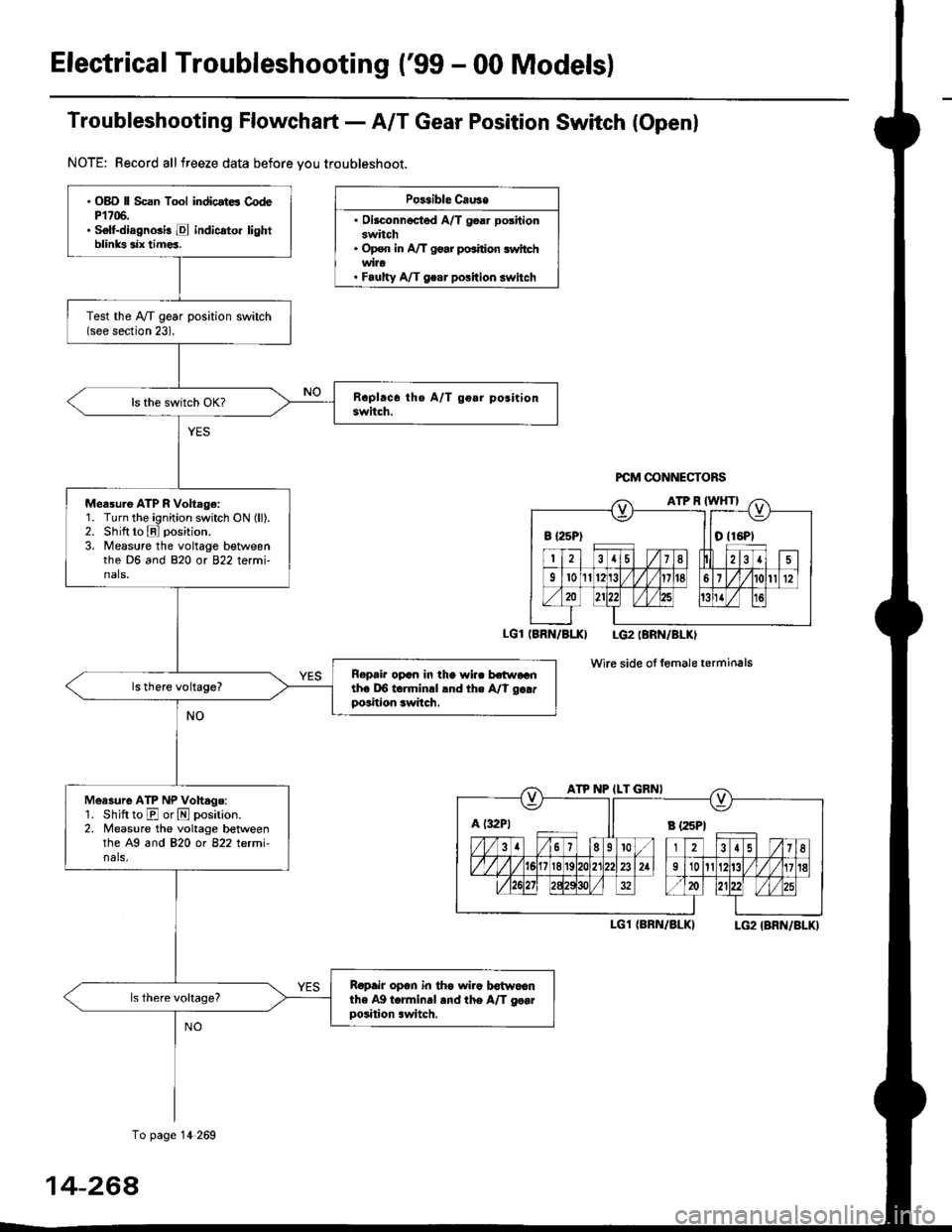
Troubfeshooting Flowchaft- AIT Gear Position Switch (Openl
NOTE: Record allfreeze data before vou troubleshoot.
Po$ible Cau3e
. Oilconnected A/T goar positionswitch. Op€n in A/T go.r po.ition switchwi?o. Faulty A/T gear polition switch
PCM @NNECTORS
(BRN/BI.XI LG2IBRN/BLKI
wire side of fomale terminals
I-G1 (BRN/BLKILG2 {BRN/BLK)
B {25P) I tO (16P1
ATP NP ILT GRNI
A t:r2Pt Il s tzspt
. OBD ll Scan Tool indicstE CodeP1706.. Selt-diagnGi! E indicato. lightblinks six tim€a.
Test the IVT gear position switch(see section 23).
Measu.e ATP R Voltage:1. Turn the ignition switch ON (ll).2. Shift to E position.
3. Measure the voltage betweenthe D6 and 820 or 822 termi-nals,
Ropair opcn in the wi.. hr.raGnth6 DO torminrl lnd the A/t g..rposition awitch.
Measure ATP NP Vohage:'1. Shift to E or N position.2. Measure the voltage betweenthe A9 and 820 ot 822 letmi-nals,
Ropair op6n in th€ wiro b€{woanthe Ag t.rminal and the A/T go..position .witch.
To page 14 269
14-264
Page 946 of 2189
From page 14-268
LGl IBRN/BLK}
Moasule ATP D voltago:1. Shift to El position.
2. Measure the voltage between
the A7 and 820 or 822 termi
nals.
Repair open in the wira betwo6nthe A7 torminal and the A/T ge.rpo3ition switch.
Measure ATP S Vollag6:'1. Shiftto E position.
2. Measure the voltage betweenthe D13 and 820 or B22 terminals.
Repair op€n in tho wire betweenihe D13 terminal .nd the A/Tgear position switch,
A {32P} ll B l25Pl
LGl IBRN/BLK) LG2 (BRN/BLKI
(cont'd)
14-269
To page 14-270
Page 947 of 2189
Electrical Troubleshooting {'99 - 00 Models}
Troubleshooting Flowchart - A/T Gear Position Switch (Openl (cont'dl
Bepair opon in the wiro bgtw€enlho A22 torminal and the A/Tgoar poihion lwitch.
PCM CONNECTORS
B (25P1
LGT (BFN/ALK}
PCM CONNECTOR B I25PI
12.15 / 7I
9't0l1Br1/l/41it8
ll lLG2
o) (o)
IBRN/BLKI
Wire side of female terminals
From page 14-8-269
Msasuro ATP L Voftage:1. Shiftto E position.
2. Measure the voltage betweenthe A22 and 820 or 822 termi-nals,
Check LG Wiro for .n Open Cir-cuit:']� Turn the ignition switch OFF.2. Check lor continuity betweenthe 820 t€rminal and bodyground, and between the 822terminal and body ground.
Ropai' op.n in the wir€a botw.€nthe 820 rnd 822 toJminals .ndbody ground, and .opsi. poolground (Gl01l.
Check tor loose te.minal frt in th6PCM conn€ctors, lf n€cessary, sub-stitut€ a knowo-good PCM anda6check,
Wire side of female terminals
14-270
Page 948 of 2189

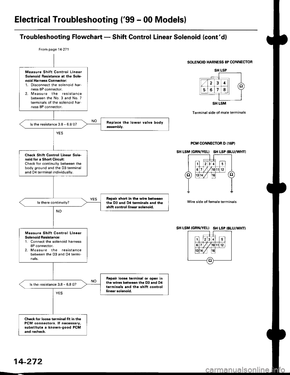
JTroubleshooting Flowchart - Shift Control Linear Solenoid
NOTE: Record all freeze data before you troubleshoot
Possiblc Cause
. Disconn€cted solenoid harnos3
connectol. Short or oDen in shilt controllinetr solonoid wiro. Faulty shift control linear sole_
noid. Op€n in VB SOL wite. ODen in PG'l and PG2 wires or
poor ground {G10'l)
f,
wire side ot female terminals
LG1 IBRN/BLKILG2IBRN/BLK)
{cont'd)
14-271
PCM CONNECTORS
B(25P) - Dll6P)
.OBD ll Scan Tool indicatos
Code P1870.. Solf-diagnosis E indic.lor light
indic.t€s Code 30.
M6a3ure VB SOL voltage:1. Turn the ignition switch OFF.
2. Disconnect the B 125P) and D(16P) connectors from the
PCM,3. Turn the ignition switch ON (ll).
4. Measure the voltage between
the D5 and 820 or 822 terminals.
Repair open or shod in the wire
between the D5 terminal and the
under-dash tuso/telay box.
Check the Ground Circuitl1. Turn the ignition switch OFF.2. Check lor continuity between
the terminafs 82 and 822 and
between terminals 810 and
820.
Repair open in the wi.e betwoen
the termin.ls 82, B10, B20, and
822 and G101. Repair Poolground (G101).
LG1 IBRN/BLKI
PCM CONNECTOR B PsPI
PG,I IBLK)
10 page 14-272
a
Page 949 of 2189

ElectricalTroubleshooting ('99 - 00 Models)
Troubleshooting Flowchart - Shift Gontrol Linear Solenoid (cont'dl
SOI."ENOID HARNESS 8P CONNECTOR
Terminal side of male terminals
PCM CONNECTOR D {16P}
SH LSM IGRN/YELI SH LSP {BLU/WHTI
Wire side oI temale terminals
SH LSM {GRN/YELI SH LSP IALU/WHT}
tuom page 14 271
Measure Shift Control LinearSolenoid R6sistance at the Sole-noid Hrrness Connector:1. Disconnect the solenoid harness 8P connector.2. Measure the resistancebetween the No. 3 and No- 7terminals oI the solenoid harness 8P connector,
ls the resistance 3.8 - 6.8 o?
Check Shift Control Lin€ar Sole-noid tor a Short Circuit:Check for continuity between thebody ground and the D3 terminaland D4 terminal individually.
Rep.ir short in th€ wir€ tr€twlrenihe D3 and D4 torminab .nd theshift cont.ol line.. solenoid.
Measure Shitt Conirol LineerSolenoid Resbtance:1. Connect the solenoid harness8P connector.2. Measure the resistancebetween the D3 and D4 termi-nats.
Repeir loose ierminrl or open inthe wire3 between tho D3 and D4terminals end the shift controllinear solenoid.
ls the resistance 3.8 - 6.8 O?
Check tor loose terminal fit in thePCM connector3, It necessary,substitute a known-good PCMand recheck.
SH LSP
SH LSM
14-272
Page 962 of 2189
Troubleshooting Flowchart - Shift Control System
NOTE: Record allfreeze data before you troubleshoot
Possible cause
Faultv shift control svstem' OBD ll Scan Tool indicates Codo
P1Ato.. Self-diagnosis E indicator light
indicatos Code 42.
Check for Anoth€r Code:Check whether the E indicator
light indicates another code.
P€rform the Tloubleshooting
Flowchart for the indicated
Code(sl.
ls the E indicator light indi
cate another code?
Check Stall Speed RPM:
Measure the stall sPeed RPM(see page 14-298).
ls the stall speed over 3,500 rpm?
ls the stall speed below 2,000 rpm?
Test-drive and Check Engine
Speed:L Drive the vehicle at 30 mph
150 km/h) constantly for sev-
eral mlnutes.2. Check the engine speed
ls the engine speed within the
specification (see Page 14'296
and 14'297)?
14-245