Page 273 of 2189
Component Locations
Index (cont'd)
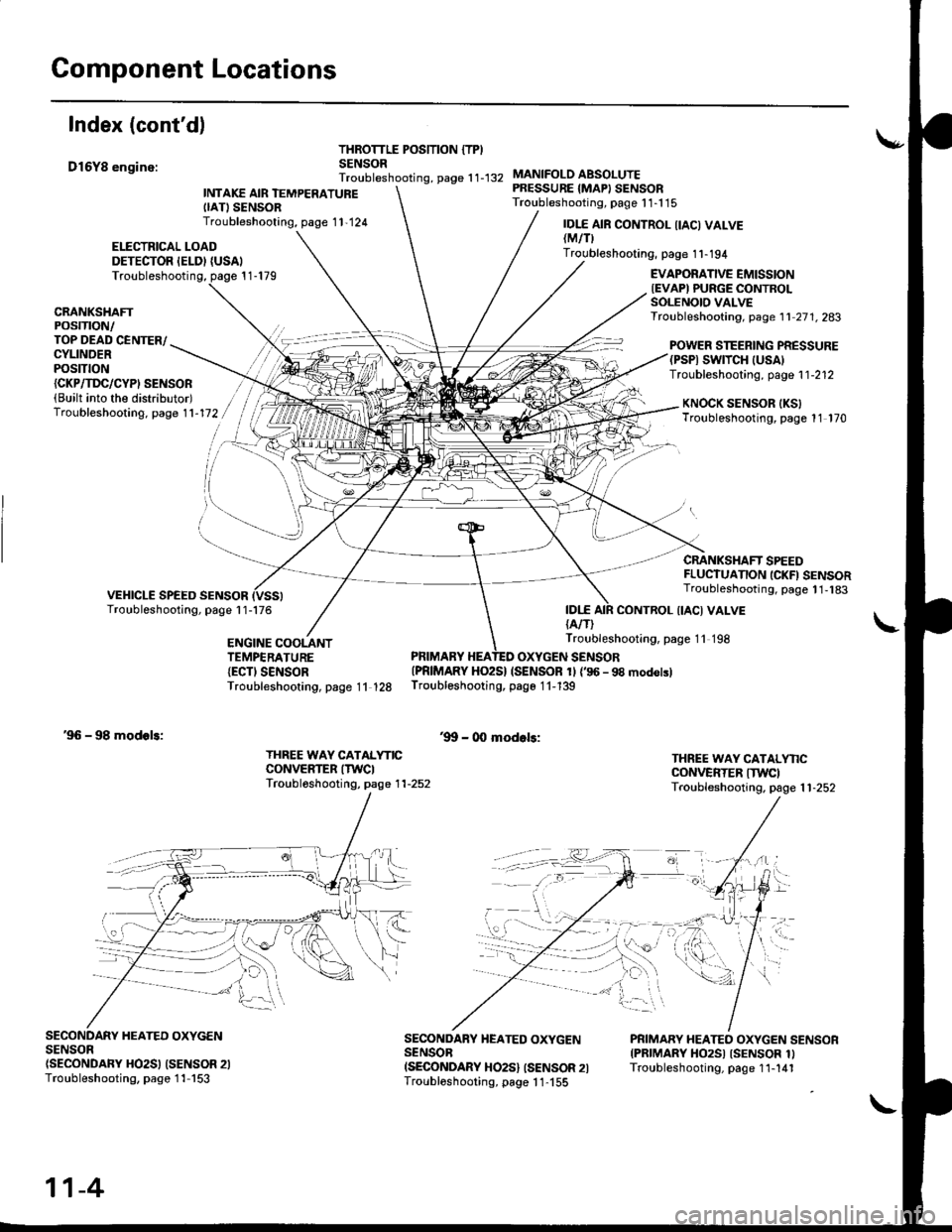
D16Y8 enginc:
THROTTLE POSITION {TPISENSORTroubleshooting, page 1 1-132
ELECTRICAL LOADDETECTOR IELDI {USAI
INTAKE AIR TEMPERATUREIIATISENSORTroubleshooting, page 1 1,124
MANIFOLO ABSOLUTEPRESSURE {MAPI SENSORTroubleshooting, page 1 1-1 15
IDI.E{A/T)
IDI.E AIR CONTROL IIACI VALVElMtflTroubleshooting, page 1 1-194
Troubleshooting, page 1 1-179EVAPORATIVE EMISSIONIEVAPI PURGE CONTROLSOLENOIO VALVETroubleshooting, page 1 1 27 1. 283CRANKSHAFTPOSTTTON/TOP DEAD CENTER/CYLINDERPOStTtON
POWER STEERING PRESSURE(PSPI SWTTCH |USA)Troubleshooting, page 1 1-212{CKP/TI'C/CYPI SENSOR(Built into the distributor)Troubleshooting. page 1 1-172KNOCK SENSOR IKSITroubleshooting, page 11 170
CRANKSHAFT SPEEDFLUCTUANON ICKFI SENSORTroubleshooting, page 1 1,183
CONTROL {IACI VALVE
ENGINE COOLANTTEMPERATURE{ECTI SENSORTroubleshooting, page 11 128
Troubleshooting, page 11 198
PRIMARY HEATED OXYGEN SENSOR{PRIMARY HO2S} (SENSOR 1l {'96 - 98 modolslTroubleshooting, page 1 1-139
'9!t - 00 modols:'96 - 98 modols:
THREE WAY CATALYNCCONVERTER ITWCITroubl6shooting, page 1 1-252
THREE WAY CATALYNCCONVERTER ITWCITroubleshooting. page 1 1-252
SECONDARY HEATED OXYGENSENSOn(SECONDARY HO2SI (SENSOR 2ITroubleshooting, page 1 1-153
SECONDARY HEATED OXYGENSENSOBISECONDARY HO2S} ISENSOR 2ITroubloshooting, page 1 1-155
PRIMARY HEATEO OXYGEN SENSORIPRIMARY HO2SI ISENSOR 1ITroubleshooting, page 1 1-141
11-4
Page 274 of 2189
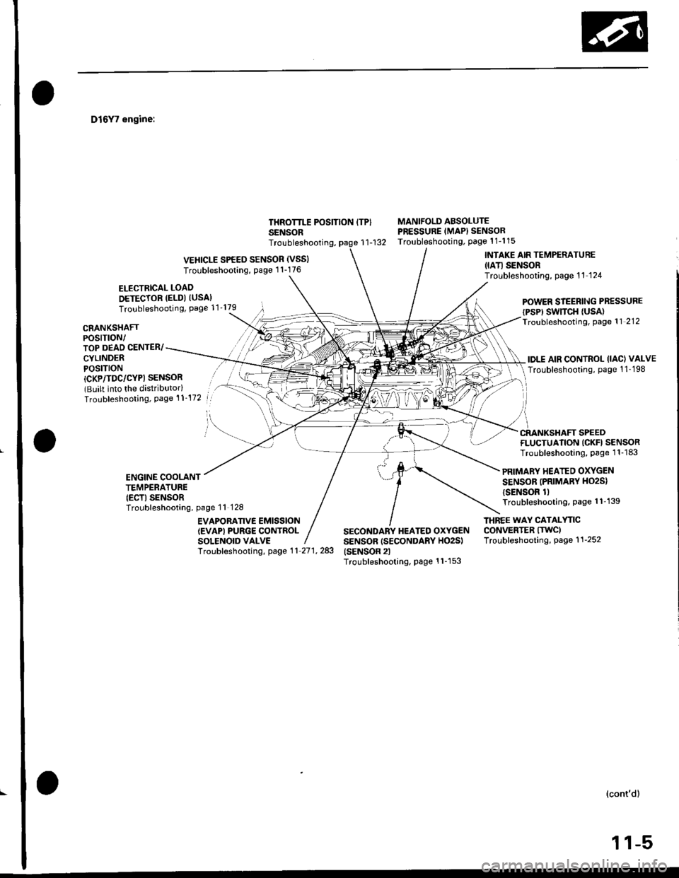
D16Y7 engine:
ELECTRICAL LOAO
DETECTOR (ELD) IUSA}Troubleshooting, Page 11'179
THROTTLE POSITION ITPISENSOR
MANIFOLD ABSOLUTEPRESSURE (MAPI SENSORTroubleshooting, Page 1 1-1 15r1-132
CRANKSHAFTPOSTTTON/TOP DEAD CENTER/
CYLINDERPOSITION
POWER STEERll\lG PRESSURE
{PSP' SWTTCH {USA)Troubleshooting, Page 11 212
IDLE AIR CONTROL (IAC) VALVE
Troubleshooting, page 1 1-198
Troubleshooting,
VEHICLE SPEED SENSOR (VSSI
Troubleshooting, Page 1 1-176
INTAKE AIR TEMPERATURE
IIATI SENSORTroubleshooting, page 11 124
l
/i
CRANKSHAFT SPEED
{CKP/TDC/CYPI SENSOR(Built into the distributorlTroubleshooting, Page 't 1-172
FLUCTUATION ICKFI SENSORTroubleshooting, Page 1 1-183
PRIMARY HEATED OXYGEN
SENSOR (PRIMARV HO2S)
{SENSOR 1lTroubleshooting, page 1 1'139
ENGINE COOLANTTEMPERATURE(ECTI SENSORTroubleshooting, page 11 128
EVAPOBATIVE EMISSION(EVAPI PURGE CONTROLSOLENOID VALVE
THNEE WAY CATALYTICCONVERTER ITWCITroubleshooting, page 1 1-252
Troubf eshooting, page 1 1 27 1, 283
SECONDARY HEATED OXYGENSENSOR (SECONDARY HO2S)(SENSOR 2lTroubleshooting, Page 1 1-1 53
(cont'd)
,l .ltr| | -r,
Page 275 of 2189
Component Locations
Index (cont'dl
Bl6A2 engine:
INTAKE AIR TEMPERATURE{IAT} SENSORTroubleshooting, page 1'1-125
MANIFOLO AESOLUTEPRESSURE IMAPI SENSORTroubleshooting. page 11-1 19IOLE AIR CONTROL {IAC) VALVETroubleshooting, page 1 1,196
ELECTRICAL LOADDETECTOR IELDI (USA)
Troubleshooting, page 1 1-180
THROTTLE POSITION ITPISENSORTroubleshooting, page 11-134
CRANKSHAfiPOStTtON/TOP DEAD CENTER/CYLINDERPOStTtON{CKP/TDC/CYPI SENSOR(Bualt into the distributor)Troubleshooting,page 11-174
POWER STEERING PRESSURE{PSPI SWTTCH (USA)
Troubleshooting, page 1 1-214
VEHICLE SPEED SENSOR {VSS}Troubleshooting, page 1 1-177
ENGINE
CRANKSHAFT SPEEDFLUCTUATION (CKFI SENSORTroubleshooting, page 11- t85TEMPERATUREIECTI SENSORTroubleshooting, page I 1-128
THREE WAY CATALYTICCONVERTER ITWC)Troubleshooting, page 1 1,252
S€CONOARY HEATED OXYGENsf rlsoR
sfCoNDARY HO2SI {SENSOR 2): ?shootrng, page 11 155
-6
PRIMARY HEATED OXYGEN SENSORIPRIMARY HO2S) ISENSOR 1ITroubleshooting, page 1 1-141
11
Page 276 of 2189
I
CLUTCH SWITCH lDl6Y5 onginoM,/TITroubleshooting, page 1 1-218
'96 - 98 modsls:
Sell-diagnostic Procedures.page 11 81
ENGINC CONTROL MOOUI.T(FCMI/POWERTRATN
CONTROL MODULE IPCMITroubleshooting, page 1 1-107
'9!, - 0o modol3:
PGM.FI MAIN RELAYRslay Testing, page 11-237Troubleshooting, page 1 1-238PGM.FI MAIN RELAYRelay Testing, page l1 237Troubleshooting, pago 1'! 238
SERVICEl2Pl
CONNECTOR
ENGINE CONTROL MODU1T(ECM}/POWERTRAIN
CONTROL MODULE IPCMITroubleshooting, page 11 111SERVICE CHECK CONNECTORtzPlSelf-diagnostic Procedures,page 11-81
Self-diagnostic Procedures,page 11-81
{cont'd)
11-7
Page 277 of 2189
Component Locations
Index (cont'dl
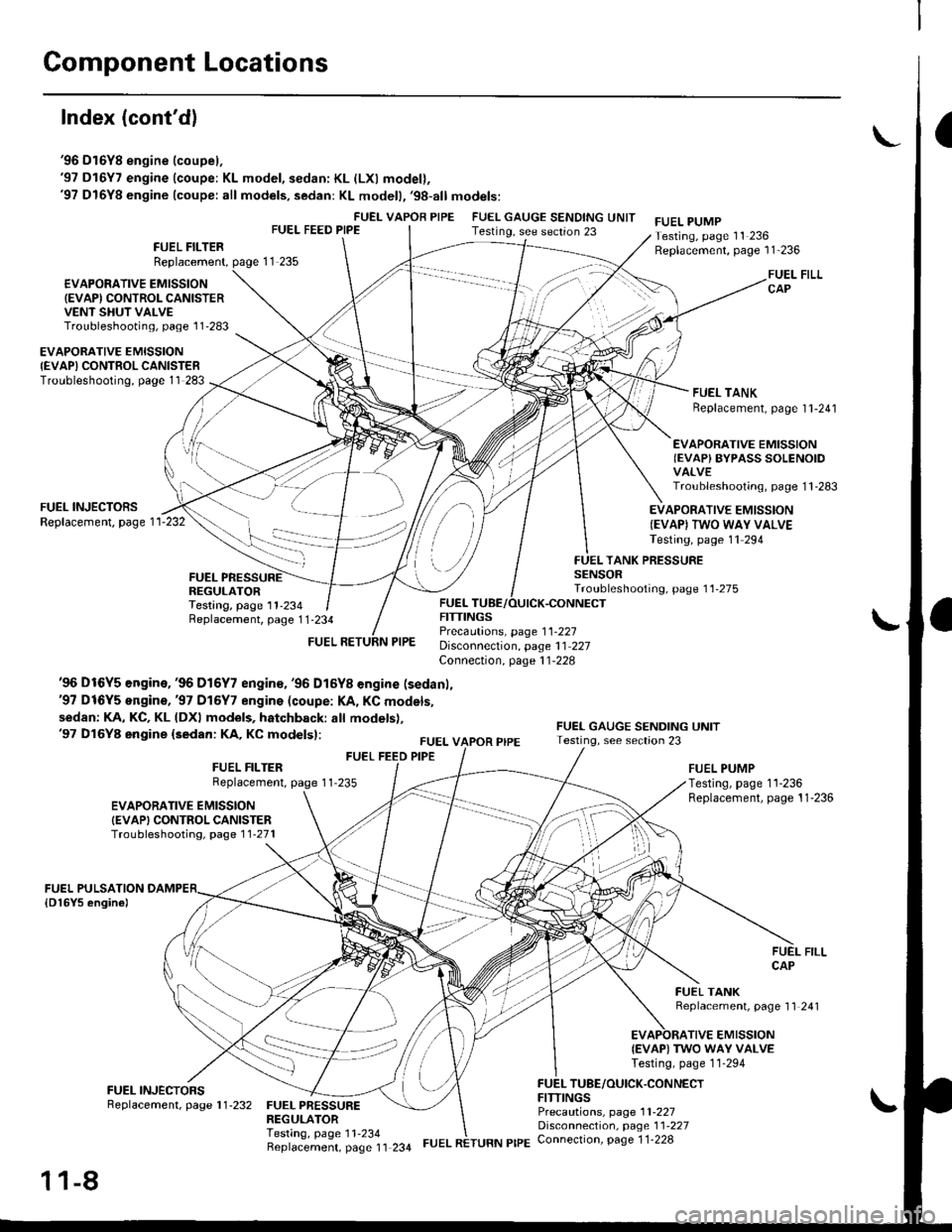
'96 D16Y8 engine (coupel,'97 D16Y7 engine (coupe: KL model, sedan: KL (LXl model),'97 D16Y8 engine (coupe: all models, sedan: KL modell,'98-all models:
FUEI- VAPOR PIPEFUEL FEED PIPEFUEL GAUGE SENDING UNITTesting, see section 23FUEL PUMPTesting, page 11 236Replacement, page 11 236FUEL FILTERReplacement,
€VAPOFATIVE EMISSION(EVAPI CONTROL CANISTERVENT SHUT VALVETroubleshooting, page l1'283
FUEL FILLCAP
FUEL TANKReplacement, page I l-241
EVAPORATIVE EMISSIONIEVAPI CONTROLCANISTERTroubleshooting, page 11 283
EVAPORATIVE EMISSIONIEVAP) BYPASS SOLENOIDVALVETroubleshooting, page 1 1 -283
FUEL INJECTORSReplacement, page 1 1-232EVAPORATIVE EMISSION(EVAPI TWO WAY VALVETesting, page 11 294
FUELREGULATORTesting, page 11-234
TANK PRESSURESENSORTroubleshooting, page 11-275
Replacement, page 1 1-234
'96 Dt6Y5 engine,'96 D16Y7 engin€, '96 D16Y8 engine (sedanl,'97 D16Y5 engine,'97 Dl6Y7 engins (coupe: l(A, KC models,
sedan: KA, KC, KL (DXl models, hatchback: all models),'97 Dl6Y8 engine (sedan: KA, KC modelsl:
FUEL FEED PIPE
FUELFITTINGSPrecautions, page 1 1-227Disconnection, page 11 227Connection, page 11-228
FUEL VAPOR PIPE
FITTINGS
EVAPORATIVE EMISSIONIEVAPI CONTROL CANISTERTroubleshootiog, page 1 1-271
FUEL FILTERReplacement, page 1 1-235FUEL PUMPTesting, page 11-236Replacement, page 11-236
FUEL TANKBeplacement, page 11 241
TIVE EMISSION{EVAP) TWO WAY VALVETesting, page 11-294
TUBE/OUICK.CONNECT
FUEL PRESSUREREGULATORTesting, page 11'234Beplacement, page 11 234
Precautions, page 1 1-227Disconnection, page 11'227Connection, page 1 1-228
11-8
FUEL RETURN PIPE
Page 278 of 2189

'99 - 00 models:
EVAPORATIVE EMISSIONIEVAP} PURGE CONTROLSOLENOID VALVETroubleshooting, page 1 1'288FUEL GAUGE SENDING UNITTesting, see section 23
FUEL VAPOR PIPE
ONBOARD REFUELING VAPORR€COVERY IORVRIVENT SHUT VALVETest, page 11 296
EVAPORATIVE EMISSION
{EVAP) CONTROL CANISTERVENT SHUT VALVETroubleshooting, Page 1 1_288
EVAPORATIVE EMISSION
FUEL FILTERBeplacement, page 11-235
FUEL FEED PIPE
FUEL RETURN PIPE
FUEI- PUMPTesting, page 11 236Replacement, page 11-236
FUEL FILLCAP
{EVAPI CONTROLTroubleshooting, page 1 1_288
FUELPULSATION DAMPEB
FUEL INJECTORSReplacement, page 1 1'232
FUEL PRESSUREREGULATOR
EVAPORATIVE EMISSION
{EVAP) BYPASS SOLENOIDVALVETroubleshooting, page 1 1-288
FUELRAIL
FUEL TANK PRESSURESENSOBTroubleshooting, Page 1 1'274
EVAPORATIVE EMISSIONIEVAPI TWO WAY VALVETesting, page 11 295
Testing, page 11-234Replacement, page 11 234FUEL TUBE/OUICK.CONNECTFITTINGSPrecautions, page 1 l-227Disconnection, page 11 227Connection, page 1 1-228
Replacement, page 1 1-241
I(cont'd)
1 1-9
Page 350 of 2189
Troubleshooting
Troubleshooting Procedures
How To Begin Troubleshooting
When the Malfunction Indicator Lamp (MlL) has been reported on, or there is a driveability problem, use the appropr'-
ate orocedure below to diagnose and repair the problem'
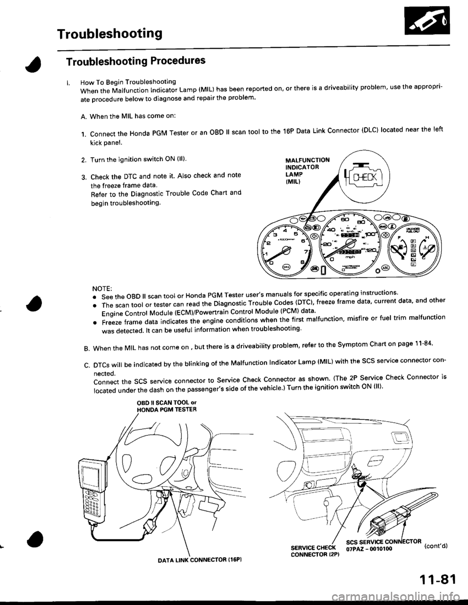
A. When the MIL has come on:
,1. connect the Honda PGM Tester or an oBD ll scan tool to the 16P Data Link connector (DLC) located near the left
kick panel.
2. Turn the ignition switch ON (ll)
3. Check the DTC and note it. Also check and note
the freeze trame data
Refer to the Diagnostic Trouble Code Chart and
begin troubleshooting.
NOTE:
.SeetheoBD||scantoolorHondaPGMTesteruser,smanua|sforspecificoperatinginstructions..
.Thescantoo|oltestercanreadtheDiagnosticTroub|ecodes(DTc},freezeframedata,currentdata,andother
Engine Control Module (ECM)/Powertrain Control Module (PCM) data'
oFreezeframedataindicatestheengineconditionswhenthefirstma|function,misfireorfue|trimma|function
was detected. lt can be useful information when troubleshooting'
B. When the MIL has not come on , out there is a d riveability problem, refer to the Symptom Chart on page 1 1-84'
c.DTcswi|lbeindicatedbytheb|inkingoftheMa|function|ndicatorLamp(M|L)withthescsserviceconnectorcon.
nected.
Connect the SCS service connector to Service Check Connector as shown (The 2P Service Check Connector is
|ocatedunderthedashonthepassenger,ssideofthevehic|e')TurntheignitionswitchoN{||)'
OBO ll SCAN TOOL olHONOA PGM TESTER
SERVICE CHECKCONNECTOR I2P)
scs sERvlcE(cont'd)
MALFUNCTIONINDICATORLAMP
DATA LINK CONNECTOR Il6PI
07PAZ - (x)l0100
11-81
Page 351 of 2189
Troubleshooting
Troubleshooting Procedures (cont,dl
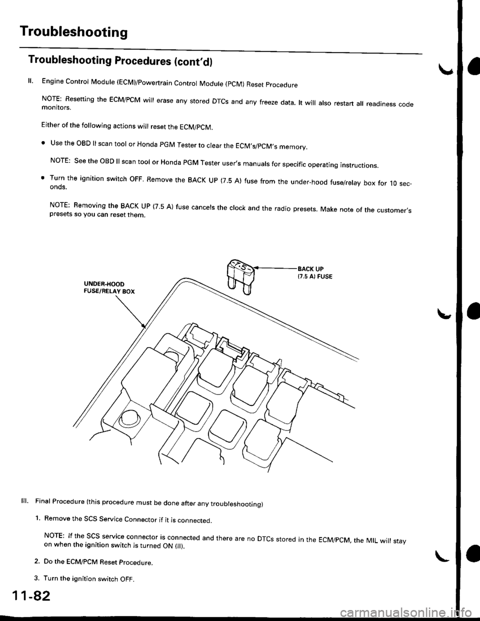
ll, Engine Control Module (ECM)/powertrain Control Module (pCM) Reset procedure
NoTE: Resetting the EcM/PcM will erase any stored DTcs and any freeze data. lt will also restart all readiness codemonitors.
Either of the following actions will reset the ECM/PCM.
. Use the OBD ll scan tool or Honda pGM Tester to clear the EClM,s/pCM,s memory.
NorE: see the oBD ll scan tool or Honda PGM Tester user's manuals for specific operating instructions.
' Turn the ignition switch oFF. Remove the BACK uP (7.5 A) fuse from the under-hood fuse/relay box for 10 sec-onds.
NorE: Bemoving the BACK uP (7 5 A) fuse cancels the clock and the radio presets. Make note of the customer,spresets so you can reset then
lll. Final Procedure (this procedure must be done after any troubleshoottng)
1. Remove the SCS Service Connector if it is connected.
NoTE: If the Scs service connector is connected and there are no DTcs stored in the EcMipcM, the MtL will stayon when the ignition switch is turned ON 0l).
2. Do the ECM/PCM Reset procedure.
3. Turn the ignition switch OFF.
1-82