1999 HONDA CIVIC TMA
[x] Cancel search: TMAPage 359 of 2189
Troubleshooting
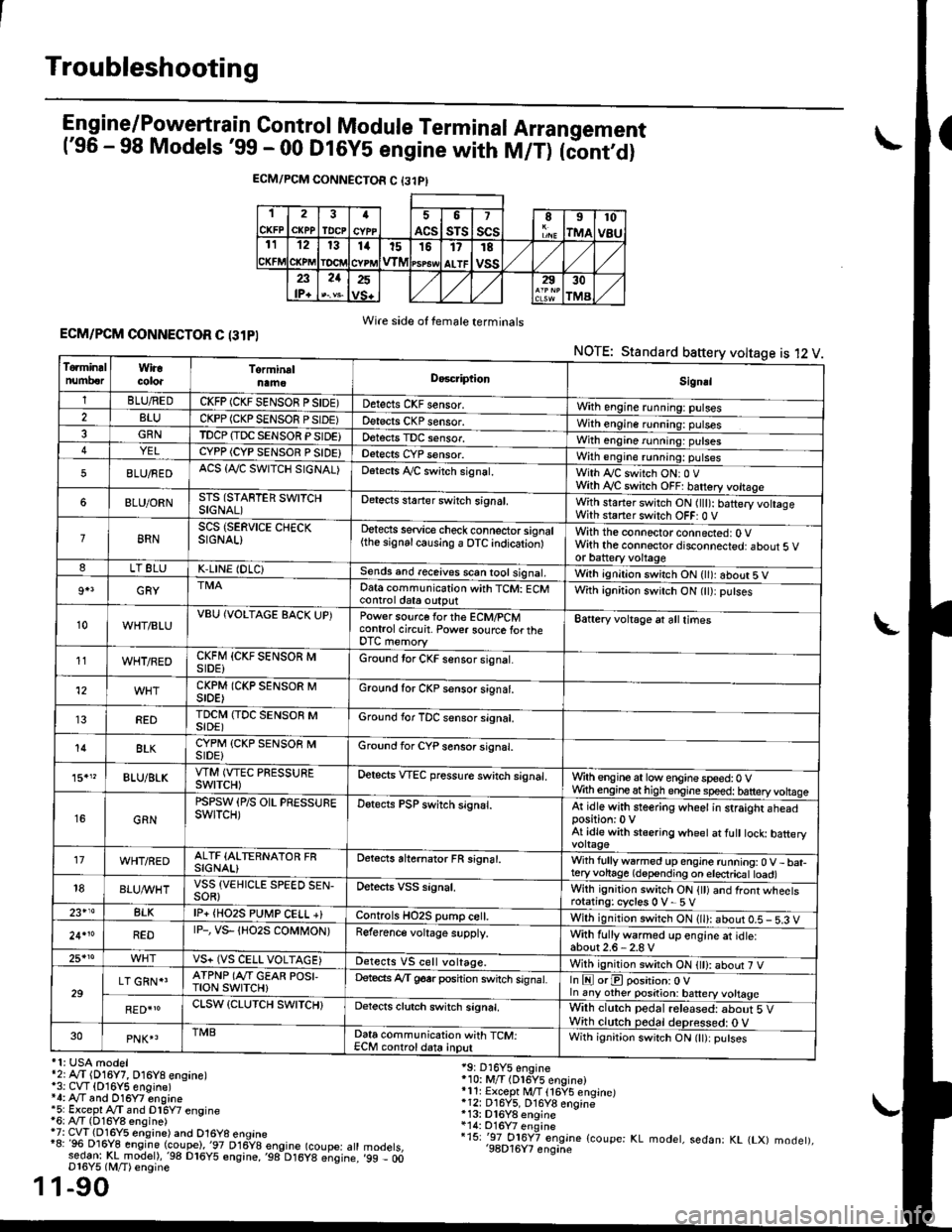
Engine/P_o_wgrtrain Control Module Terminal Arrangement('96 - 98 Models '99 - 00 Dt6y5 engine with M/T) tc'oniOi
ECM/PCM CONNECTOR C {31PI
1
CKFP
2
CXPPTDCPa
ACS
5
sTs
7
scsII
rMA
10
v8u121314t51517
ALTF
TE
vss23lP+
21252930
TMA
Wire side of female terminalsECM/PCM CONNECTOR C (31PI
NOTE: Standard baftery voltage is 12 V
'1: USA modelr2rA,.T (D16Y7, O16Y8 ensane)*3: CVT (O16Y5 engine)*4: Ay'T and O16Y7 engine'5: Excepl A./T snd Dl6Y7 engine16: Ay'T (D16Y8 ensine){7: CVT (Dl6Y5 eosine) and O16Y8 enoine"8: 96 Dl6Y8 engine (coupe),'97 D16y8 engine (coupe: atl:ed-9I t!!rnodelr,'98 D16y5 ensine,,98 D16y8 e;sine.D16Y5 lM/T) ensine
1-90
19: D16Y5 engine'10: M/T (Dl6Y5 engine)*11r Except M/T 116Y5 engine)*12: D16Y5, D16Y8 engine*13: Dl6Y8 enqine*14: O16Y7 enginei15: '-97 O16Y7 engjne (coupe: KL modet, sedan: KL (LX) modet),'98D16Y7 enqine'99 - 00
1
To.min!lnumberWiracoloaTorminalnameDo6criptlonSignal
1BLU/REDCKFP (CKF SENSOR P SIDE)Detects CKF sensor.With engine running: pulses2BLUCKPP (CKP SENSOF PSIDE)Detects CKP sensor.With engine running: pulses3GRNTDCP {TDC SENSOR PSIDE}Detects TDC sensor,With engine running: putses4YELCYPP (CYP SENSOR P SIDE)Detects CYP sensor.With engine running: pulses
5BLU/FEDACS {Tr'C SWITCH SIGNAL)Detects ,ay'C sw;tch signat.With Iy'C switch ONr 0 VWith Ay'C switch OFF: batrery vottage
6BLU/ORNSTS (STARTER SWITCHSIGNAL)Detects staner swilch signal,With staner switch ON ltlt): batery vohageWith staner switch OFF: 0 V
8RNSCS (SERVICE CHECKSIGNAL)Detects service check connector signal{the signalcausing a OTC indicationlWith the connector connected: O Vwith the connector disconnected: about 5 vor battery voltageLT 8LUK,LINE (DLC)Sends and receives scan iool signal,Wirh ignition switch ON { ): about 5 V
9+3GRYDat6 communication with TCM: ECMcontrol ctat6 outputWith ignition switch ON (tt):putses
10WHT/BLUVBU (VOLTAGE BACK UP)Power source forthe ECM/PCMcontrol circuit. Power sourc€ lortheDTC memory
Battery voltage at all times
11WHT/REDCKFM {CKF SENSOR MSIDE)Ground tor CKF sensor signal.
12CKPM (CKP SENSOR MSIDE)Ground for CKP sensor s;gnat.
REDTDCI\4 (TDC SENSOR MSIDE)Ground for TDC sensor signal.
14BLKCYPM (CKP SENSOB MSIDE}Groond for CYP sensor signal.
15."BLU/BLKVTM (VTEC PRESSUREswtTcH)Oetscts VTEC pressure switch signal.Wrth engine at low enginespeed:0 VWth engineathigh engine speed: tatteryvoltase
16GRN
PSPSW (P/S OIL PRESSUREswtTcH)Detects PSP switch signal.At idle with steering wheel in straight aheadposition:0 VAt idle with stsering wheet at fult tock batteryvoltage'17WHT/REDALTF (ALTERNATOR FRSIGNAL)Detects ahernator FR signal.With fullyw6rmed up engine running:0 V- bat-teryvohage (depending on electricat toad)18BLUI/VHTVSS {VEHICLE SPEED SEN-SOR}Oetects VSS signal.Whh ignitjon switch ON {tt) and front wheetsrotating: cycles 0 V- 5 V23+14BLKlP+ {HO2S PUtr4P CELL +}Controls HO2S pump ce .With ignition switch ON (ll): abour 0.5 - 5.3 V
24.10REDrP-, vs- {Ho2s coMt oN)Reference voltage supply.With fullywarmed up engine et idle:about2.6-2.8 V25*roVS+ (VS CELL VOLTAGE)Detects VS cell voltage.With ignition switch ON t): abour 7 V
29LT GRN*'ATPNP (Ar'T GEAR POSI,TroN swrTcH)Deteds Ay'T g6srposhion switch signat.In E orE position: O Vln any other position: battery vottage
RED{roCLSW (CLUTCH SWITCH}Detects clutch switch signal,Wilh clutch pedal released: about 5 VWith clutch pedal deDressed: O V30PNK4TMBData communication with TCM:ECM controldata inputWith ignit;on switch ON (lt):putses
Page 367 of 2189
Troubleshooting
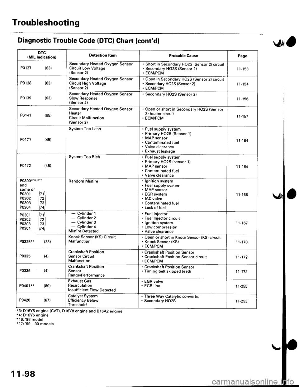
DTClMlL indicationlDatection hsmProbablo CausePage
P0137(63)Secondary Heated Oxygen SensorCircuit Low Voltage(Sensor 2)
Short in Secondary HO2S lSensor 2) circuitSecondary H02S {Sensor 2)ECM/PCI\41 1-153
P0r38 {63)Secondary Heated Oxygen SensorCircuit High Voltage(Sensor 2)
Open in Secondary HO2S (Sensor 2) circuitSecondary HO2S (Sensor 2)EC[I/PCM11-154
P0'139 (63)Secondary Heated Orygen SensorSlow Response(Sensor 2)
Secondary H02S lSensor 2)1l-156
P0141 (65)
Secondary Heated Oxygen SensorHeaterCircuit Malfunction(Sensor 2)
. Open or short in Secondary HO2S (Sensor2) heater circuit. ECM/PCM11-157
P0171 (45)
System Too LeanFuel supply systemPrimary HO2S (Sensor 1)MAP sensorContaminated fuelValve clearanceExhaust leakage
11,164
P0172 (45)
System Too RichFuel supply systemPrimary HO2S (sensor l)MAP sensorContaminated fuelValve clearance
11-164
P0300*16' }l?
andsome ofPo3o1 /r'' \P0302 l72lP0303 l73lP0304 \7 4l
Random Misfirelgnition systemFuel supply systemMAP sensorEGR systemIAC valveContaminated fuelLack of fuel
r1-r66
P0301P0302P0303P0304
/rt\172ll73l\7 4l
- Cylinder 1- Cylinder 2- Cylinder 3- Cylinder 4Misfire Detected
Fuel InjectorFuel Injector circuitlgnition systemLow compressionValve clearance
11 167
P0325*3 (23)Knock Sensor (KS) CircuitMalfunctionOpen or short in Knock Sensor (KS) circuitKnock Sensor {KS)ECM/FCtvl11-170
P0335(4)Crankshaft PositionSensor CircuitMalfunction
Crankshaft Position SensorCrankshaft Position Sensor circuitECM/PCM11-172
P0336(4)Crankshaft PositionSensorRange/Performance
. Crankshaft Position Sensor. Timing belt skipped teeth11-172
P040'�r*r (80)Exhaust GasRecirculationInsufficient Flow Detected
' EGR valve. EGR line
P0420(67)Catalyst SystemEfficiency BelowThreshold
. Th.ee Way Catalytic converter. Secondary HO2S11 253
Diagnostic Trouble Code (DTCI Chat (cont'dl
*3: D16Y5 engine (CVT), D16Y8 engine and B1642 engine*4: D'16Y5 engine*16: '98 model+17: '99 - 00 models
,Jla
1 1-98
Page 368 of 2189
,'o
L
*:The E indicator light and the Maltunction Indicator Lamp (MlL) may come on simultaneously.*1: D16Y5 engine (CVT)"5: '96 D16Y5 engine, D16Y7 engine, D16Y8 engine (sedan).'97 D16Y5 engine, Dl6Y7 engine (coupe: KA, KC models, sedan: KA.
KC, KL (DX) models, hatchback: all models), D16Yg engjne (sedan: KA, KC models)*6: '96 D16Y8 engine (coupe),'97 Dl6Y7 engine (coupe: KL model, sedan: KL (LX) model),'97 D'16Y8 engine (coupe: all models,
sedan: KL model),'98-all models,'99-all models,'00-all models*12: Except A,,/T (D16Y7, D16Y8 enginei*13: A"/T (D16Y7, D16Y8 engine)!l*14:'97 model*16:'98 model" 17: '99 - 00 models
(cont'd)
1 1-99
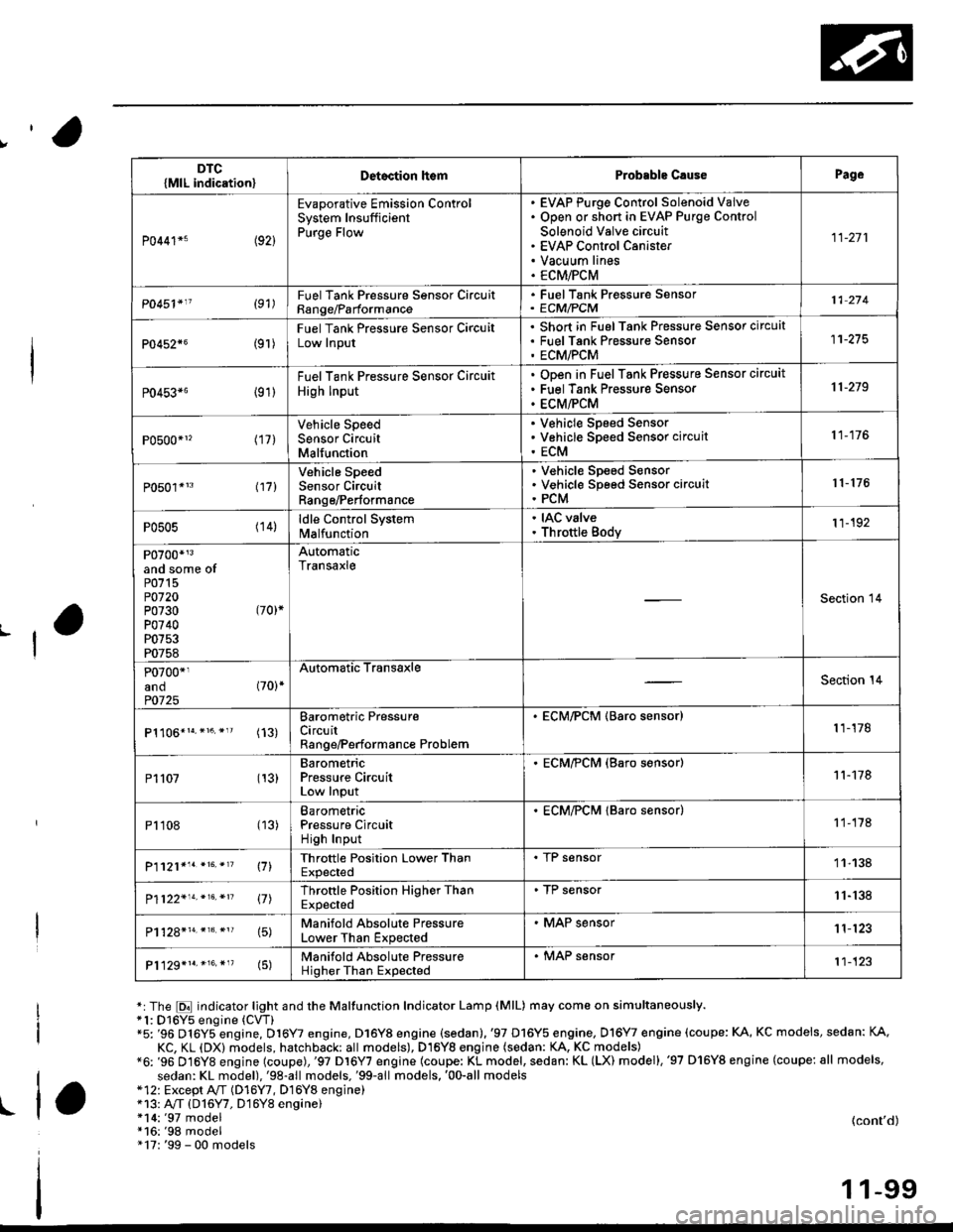
DTC{MlL indication}Detoction lt€mProbable C.usePage
P0441*5 (92)
Evaporative Emission ControlSystem InsufficientPurge Flow
EVAP Purge Control Solenoid VaiveOpen or short in EVAP Purge Control
Solenoid Valve circuitEVAP Control CanisterVacuum linesECM/PCM
11-271
P0451'11 (91)FuelTank Pressure Sonsor CircuitRange/Parformance
. FuelTank Pressure Sensor' ECM/PCM11 274
P0452{6(9r )
Fuel Tank Pressure Sensor CircuitLow Input
Short in FuelTank Pressure Sensor circuatFuel Tank Pres$ure SensorECM/PCM
11-275
P0453*6 {91)
Fuel Tank Pressure Sensor Circuit
High Input
ODen in Fuel Tank Pressure Sensor circuit
Fuel Tank Pressure Sensor
ECM/PCM
11-219
P0500*1, (17)Vehicle SpeedSensor CircuitMalfunction
V€hicle Speed SensorVehicle Speed Sensor circuit
ECM
11-176
P0501*'3 l17l
Vehicle SpeedSensor CircuitRange/Performance
V€hicle Sp€ed SensorVehicle Speed Sensor circuitPCM
r 1- 176
P0505 (14)ldle Control Systemlvl a lfu n ctio n
. IAC valve. Throttle Body11-192
P0700*r3and some ofP0715P0720P0730 (70)*
P0740P0753P0758
AutomaticTransaxle
Section 14
P0700*1and (70)*
P0725
Automatic TransaxleSection 14
(13)Barometric PressureCircuitRange/Performance Problem
. ECM/PCM (Baro sensor)1 1-178
P1107 (13)BarometricPressure CircuitLow Input
. ECM/?CM (Baro s€nsor)11-178
P1108 (13)BarometricPressure CircuitHigh Input
. ECM/PCM lBaro sensor)1 1-178
P1121*'. *16. *'? \71Throttle Position Lower ThanExpected
. I r sensor11-138
P1122'14.*16.*n 17lThrottle Position Higher ThanExpected
. TP sensor11-'138
15)Manifold Absolute PressureLower Than Expected
. MAP sensor1 1'123
P1129*1r.*16.*"(5)Manifold Absolute PressureHigher Than Expected
. MAP sensor't1-123
Page 369 of 2189

Troubleshooting
Diagnostic Trouble Code (DTGI Chart (cont'dl
*7: D16YS engine (M/T)*8: D16Y5, D'16Y8 engine*9: USA model*14r'97 model*15r '96 model
DTC(MlL indicationlDetection lt6mProbablc CausePage
P1162+1 (48)Primary Heated Oxygen Sensor(Sensor 1) CircuitMalfunction
Open or short in Primarv HO2S (Sensor 1Primary H02S (Sensor 1)1 1- 146
P]163' (61)Primary Heated Oxygen Sensor(Sensor '1) CircuitSlow Response
. Primary HO2S (Sensor 1)
11-145
Pl164*r (61)Primary Heated Oxygen Sensor(Sensor l) Cjrcuit Range/Performance Problem
. Primary HO2S (Sensor 1)
1 1- 150
P1165*? (61)Primary Heated Oxygen Sensor(Sensor 1) Circuit Range/Performance Problem
. Primary HO2S (Sensor 1)
11-150
P1166' (41i
Primary Heated Oxygen Sensor(Sensor '1) Heater System ElectricalProblem
Open or short in Primary HO2S (Sensor 1)heater circuitPrimary HO2S (Sensor 1)ECM/PCM
1 1-'161
P1167*' (41)Primary Heated Oxygen SensorlSensor 1) Heater SystemMalfunction
Open in Primary HO2S (Sensor 1) VS+ circuitPrimary HO2S (Sensor 1) HeaterPrimarv HO2S {Sensor 1)1 1- 163
P1168*' (48)Primary Heated Oxygen Sensor(Sensor 1) LABEL Low Input
. Short in Primary HO2S (Sensor 1) LABELcircuit11-151
Pl169*? (48)
Primary Heated Oxygen Sensor(Sensor 1)IABEL High Input. Open in Primary HO2S (Sensor 1)IABELcircuit. Short in ground circuit11.152
P1259*3(221
WEC System MalfunctionWEC Solenoid ValveOpen or short in WEC SolenoidValve circu itVTEC Pressure SwitchOpen or short in VTEC Pressure SwitchcircuitECM,FCM
Section 6
P1297*s (20)Electrical LoadDetector CircuitLow Input
Electrical Load DetectorElectrical Load Detector circuitECM/PCM11-179
Pr298+' l20l
Electrical LoadDetector CircuitHigh Input
Electrical Load DetectorElectrical Load Detector circuitECM/PCM1 1-181
anosome ofP0301P0302P0303P0304
l71ll72ll73ll7 4l
Bandom Misfirelgnition systemFuel supply systemMAP sensorEGR systemIAC valveContaminated fuelLack ol fuel
11-166
1 1-100
Page 371 of 2189
Troubleshooting
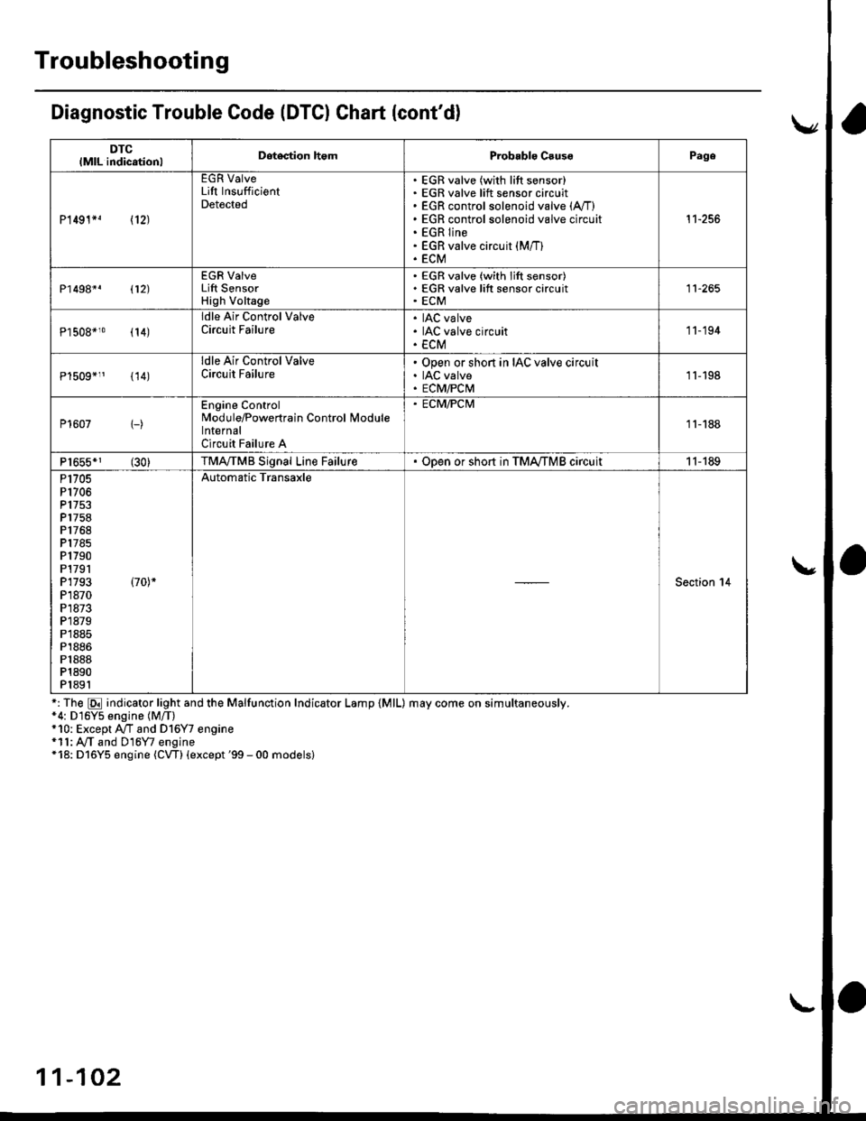
Diagnostic Trouble Code (DTCI Ghart (cont'd)
DTClMlL indicationlDetegtion homProbablo CsussPage
P1491*! \12J
EGR ValveLift InsufficientDetected
EGR valve (with lift sensor)EGR valve lift sensor circuitEGR control solenoid valve (A,/I)
EGR control solenoid valve circuitEGR lineEGR valve circuit (M/T)
ECM
't1-256
P1498*. 112)
EGR ValveLift SensorHigh Voltage
EGR valve (with lift sensor)EGR valve lift sensor circuitECM11-265
Pl508*10 (14)
ldle Air Control ValveCircuit FailureIAC valveIAC valve circuitECM
'11-194
{14)
ldle Air Control ValveCircuit FailureOpen or short in IAC valve circuitIAC valveECM/PCM1l-198
P1607 1-)
Engine ControlModule/Powertrain Control lvlodulelnternalCircuit Failure A
. ECM/PCM
11-188
P1655*1 (30)TMA,/TMB Signal Line FailureODen or sho.t in TMA,/TMB circuit11-189
P1705P1706P 1753P1758P1768P1785P1790P1791P1793 (70)*
P1870P1873P1879P1885P1886P1888P1890P1891
Automatic Transaxle
Section 14
*: The E indicator light and the Malfunction Indicator Lamp {MlL) may come on simultaneously.*4: D16Y5 engine (M/T)+10: Except A/T and Dl6Y7 engine*11: A,/T and D16Y7 engine*18: D16Y5 engine (CW) (except '99 - 00 models)
11-102
Page 410 of 2189
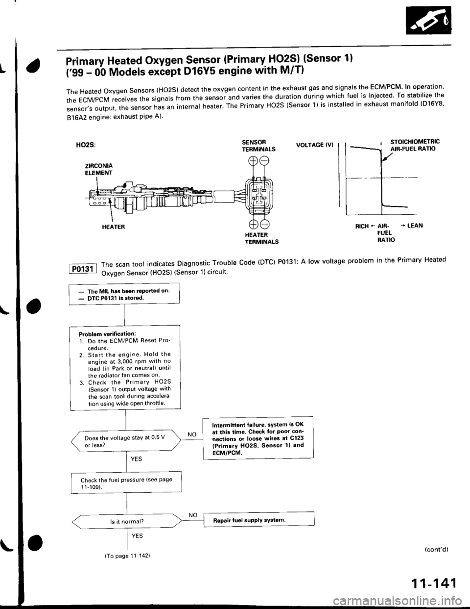
Primary Heated Oxygen Sensor (Primary- Fjq?S) (Sensor 1l
('99 - 0b Models exiept D16Y5 engine with M/T)
TheHeatedoxygensensors(Ho2S)detecttheoxygencontentintheexhaustgasandsigna|stheEcM/PcM'|noperation,
the EcM/pcM receives the signars from the sensor and varies the duration during which fuel is injected. To stabilize the
sensor,soutput,thesensornasaninternaIheater.ThePrimaryHo2S(sensorl)isinsta|ledinexhaustmanifo|d(D16Y8.
81642 engine: exhaust PiPe A)
SENSORTERMINALSVOLTAG€ (VI
HEATERTERMINALS
The scan tool indicates Diagnostic Trouble Code (DTC) P0131: A low voltage
Oxygen Sensor (HO2S) (Sensor 1) circuit
RICH+ AIR- - LEANFUELRATIO
problem in the Primary Heated
HEATER
- The MIL has been t€Ported on.- DTC P013'l is stored.
Problem veritication:1. Do the ECM/PCM Reset Pro-
2. Start the engine. Hold the
engine at 3,000 rpm wrth no
load (in Park or neutral) until
the radiator fan comes on
3. Check the PrimarY HO2S
lSensor 1) output voltage wath
the scan tool during accelera
tion using wide open throttle
lntermittont f.ilure, 3ystem i3 OK
at thi3 time. Check tor Poor con'
nections or loose wires el C123
{Primary HO2S, Sensor 1) and
ECM/PCM.
Does the voltage stay at 0 5 v
or less?
Check the fuel pressLlre (see Page11,109).
(To page 11 142)(cont'd)
11-141
Page 421 of 2189
PGM-FI System
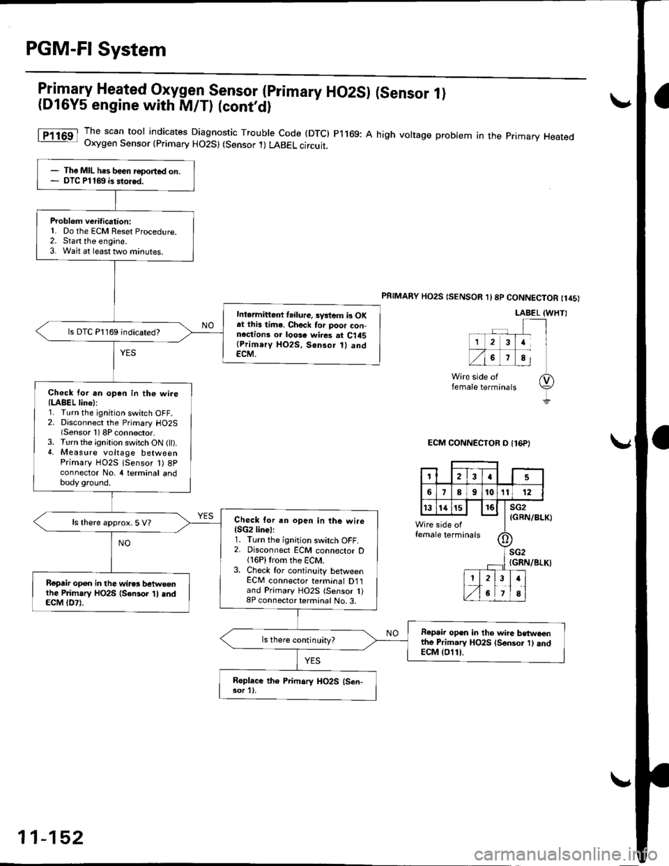
IiT-"-w Heated 9{ygglSensor (primary HO2SI (Sensor 1)(Dl6Y5 engine with M/Tl lconr'd)
1T1163 Ih" scan tool indicates Diagnostic Trouble code (DTc) P1169: A high volrage probtem in the pnmary Heated- Uxygen Sensor {primary HO2S) (Sensor .l) LABEL circuit.
PSTMARY HO2S (SENSOR 1l8p CONNECTOR (145)
LABEL IWHTI
ECM CONNECTOR O {16P}
(GRN/BLK)
female
IGRN/BLKI
- The MIL hrs been reported on.- DTC Pl169 i3 stored.
Problem verification:L Do the ECM Reset Procedure.2. Start the engine.3. Wait at least two minutes.
Intormittent f.ilure, sv*em b OKat this time. Check for poor con-n.ctions or loose wires at C145(Prim.ry HO2S, Sensor 1l andECM.
ls DTC P1169 indicated?
Ch€ck Ior an op6n in th€ wire(LABEL line):1. Turn the ignition switch OFF.2. Disconnect the Primary HO2S(Sensor 1) 8P connector.3. Turn the ignition switch ON (ll).4. Measure voltage betweenPrimary HO2S lsensor 1) 8Pconnector No, 4 terminal andbody ground.
Check lor an open in the wire{SG2linel:1. Turn the ignition swilch OFF.2. Disconnect ECM connector D(16P)trom the ECM.3. Check for continuity betlveenECM connector terminal D1land Primary HO2S (Sensor 1)8P connector terminal No. 3.
ls there approx. 5 V?
Ropair opon in the wires betweonlhe P.imary HO2S {Sensor 't} andECM tD7l.
R€pair open in th6 wire betweenthe Primary HO2S lsensor 1) andECM (011).
ls there continuity?
Roplace the Primary HO2S (Sen-sor 1).
123a5
689101t12
t3141516sG2
side ofe terminalstll
II-- rl
;G2
I2
6
34
8
11-152
Page 458 of 2189

[F16551l Th" ""un toot indicates Diagnostic Trouble Code (DTC) P1681: TIVA,/TMB signal line failure
Problem verification:1. Do the ECM Reset Procedure.
2. Drive the vehicle Ior several
miles at varying speeds
lnt.rmittent failure, system is OK
at ihis time. Check tor Poor con-
nections or loos€ wires at C131
llocated under right side of dash),
C438 ITCM) and ECM.
ls DTC P1655 indicated?
Check lor an oPen in the wire(TMA line):1. Turn the ignition switch OFF
2. Disconnect ECM connector C(31P)from the ECM
3. Turn the ignition switch ON (ll).
4- Measure vo ltag e between
ECM connector terminal Cg
and body ground.
Check for a short in the wire
ITMA line,:Measure voltage between TCM
22P connector terminal No 7 and
body ground.ls there battery vohage?
Ropair shod in the wire bstwe€n
the EcM (C!l) and the TcM.ls there battery voltage?
Check for an open in the wire
{TMB line}:1. Turn the ignition switch OFF
2. Reconnect ECM connector c(31P).
3. Disconnect the 22P connector
from TCM.4. Turn the ignition switch ON (ll).
5. Measure vo ltage between
TCM 22P connector termlnal
No. 6 and body ground.
Repair open in the wire between
th€ EcM {Ca) and the TcM.
Check for a 3ho.t in the wire
{TMB lin6,:Measure voltage between ECM
connector terminal C30 and bodyground,
ls there battery voltage?
Substitute a known'good ECM
and recheck. It symPtom/indica'tion goes away, teplace the origi-
nal ECM.
Reoair short in the wile b6tween
the ECM {C30} and the TCM.ls there baftery voltage?
f,epair open in the wire between
the EcM (C30) and the TcM.
IJA/T Signal (TMA/TMBI ('96 - 98 Dl6Y5 engine with GW)
ECM CONNECTOR C 131P}TMA IGRYI
fcu22PCONNECTOR
ll
TMB*{PNK}
231678910
1t'12131415161718
232a252930
Wire side oI temale
terminals
tl,
1 1-189