Page 1259 of 2189
tInstallation
Using a knife, scrape the old adhesive smooth to a
thickness of about 2 mm (0.08 in.) on the bonding
surface around the entire windshield opening flange.
NOTE:
. Do not scrape down to the painted surface of the
body; damaged paint will interfere with proper
bonding.
. Remove the rubber dams and tasteners from the
body.
. Mask off surrounding surfaces before painting.
Clean the body bonding surface with a sponge damp-
ened in alcohol.
NOTE: After cleaning, keep oil, grease and water
from getting on the surface.
lf the old windshield is to be reinstalled, use a putty
knife to scrape off all traces of old adhesive, then
clean the windshield surface with alcohol where
new adhesive is to be applied.
NOTE: Make sure the bonding surface is kept free
of water, oil and grease.
CAUTION: Avoid setting the windshield on its edges;
small chips may later deyelop into cracks.
NOTE:
. Clean the shadowed area.
o Clean area @ as shown.
lnside
&
'1.
2.
3.
Ct
a4)
)
WINDSHIELD
JWINDSHIELD
20-29
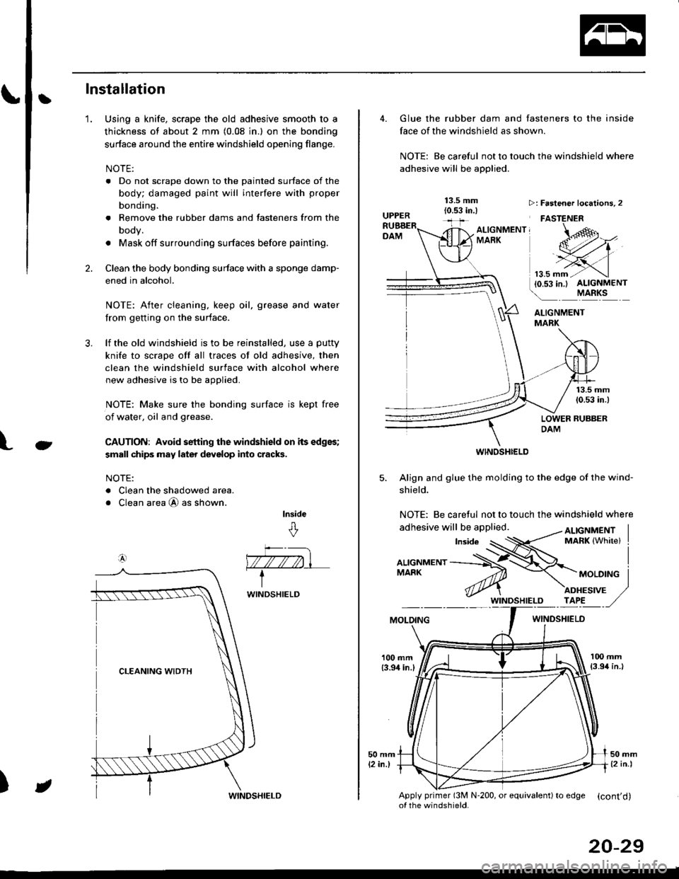
Glue the rubber dam and fasteners to the inside
face of the windshield as shown.
NOTE: Be careful not to touch the windshield where
adhesive will be applied.
ALIGNMENTMABK
13.5 mm(0.53 in.)
LOWER RUBBERDAM
WINOSHI€LD
5. Align and glue the molding to the edge of the wind-
shield.
NOTE: Be caretul not to touch the windshield where
>: Faslener localions, 2
FASTENER
ALTGNMENT, -oMARK
MOLOINGWINDSHIELO
100 mm{3.94 in.l
Apply primer (3M N'200, or equivalent) to edSe (cont'd)of the windshield.
Page 1263 of 2189
Ilnstallation
Using a knife, scrape the old adhesive smooth to a
thickness of about 2 mm (0.08 in.) on the bonding
surface around the entire rear window opening
flange.
NOTE:
. Do not scrape down to the painted surface of the
body; damaged paint will interfere with proper
bonding
o Mask off surrounding surfaces before painting.
. Remove the fasteners and spacers from the
oooy.
Clean the body bonding surface with a sponge
dampened in alcohol.
NOTE: After cleaning, keep oil. grease and water
from getting on the surface.
lf the old rear window is to be reinstalled, use a putty
knife to scrape off all traces of old adhesive and the
rubber dam, then clean the rear window surface with
alcohol where new adhesive is to be applied.
NOTE: Make sure the bonding surface is kept free
of water, oil and grease.
CAUTION: Avoid setting the rear window on its
edges; small chips may later develop into cracks.
NOTE: Clean the shadowed area.
1.
2.
)
)
REAR WINDOW
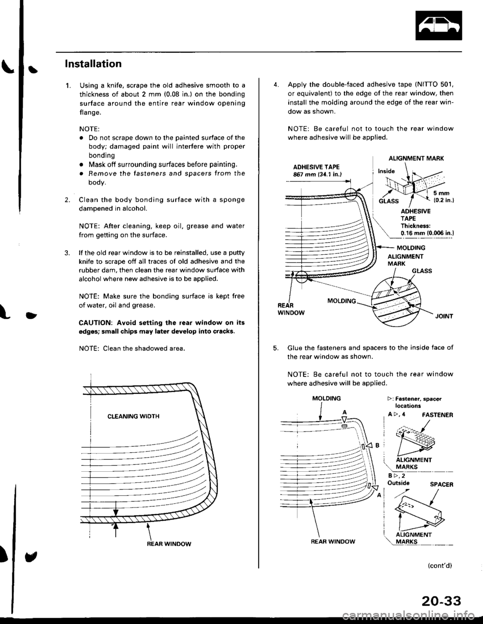
4. Apply the double-faced adhesive tape (NITTO 501,
or equivalent) to the edge of the rear window, then
install the molding around the edge of the rear win-
dow as shown.
NOTE: Be careful not to touch the rear window
where adhesive will be applied.
ADHESIVE TAPE867 mm 134. I in.)
5mm{0.2 in.}
ADHESIVETAPEThickness:0.16 mm (0.006 in.l
GLASS
MOLDING
wtNoow
Glue the fasteners and spacers to the inside face of
the rear window as shown.
NOTE; Be careful not to touch the fear window
where adhesive will be applied.
5.
MOLDING
ALIGNMENTMARK
T ALIGNMENT
!
aRKsa >,2Outside
>:Fa3l€ner, spacerlocations
A >, 4 FASTENER
(:r:^#-
ry
I liGrtrrrrertrr\..!44llc-''' - -
SPACER
(cont'd)
20-33
ALIGNMENT MARK
REAR WINOOW
MOLOING
Page 1330 of 2189
Trunk Lid/Hatch
WeatherstripLicense Plate Trim
Replacement
When installing the trunk lid/hatch weatherstrip. align it
with the alignment mark on the trunk lid/hatch opening.
NOTE:
. Make sure there are no wrinkles in the weatherstrip.
. Check for water leaks.
2DllDi
STEEI.CORE
3D:
ALIGNMENTMARK (2Dl4D)
ALIGNMENT MARK
WEATHERSTRIP
ALIGNMENT MARK
BODY
\
20-100
Replacement
CAUTION: Put on glov€s to plotest your hands.
NOTE: Take care not to scratch the trunk lid/hatch.
1. Remove the license plate.
2, 3D: Remove the hatch trim panel (see page 20-63).
3. Remove the nuts and clips, and detach the clip, then
remove the license plate trim.
NOTE: Take care not to drop the nuts inside the trunk
lid/hatch.
a: Nut locations,2
6fi\5x0.8mm Irvr?// 1,8 N.m {0.18 kst.m,l- j llrftl ,/
>: Clip locations,
InA
aa# )
-,/
Installation is the reverse of the removal orocedure.
NOTE: lf necessary, replace any damaged clips.
Page 1460 of 2189
Compressor (SANDENI
Thermal Protestor Replacement
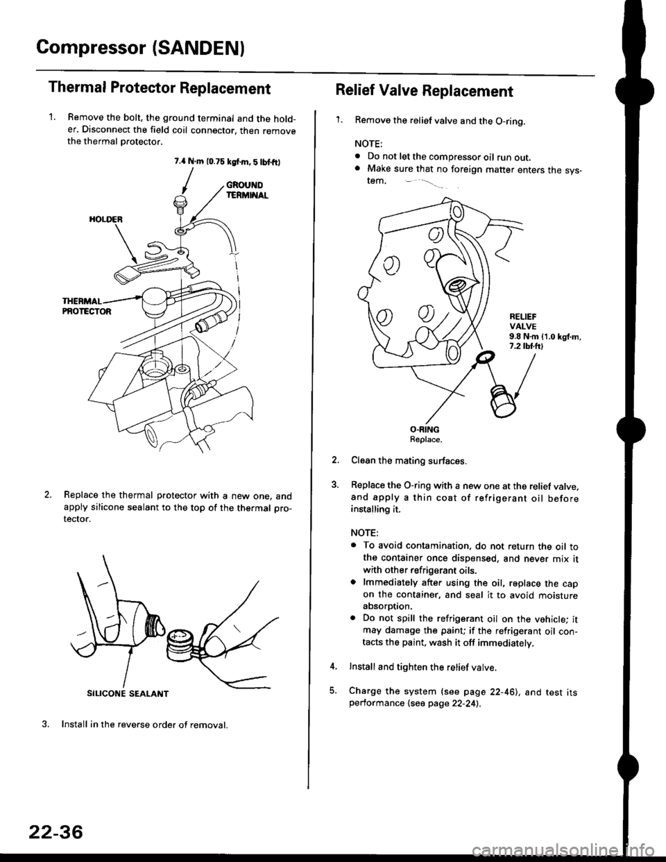
1. Remove the bolt, the ground terminal and the hold-er. Disconnect the field coil connector. then removethe thermal Drotector.
7.{ N.m 10.75 ksf.m,5lbtfr)
/
SILICONE SEALANT
3. Install in the reverse order of removal.
GROUNDIERMINAL
HOI.I'ER
PNOTECTOR
Replace the thermal protector with a new one. andapply silicone sealant to the top of the thermal pro-
tector.
22-36
oo
Relief Valve Replacement
'1.Remove the relief valve and the O-ring.
NOTE:
. Do not let the compressor oil runout.. Make sure that no foreign matter enters the sys-tem,
RELIEFVALVE9.8 N.m {1.0 kgl.m,7.2 tbl.lrl
O.RINGReplace.
Clean the mating surfaces.
Replace the O-ring with a new one at the relief valve.and apply a thin coat of refrigerant oil beforeinstalling it.
NOTE:
. To avoid contamination. do not return the oil tothe container once dispensed, and never mix it
with other refrigerant oils.o lmmediately after using the oil, replace the capon the container, and seal it to avoid moistureabsorption.
. Do not spill the refrigerant oil on the vehicle; itmay damage the paint; if the refrigerant oil con-tacts the paint, wash it off immediately.
Install and tighten the relief valve.
Charge the system {see page 22-461, and test itsperformance 1se6 page 22-241.
Page 1462 of 2189
Compressor (DENSOI
Replacement (cont'd)
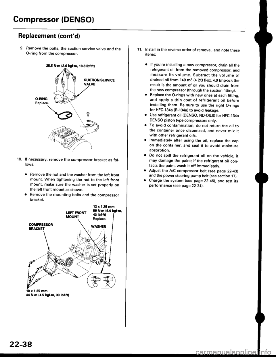
9. Remove the bolts, the suction service valve and theO-ring from the compressor,
lf necessary, remove the compressor bracket as fol-lows.
. Remove the nut and the washer from the left frontmount. When tightening the nut to the left frontmount, make sure the washer is set p.operly onthe left front mount as shown.
a Remove the mounting bolts and the compressor
bracket.
12 x 1,25 rnm59 N.m 16.0 kgfrm,
10.
LEFT FRONTMOUNT€ rbf.fi)Roplace.
WASHEB
x 1.25 mm
2s.5 N.m {2.6 kgf.m. 18.8 tbtttl
4/r N.m {4.5 kgf.m, 33 lbt ft}
22-3A
1 1. Install in the reverse order of removal, and note thesertems:
lf you're installing a new compressor. drain all therefrigerant oil from the removed compressor. andmeasure its volume. Subtract the volume ofdrained oil from '140 ml (4 28 fl{,z, 4.9 lmpoz); theresult is the amount of oil you should drain fromthe new compressor (through the suction fifting).Replace the O-rings with new ones at each fining,and apply a thin coat of refrigerant oil beforeinstalling them. Be sure to use the right O,ringsfor HFC-134a (R-134a) to avoid leakage.
Use refrigerant oil {DENSO, ND-OtL8) for HFC-134aDENSO piston type compressors only.To avoid contamination, do not return the oil tothe container once dispensed, and never mix itwith other refrigerant oils.
lmmediately after using the oil, replace the capon the container, and seal it to avoid moisture
absorption.
Do not spill the refrigerant oil on the vehicle; itmay damage the paint; if the refrigerant oil con-tacts the paint, wash it off immediatelv.
Adjust the ly'C compressor belt (see page 22-43)and the power steering pump belt (see section 17).Charge the system (see page 22-46), and test itsperformance (see page 22-24!..
Page 1498 of 2189
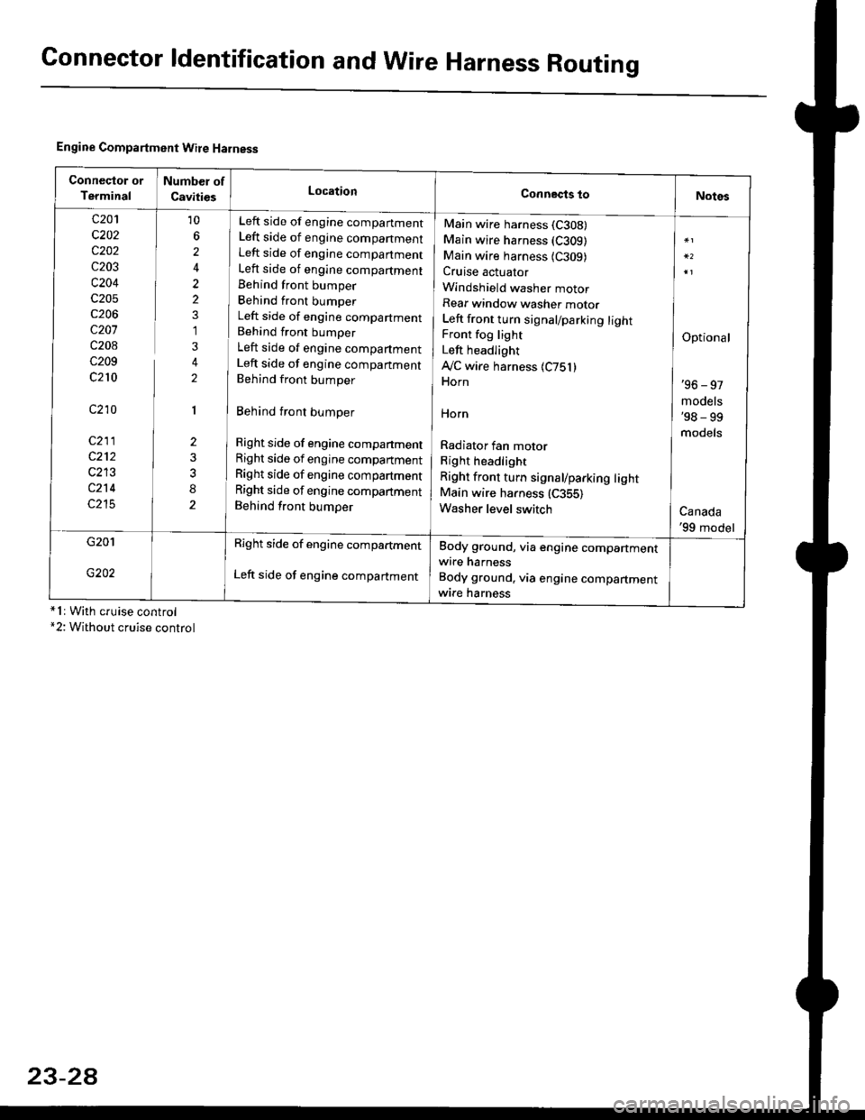
Connector ldentification and WireHarness Routing
Engine Compartment Wire Harness
conneqtor of
Terminal
Number of
CavitiesLocationConnects toNotes
c201
c202
c202
c203
c204
c205
c206
c207
c208
c209
c210
c210
c211
c212
c213
c214
c215
10
6
2
2
2
1
3
2
1
2
8
Left side of engine companment
Left side of engine companment
Left side of engine companment
Left side of engine compartment
Behind front bumper
Behind front bumper
Left side of engine compartment
Behind front bumper
Left side of engine compartment
Left side of engine companment
Behind front bumper
Behind front bumper
Right side of engine compartment
Right side of engine compartment
Right side of engine compartment
Right side of engine compartment
Behind front bumper
Main wire harness (C308)
Main wire harness (C309)
Main wire harness {C309)Cruise actuator
Windshield washer motor
Rear window washer motor
Left front turn signal/parking lightFront fog light
Left headlight
Ay'C wire harness 1C751)Horn
HOrn
Radiator fan motor
Right headlight
Right front turn signal/parking lightMain wire harness (C355)
Washer level switch
Optional
'96 - 97
models'98 - 99
models
Canada'99 model
G201
G202
Right side of engine compartment
Left side of engine compartment
Body ground, via engine compartmentwire harness
Body ground, via engine compartmentwrre harness*1r With cruise control*2: Without cruise control
23-2A
Page 1607 of 2189
JBulb Locations {Without Tachometer)
TRUNK INDICATORLIGHT {1.i1W}
.4 Wl
CHARGING SYSTEM LIGHT 11,4 W}
LTGHT (1.4 W)GAUGE LIGHT
SEAT BELTREMINDER LIGHT (1.4 WI
LOW ENGINE OIL PRESSUBE
INDICATOB LIGHT (1.4 WI
LOW FUEL INDICATORLrGl{T (3 W)
RIGHT TURN SIGNALINOICATOR LIGHT
(1.1Wt
GAUGE LIGHTS {3 WI
WASHER LEVELINDICATOR LIGHT{1.4 W} lcanad.l
HIGH BEAMINDICATOR LIGHTMALFUNCTIONINDICATORLAMP (MIL)
BULB {1.4 WI
{1.ilW)
LEFT TURN SIGNALINDICATOR LIGHT {1.4 WI
A/T GEAR POSITIONINDICATOR (1.12 x 6)(On the printed
circuit board)
sRs TND|CATOR 11.4 W)
{On the Drinted circuit board}
aBs tNDtcAToR t1.4 W)(On the printed circuit board)(3.{ Wt
o/ o \7 o
23-137
Page 1719 of 2189
)Actuator Solenoid Test
1. Disconnect the 4P connector from the actuator'
ACTUATOR
2. Check for resistance between the terminals accord-
ing to the table.
NOTE: Resistance will vary slightly with tempera-
ture; sDecified resistance is at 70"F (20'C).
SAFETY VALVE
VACUUMVALVE
J
From VENTHOSE
+ To VACUUM
Terminalside otmale terminals
Terminal
Resistance (O) \
234
VENT SOLENOID40 600o---o
VACUUM SOLENOID30- 500G---o
SAFETY SOLENOID40- 600o---o
l)
TANK
23-249