Page 1753 of 2189
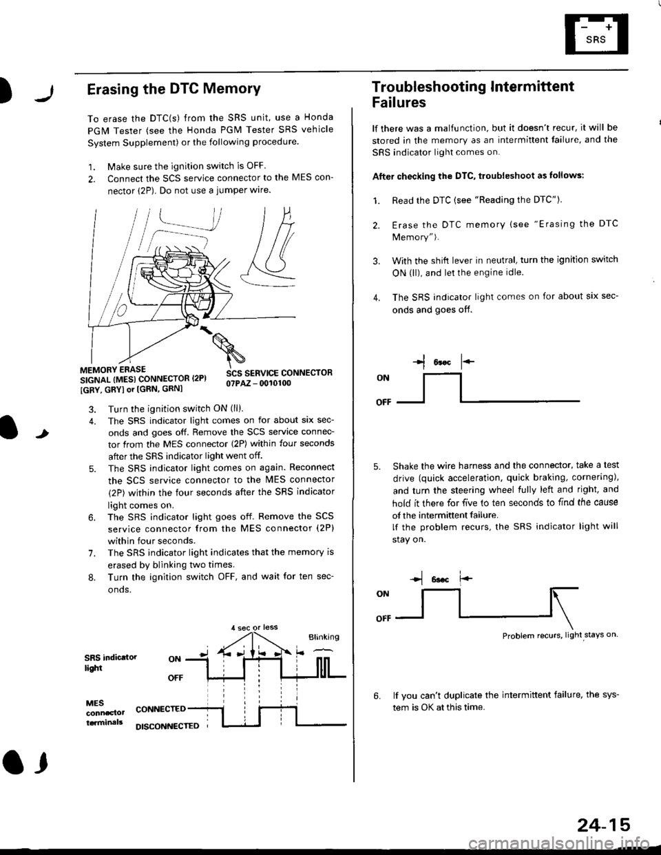
)Erasing the DTC Memory
To erase the DTC(s) from the SRS unit, use a Honda
PGM Tester (see the Honda PGM Tester SRS vehicle
System Supplement) or the following procedure
1. Make sure the ignition switch is OFF
2. Connect the SCS service connector to the MES con-
nector (2P). Do not use a jumper wlre.
]P,
&
.!--J
MEMORY ERASE
SIGNAL (MESI CONNECTOR I2PI
IGRY, GRYI or [GRN, GRNI
SCS SERVICE CONNECTORo?PAZ - 0010100
t
7.
Turn the ignition switch ON (ll).
The SRS indicator light comes on for about six sec-
onds and goes off. Remove the SCS service connec-
tor from the MES connector (2P) within four seconds
after the SRS indicator light went off.
The SRS indicator light comes on again. Reconnect
the SCS service connector to the lvlES connector
(2P) within the four seconds after the SRS indicator
light comes on.
The SRS indicator light goes off. Remove the SCS
service connector from the MES connector (2P)
within four seconds.
The SRS indicator light indicates that the memory is
erased by blinking two times.
Turn the ignition switch OFF, and wait for ten sec-
onos.
8.
SRS indictlorlighi
MESconncclottcaminals
CONNECTED
O,
DISCONI{ECTED
24-15
Troubleshooting Intermittent
Failures
lf there was a malfunction, but it doesn't recur, it will be
stored in the memory as an intermittent failure, and the
SRS indicator light comes on.
Afte. checking the DTC, troubleshoot as lollows:
1. Read rhe DTC {see "Reading the DTC"}.
Erase the DTC memory (see "Erasing the DTC
Memory").
With the shifi lever in neutral, turn the ignition switch
ON (ll), and lei the engine idle.
The SRS indicator light comes on for about six sec-
onds and goes off.
l*F
ON
tl-- -l
Shake the wire harness and the connector, take a test
drive (quick acceleration, quick braking, cornering),
and turn the steering wheel fully left and right, and
hold it there for five lo ten seconds to find the cause
of the intermittent failure.
lf the problem recurs, the SRS indicator light will
stay on.
-q 6a.c f'-
:q
Problem recurs, light stays on
3.
4.
6.lf vou can't duplicate the intermittent failure, the sys-
tem is OK at this time.
Page 1755 of 2189
l
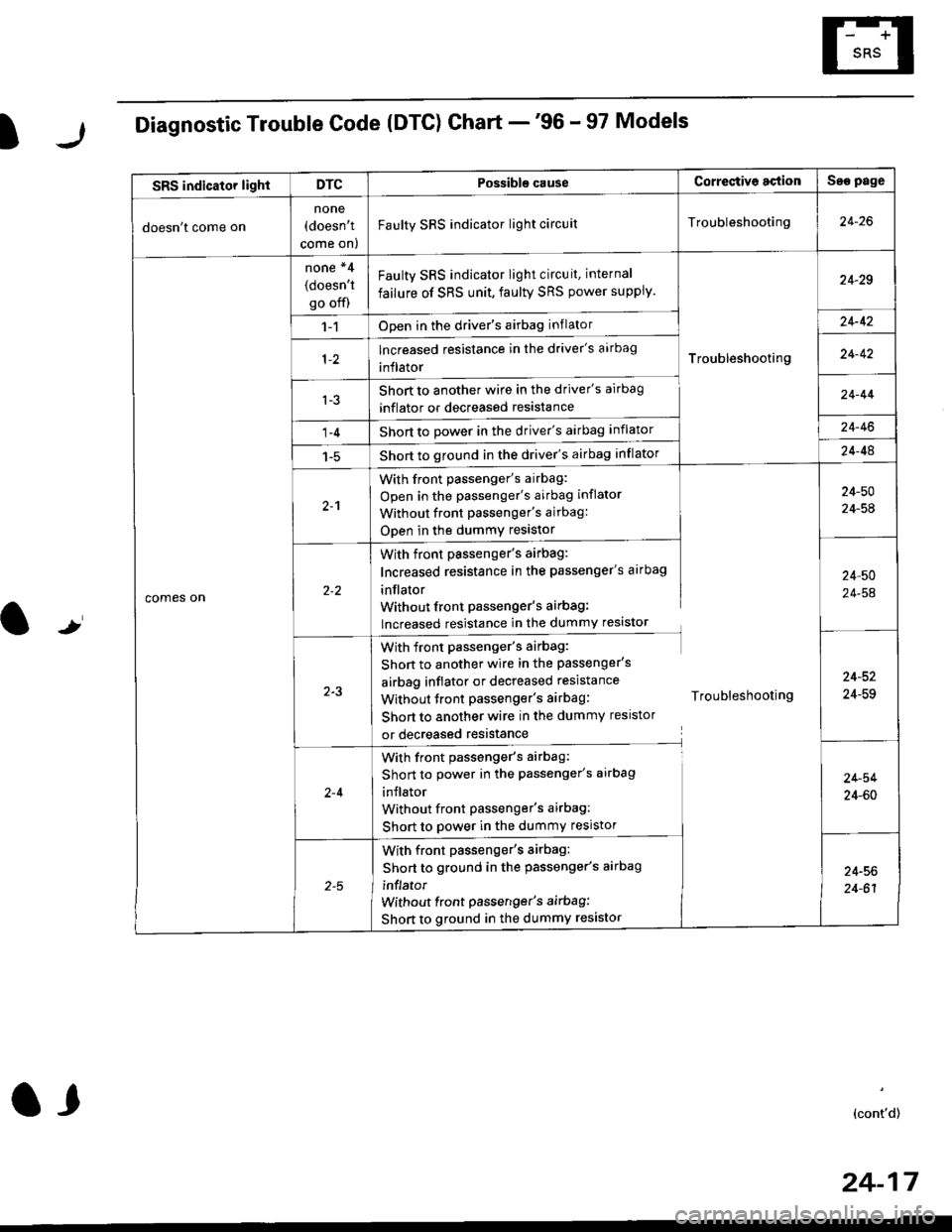
Diagnostic Trouble Code (DTG) Chart -'96 - 97 Models
t
SRS indicator lightDTCPossible causeCorrectiv6 actionSae page
doesn't come on
none(doesn't
come on)
Faulty SRS indicator light circuitTroubleshooting24-26
comes on
none *4
(doesn't
go off)
Faulty SRS indicator light circuit, internal
failure of SRS unit, faulty SRS power supply.
Troubleshooting
24-29
1-1Open in the driver's airbag inflator24-42
lncreased resistance in the driver's aarbag
inflator24-42
l-3Short to another wire in the driver's airbag
inflator or decreased resistance
Short to Dower in the driver's airbag inflator
Short to ground in the driver's airbag inflator
24-44
1-424-46
1-524-48
2-1
With front passenger's airbag:
Open in the passenger's airbag inflator
Without front Passenger's airbag:
ODen in the dummy resistor
24-50
24-54
With front passenger's airbag:
Increased resistance in the passenger's airbag
inflator
Without front Passenger's airbag:
lncreased resistance in the dummy resistor
24,50
24-54
2-3
With front passenger's airbag:
Shon to another wire in the passenger's
airbag inflator or decreased resistance
Without tront passenger's airbag: Troubleshooting
Short to another wire in the dummy resistor
or decreased resistance
24-52
24-59
2-4
With front passenger's airbag:
Short to power in the passenger's airbag
inJlator
Without front Passenger's airbag:
Short to power in the dummy resistor
24-54
24-60
With front passenger's airbag:
Short to ground in the passenger's aarbag
inflator
without front passenger's airbag:
Short to ground in the dummy resistor
24-56
24-61
(cont'd)
24-17
a,
Page 1756 of 2189
Troubleshooting
Diagnostic Trouble Code (DTCI Ghart -'96 - 97 Models (cont'd)
NOTE:* l: In case of an intermittent failure DTC g-1, it means there was an internal failure of the SRS unit or a faultv SRS indicator light circuit. Do the troubleshooting for intermittent failures (see page 24-15).*2: lt both DTC 9-2 and DTC 5-1 are indicated, do the troubleshooting for DTC g-2.*3: Apply to the '97 model coupe HX and DX.*4: DTC cannot be read with a Honda PGM Tester; check by jumping the SCS service connector.
24-18
.
Possiblg cause Cortestive action
5 3 I Internal failure of the SRS unitSRS unit
replacement
lnternal failure of the SRS unitSRS unit
replacement
Internal failure of the SRS unit
Internal failure of the SRS unitSRS unit
replacement
Internalfailure of the SRS unit ortwo failures at atime
8-6*3 Internalfailure ofthe SRS unit
Internal failure of the SRS unit
Faulty SRS power supply (VB line)
SRS unit replacement code (SRS unit must not
be used any longe.)
J
Page 1758 of 2189
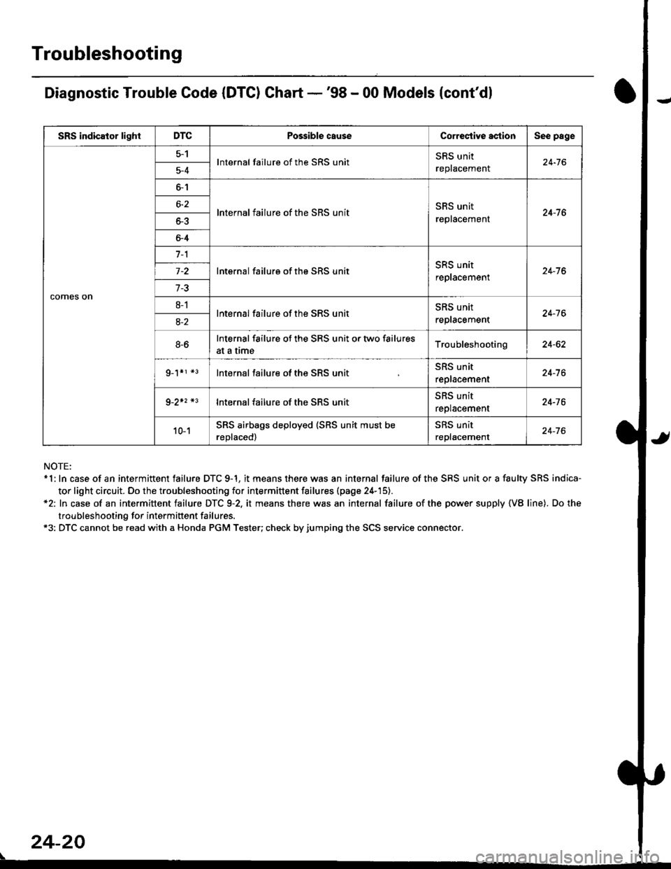
Troubleshooting
Diagnostic Trouble Code (DTC) Chart -'98 - 00 Models {cont'dl
NOTE:* 1: In case of an intermittent failure DTC 9-1, it means there was an internal failure of the SRS unit or a faulty SRS indica-
tor light circuit. Do the troubleshooting for intermittent failures (page 24-'15).*2: In case of an intermittent failure DTC 9-2, it means there was an internal failure of the power supply {VB line). Do the
troubleshooting for intermiftent failures.*3: DTC cannot be read with a Honda PGM Tester; check by jumping the SCS service connector.
24-20
\
SRS indicator lightDTCPossible causeCorrectiYe actionSee page
comes on
5-1lnternal failure of the SRS unitSRS unit
replacemenl24-765-4
6-1
lnternal failure of the SRS unitSRS unit
replacement24-7 66-2
o-5
6-4
7-1
lnternal failure of the SRS unitSRS unit
replacement24-76
7-3
8-1lnternal failure of the SRS unitSRS unit
reptacement24-7 68-2
8-6Internal failure of the SRS unit or two failures
at a trmeTroubleshooting24-62
g_1*r *3lnternal failure of the SRS unitSRS unit
replacement24-7 6
9-2+2 *3lnternal failure of the SRS unit5l|5 Untr
replacement24-76
10-1SRS airbags deployed (SRS unit must be
reDlaced)
SRS unit
replacement24-76
Page 1759 of 2189
)r
l,.l
I
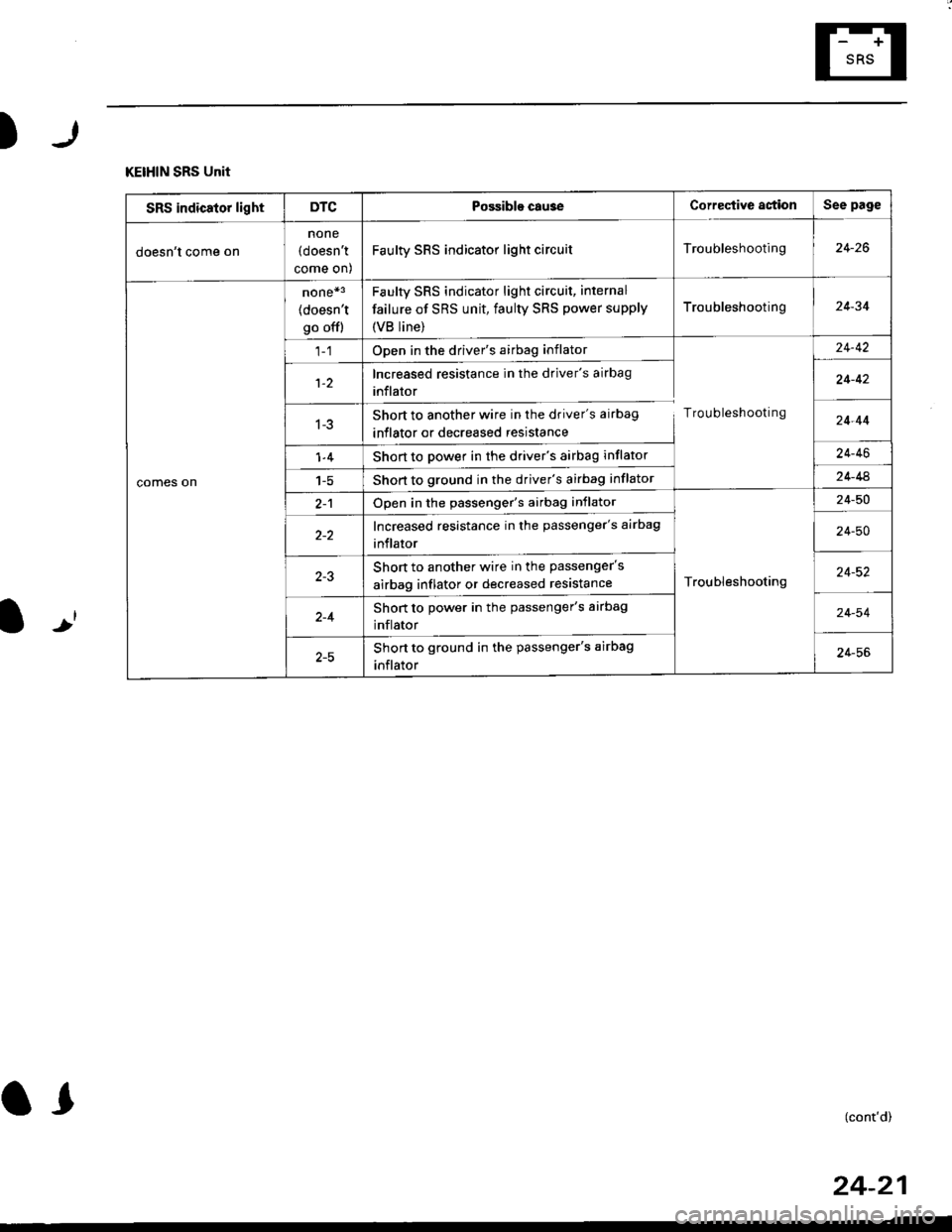
KEIHIN SRS Unit
SRS indicator lightDTCPossible cau3eCorrective astionSee page
doesn't come on
none
(doesn't
come on)
Faulty SRS indicator light circuitTroubleshooting24-26
comes on
none*3
(doesn't
go offl
Faulty sRs indicator light circuit, internal
failure of SRS unit, faulty SRS power supply
{VB line)
Troubleshooting24-34
Open in the driver's airbag inflator
Troubleshooting
24-42
1-2Increased resistance in the driver's airbag
inflator24-42
1-3Short to another wire in the driver's airbag
inflator or decreased resistance24-44
1-4Short to power in the driver's airbag inflator24-46
1-5Short to ground in the driver's airbag inflator24-44
2-1Open in the passenger's airbag inflator
Troubleshooting
24-50
Increased resistance in the passenger's airbag
inflator24-50
Short to another wire in the passenger's
airbag inflator or decreased resistance24-52
2-4Short to power in the passenger's airbag
inflator24-54
Short to ground in the passenger's airbag
inflator24-56
(cont'd)
24-21
Page 1760 of 2189
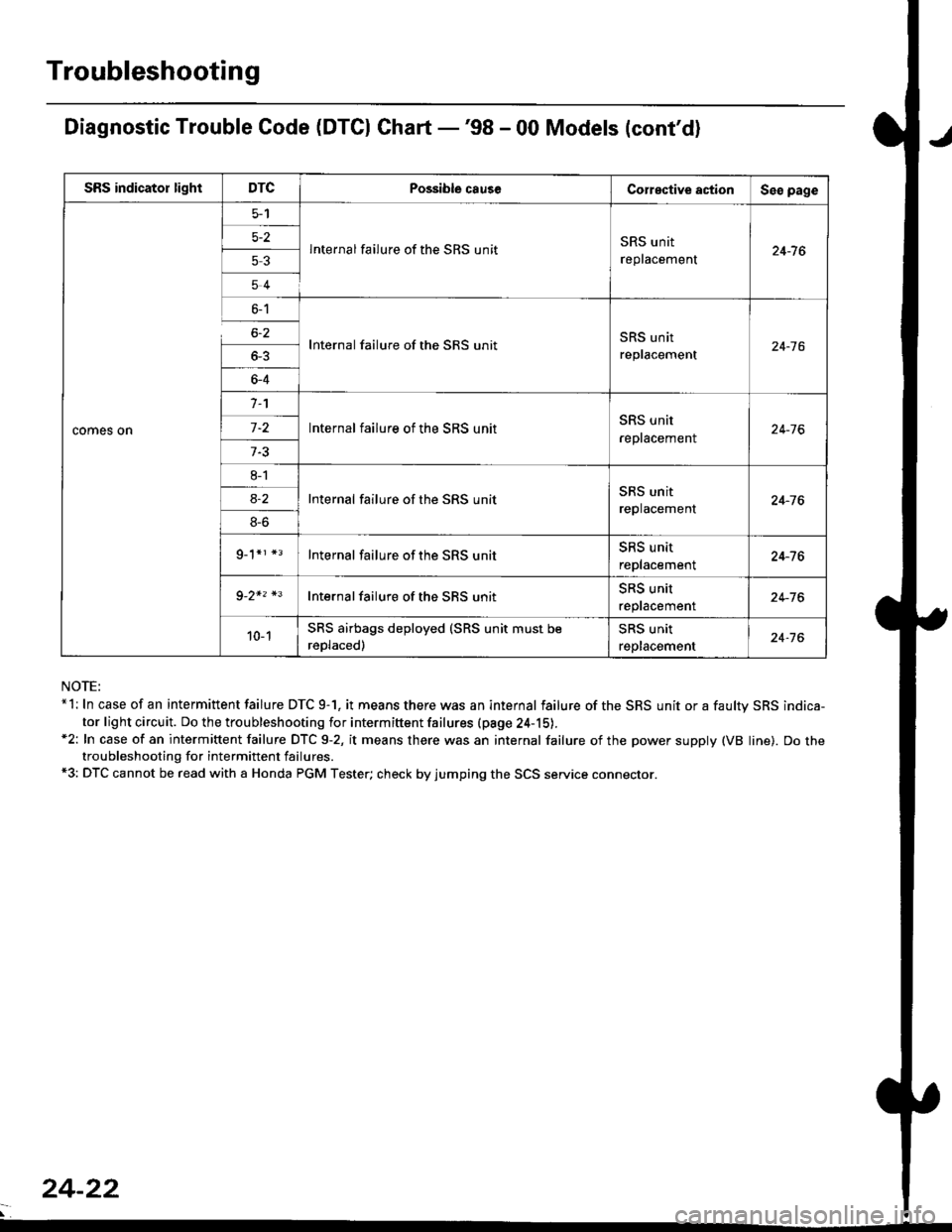
Troubleshooting
Diagnostic Trouble Code (DTCI Ghart -'98 - 00 Models (cont'd)
NOTE:*l: In case of an intermittent failure DTC 9-1. it means there was an internal failure of the SRS unit or a faultv SRS indica-
tor light circuit. Do the troubleshooting for intermiftent failures (pa9e 24-15).*2: In case of an intermittent failure DTC 9-2, it means there was an internal failure of the power supply (VB line). Do thetroubleshooting for intermittent failures.*3: DTC cannot be read with a Honda PGM Tester; check by jumping the SCS service connector.
SRS indicator lightDTCPossible causeCorective actionSeo page
comes on
5-2
53
54
lnternal failure of the SRS unitSRS unit
replacement24-7 6
6-1
6-2
_
64
Internal failure of the SRS unitSRS unit
replacement24-16
n
-
8l
8S
9_1*r *3
Internal failure of the SRS unitSRS unit
reptacement24-76
Internal failure of the SRS unitSRS unit
replacement24-76
Internal failure of the SRS unitSRS unit
replacement24-76
Internal failure of the SBS unitSRS unit
reptacemenr24-76
10-1SRS airbags deployed (SRS unit must be
reDlaced)
SRS unit
replacement24-76
24-22
Page 1762 of 2189
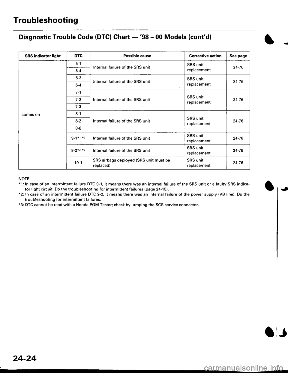
Troubleshooting
Diagnostic Trouble Code (DTG) Chart -'98 - 00 Models (cont'dl
NOTE:*'l: In case of an intermittent failure DTC 9-1. it means there was an internal failure of the SRS unit or a faulty SRS indica-
tor light circuit. Do the troubleshooting for intermiftent failu.es (page 24-15).*2: In case ot an intermittent failure DTC 9-2. it means there was an internal failure of the power supply (VB line). Do the
troubleshooting for intermift ent failures.*3: DTC cannot be read with a Honda PGM Tester; check by jumping the SCS service connector.
24-24
a,
SRS indicator lightDTCPossible causeCorective actionSee page
comes on
lnternal failure of the SRS unitSRS unit
repracemenl24-765-4
6-3lnternal failure of the SRS unitSRS unit
reptacemenr24-766-4
Internal failure of the SRS unitSRS unit
replacement24-7 6
8-1
lnternal failure ot the SRS unitSRS unit
replacement24-7 68-2
8-6
g_1*r *rInternal failure of the SRS unitSRS unit
replacement24-16
lnternal failure of the SRS unitSRS unit
repracemenl24-76
10-1SRS airbags deployed (SRS unit must be
.eplaced)
SRS unit
reptacemenl24-76
Page 1763 of 2189
SRS Indicator Light Wire Connections
SRS Indicator Light Power Circuit
DASHBOARD WIRE HARNESS
To UNDER-DASHFUSE/RELAY BOX -
20P CONNECTOR
SRS Indicato. Light Control Circuit
To SRS UNIT
tI
SRS MAIN HARNESS
C41 1, C412 : Terminal sido of mdlo t6rminalsC501, C5O2, C508, C801. C802, C807 : Wi.6 sidc of fomalo t.rminals
MAIN WIBE HARNESS
BLU
C508 -+ To GAUGE ASSEMBLY
c41 1
To GAUGE ASSEMBLY
at
C501 : DASHBOARDWIRE HARNESS 2oP CONNECTORC508 : DASHBOARD wlRE HARNESS 5P CONNECTORC801 : SRS MAIN HARNESS 2P CONNECTORC807 : SRS MAIN HARNESS 18P CONNECTOR
C802 : SRS MAIN HARNESS 3P CONNECTORC412 : MAIN WIRE HARNESS 3P CONNECTORC41 1 : MAIN WIRE HARNESS 24P CONNECTORC502 : DASHBOARD WIRE HARNESS 24P CONNECTOR
GRY
OI
24-25