Page 947 of 2189
Electrical Troubleshooting {'99 - 00 Models}
Troubleshooting Flowchart - A/T Gear Position Switch (Openl (cont'dl
Bepair opon in the wiro bgtw€enlho A22 torminal and the A/Tgoar poihion lwitch.
PCM CONNECTORS
B (25P1
LGT (BFN/ALK}
PCM CONNECTOR B I25PI
12.15 / 7I
9't0l1Br1/l/41it8
ll lLG2
o) (o)
IBRN/BLKI
Wire side of female terminals
From page 14-8-269
Msasuro ATP L Voftage:1. Shiftto E position.
2. Measure the voltage betweenthe A22 and 820 or 822 termi-nals,
Check LG Wiro for .n Open Cir-cuit:']� Turn the ignition switch OFF.2. Check lor continuity betweenthe 820 t€rminal and bodyground, and between the 822terminal and body ground.
Ropai' op.n in the wir€a botw.€nthe 820 rnd 822 toJminals .ndbody ground, and .opsi. poolground (Gl01l.
Check tor loose te.minal frt in th6PCM conn€ctors, lf n€cessary, sub-stitut€ a knowo-good PCM anda6check,
Wire side of female terminals
14-270
Page 948 of 2189

JTroubleshooting Flowchart - Shift Control Linear Solenoid
NOTE: Record all freeze data before you troubleshoot
Possiblc Cause
. Disconn€cted solenoid harnos3
connectol. Short or oDen in shilt controllinetr solonoid wiro. Faulty shift control linear sole_
noid. Op€n in VB SOL wite. ODen in PG'l and PG2 wires or
poor ground {G10'l)
f,
wire side ot female terminals
LG1 IBRN/BLKILG2IBRN/BLK)
{cont'd)
14-271
PCM CONNECTORS
B(25P) - Dll6P)
.OBD ll Scan Tool indicatos
Code P1870.. Solf-diagnosis E indic.lor light
indic.t€s Code 30.
M6a3ure VB SOL voltage:1. Turn the ignition switch OFF.
2. Disconnect the B 125P) and D(16P) connectors from the
PCM,3. Turn the ignition switch ON (ll).
4. Measure the voltage between
the D5 and 820 or 822 terminals.
Repair open or shod in the wire
between the D5 terminal and the
under-dash tuso/telay box.
Check the Ground Circuitl1. Turn the ignition switch OFF.2. Check lor continuity between
the terminafs 82 and 822 and
between terminals 810 and
820.
Repair open in the wi.e betwoen
the termin.ls 82, B10, B20, and
822 and G101. Repair Poolground (G101).
LG1 IBRN/BLKI
PCM CONNECTOR B PsPI
PG,I IBLK)
10 page 14-272
a
Page 949 of 2189
ElectricalTroubleshooting ('99 - 00 Models)
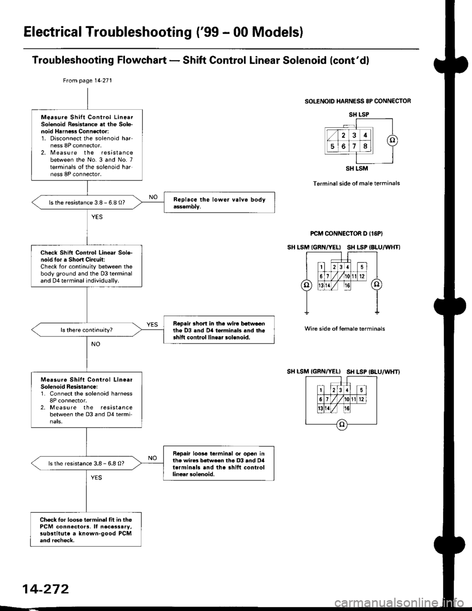
Troubleshooting Flowchart - Shift Gontrol Linear Solenoid (cont'dl
SOI."ENOID HARNESS 8P CONNECTOR
Terminal side of male terminals
PCM CONNECTOR D {16P}
SH LSM IGRN/YELI SH LSP {BLU/WHTI
Wire side oI temale terminals
SH LSM {GRN/YELI SH LSP IALU/WHT}
tuom page 14 271
Measure Shift Control LinearSolenoid R6sistance at the Sole-noid Hrrness Connector:1. Disconnect the solenoid harness 8P connector.2. Measure the resistancebetween the No. 3 and No- 7terminals oI the solenoid harness 8P connector,
ls the resistance 3.8 - 6.8 o?
Check Shift Control Lin€ar Sole-noid tor a Short Circuit:Check for continuity between thebody ground and the D3 terminaland D4 terminal individually.
Rep.ir short in th€ wir€ tr€twlrenihe D3 and D4 torminab .nd theshift cont.ol line.. solenoid.
Measure Shitt Conirol LineerSolenoid Resbtance:1. Connect the solenoid harness8P connector.2. Measure the resistancebetween the D3 and D4 termi-nats.
Repeir loose ierminrl or open inthe wire3 between tho D3 and D4terminals end the shift controllinear solenoid.
ls the resistance 3.8 - 6.8 O?
Check tor loose terminal fit in thePCM connector3, It necessary,substitute a known-good PCMand recheck.
SH LSP
SH LSM
14-272
Page 950 of 2189
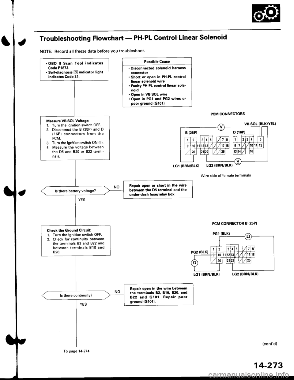
Troubleshooting Flowchart - PH-PL Control Linear Solenoid
NOTE: Record all freeze data before you troubleshoot.
Possibls c.use
. Oisconn6dod solenoid harness
conn6ctol. Short or ooen in PH-PL controllinear solenoid wire. F.ulty PH-PL cont.ol linear sole-noid. ODen in VB SOL wire. Op€n in PGl and PG2 wires orpoor ground lG101l
PCM CONNECTORS
Wire side of female terminals
LGT IBRN/BLKILG2 IBRN/BLK)
(cont'd)
B (25P1 D {16P}
. OBD ll Scan Tool indicates
Codo P1873.. sslt-disgnosis E indicltor lightindicates Code 31.
Mo.surevB SOL Vohagg:1. Turn the ignition switch OFF.
2. Disconnect the 8 (25P) and D(16P) connectors from the
PCM,3. Turn tho ignition switch ON (ll),
4. Measure the voltage between
the D5 and 820 or 822 termi-nals,
Ropair open or shod in the wiJe
bstwaon tho D5 terminal and the
under-dalh tuso/relay box.
Check the Ground Circuh:1. Turn the ignition switch OFF2. Check tor continuity betweenthe terminals 82 and 822 andbetween terminals 810 and820.
Fepair open in tho wiro b€tw€entho torminds 82, 810, 820, and
822 and G101. Repair Poorground (G1011.
(BRN/BLX)
Fo page 14-274
PCM CONNECTOR B (25P|
14-273
Page 951 of 2189
Electrical Troubleshooting ('99 - 00 Models)
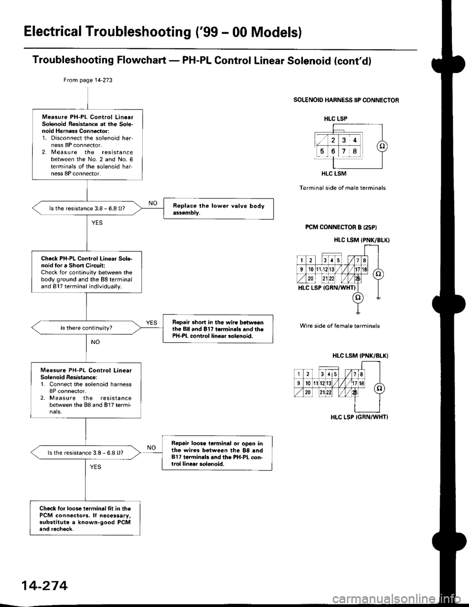
Troubleshooting Flowchart - PH-PL Gontrol Linear Solenoid (cont'd)
From page l4-273
SOLENOID HARNESS 8P CONNECTOR
Terminal side of male terminals
PCM CONNECTOR B (25PI
Wire side of female terminals
Mea3ure PH-PL Control LinearSolenoid Rosistance at lhe Sole-noid Harness Connector:1. Disconnect the solenoid har-ness 8P connector.2. Measu re the resistancebetween the No. 2 and No. 6terminals oI the solenoid harness 8P connector.
ls the resistance 3.8 - 6.8 O?
Check PH-PL Control Linear Sole-noid lor a Short Circuit:Check for continuity between thebody ground and the 88 terminaland 817 terminal individually.
Rep.i. 3hort in the wiro bsh^,eenlhc 88 and 817 terminals and thePH-PL cont.ol linear solenoid.
Measure PH-PL Control LinearSolenoid Resistance:1. Connect the solenoid harness8P connector,2. Measure the resistancebetween the 88 and 817 termi-nals.
Repair loose te.minal or open inthe wires between the 88 rnd817 te.minlb .nd the PH-PL con-trol linear solenoid.
ls the resistance 3.8-6.8 O?
Check lor loose ierminal fit in thePCM connectoTa. lf necessary,substitute a known-good PCM.nd recheck.
HLC LSP
HLC LSM
HLC I.SM (PNK/BLK)
HLC LSM {PNK/BLKI
-j-i8lisli.((
35/11
Il0A/'.n20
HLC LSP IGRN/WHT}
14-274
Page 952 of 2189
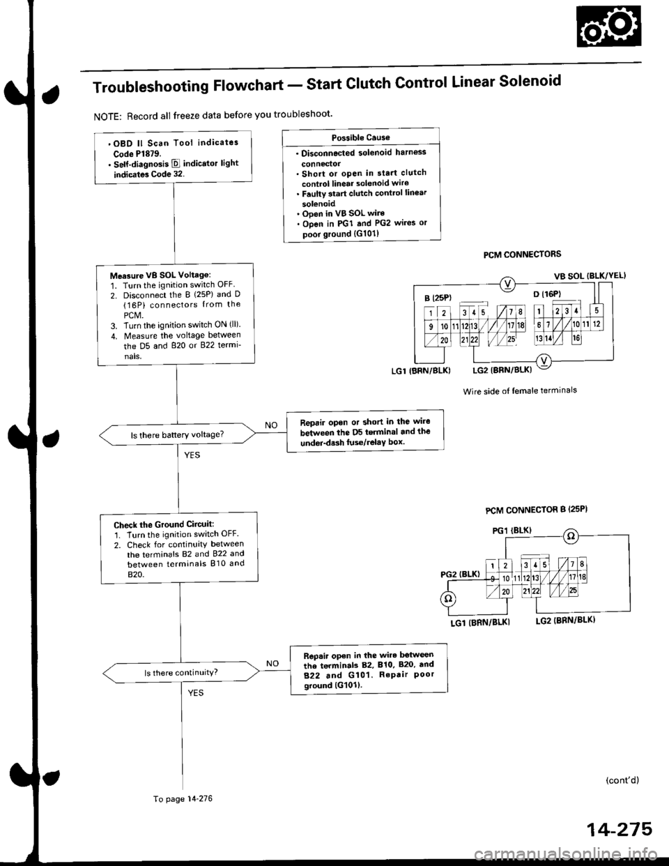
Troubleshooting Flowchart - Start
NOTE: Record all freeze data before you troubleshoot'
Clutch Control Linear Solenoid
PCM CONNECTORS
Wire side of lemale terminals
LGl (BRN/BLKI
(cont'd)
14-215
Po$ible Cause
. Disconnected solenoid harness
connedol. Short or open in sta.t clutch
control linear solenoid wiro. Faulty 3tart clutch conttol lin€ar
solenoid' Ooen in VB SOL wire. Open in PGI and PG2 wires or
poor ground {G101)
B l25P) -- o l16P)
'OBD ll Scan Tool indicates
Code Pl879.. self-diagnosis E indicstor light
indicates Code 32.
Measure VB SOL Voltag6:
1. Turn the ignition switch OFF
2. Disconnect the B {25P) and D(16P) connectors {rom the
PCM.3. Turn the ignition switch ON (ll).
4. Measure the voltage between
the D5 and 820 or 822 termi-
nals,
Reprir opon or short in the wire
between the D5 terminal and the
undei-d.sh luse/relaY box.ls there battery voltage?
Check the Ground Ciicuit:'1. Turn the ignition switch OFF.
2. Check for continuity between
the terminafs 82 and 922 and
between terminals 810 and
820.
Rep.ir open in the wire betwesn
the terminab 82, 810, 820. tnd
822 and G101. RePair Poorground lG101l.
ls there continuity?
LGl IBRN/BLK)
To page 14-276
PCM CONNECTOR B {25PI
Page 953 of 2189

Electrical Troubleshooting ('gg - 00 Modelsl
Troubleshooting Flowchart - start clutch control Linear solenoid (cont,d)
Frcm page 14.275
SOLENOID HARNESS 8P CONNECTOR
T6rminal side of male terminals
Wire side of f6male terminals
SC LSM(PNK/BLU)
Measurs Start Clutch ControlLinear Solenoid R€aistance at thsSolenoid Harne€s Connector:1. Disconnect the solenoid har-ness 8P connector.2, M easu re the resistancebetween the No. 4 and No. Iterminals of the solenoid har-ness 8P connector,
ls the resistance 3.8- 6.8 0?
Check Start Clutch Control Line.rSolenoid tor a Short Circuit:Check for continuity between thobody ground and the 818 termi-nal and B2Sterminal individually.
R€p.ir short in th. wire bctw.onth6 818 and 825 termin.lr rndthe 3hift cont ol linc.r solonoid.
Measure Start Clutch ControlLinear Solenoid R6ist.nco:1. Connect the solenoid harness8P conn€clor.2. Measure the resistancebetlveen the 818 and 825 ter,mtnats,
Raprir looa. t€.minal or opan intha wirars lratwe.n the B18 and825 terminal3 and tha st!rtclutch control linoar 3olanoid,
ls the resistance 3.8-6.8 O?
Check to. loose tarminal fit in thoPCM connactors. It necessary,substitute a known-good PCMand recheck.
SC LSP
SC LSM
14-276
Page 954 of 2189
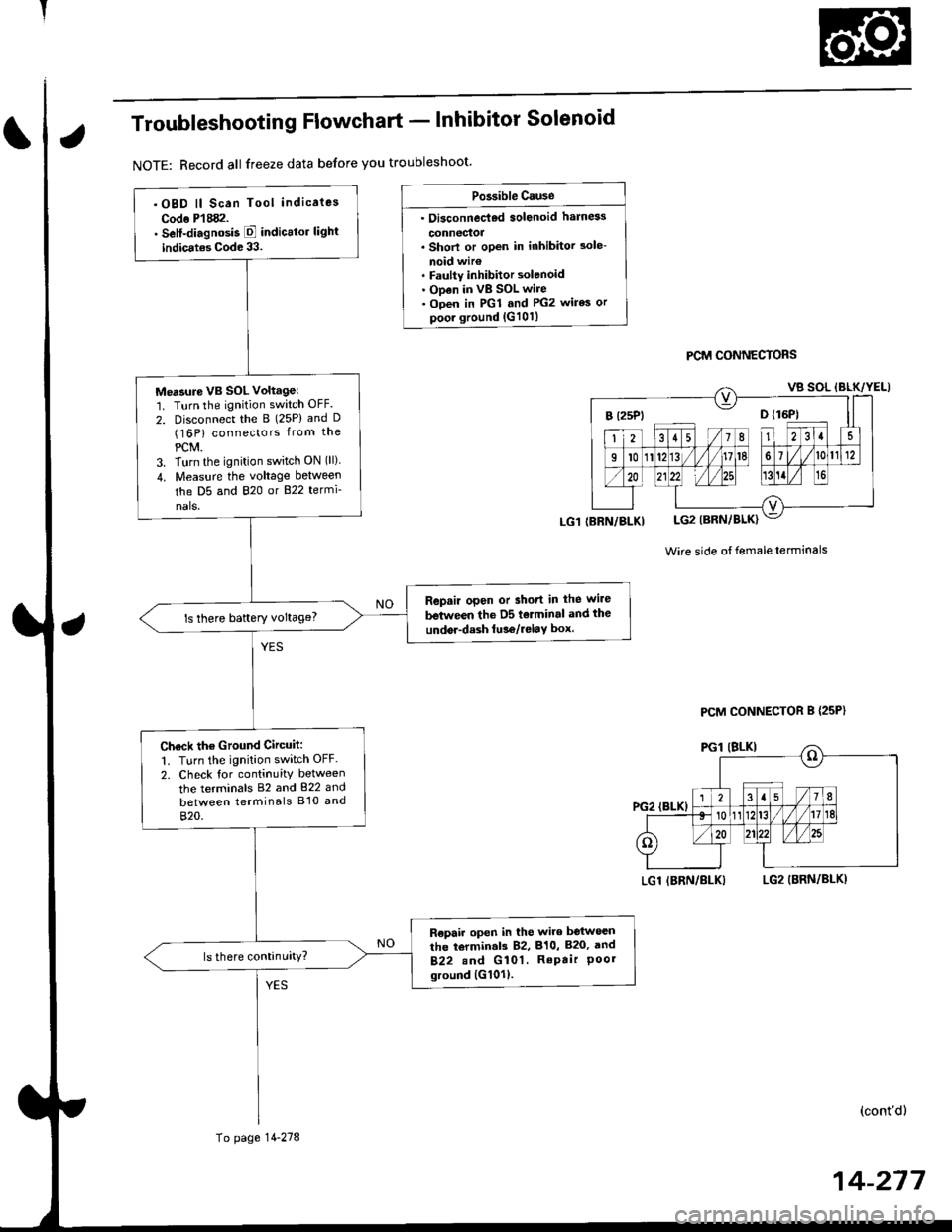
Troubleshooting Flowchart - lnhibitor Solenoid
NOTE: Record all freeze data before you troubleshoot'
Po3sible Cause
. Oi3connec'ted solenoid harn6s
connectoa. Shorl or open in inhibitor 3ole-
noid wir€. Faulty inhibitor solenoid. ODen in vB SOL wire. Open in PGl and PG2 wires or
poor ground {G101}
PCM CONNECTORS
Wire side ot female terminals
LGl IBRN/BLKILG2 (BRN/BLKI
(cont'd)
14-217
.OBD ll Scan Tool indicaies
Codo P'l882.. Self-diagnosis E indicttor light
indic.tes Code 33.
Me'sure VB SOL voltagel'1. Turn the ignition switch OFF.
2. Disconnect the B (25P) and D(16P) connectors from the
PCM.3. Turn the ignition switch ON (ll)
4. Measu.e the voltage between
the D5 and 820 or B22 termi-
nals.
Repair open or short in the wire
between the D5 tolminal and the
undor-dash lu36/relay box.ls there baftery voltage?
Ch€ck the Ground Circuit:
1. Turn the ignition switch OFF.
2. Check tor continuity between
the terminals 82 and 822 and
between terminals B'10 and
820.
R€pair open in the wire between
the torminal3 82, 810, B20, and
B22.nd G 101. RePair Poorground {G101).
(BRN/BLKI
To page 14-278
PCM CONNECTOR B {25P}