1999 HONDA CIVIC troubleshooting
[x] Cancel search: troubleshootingPage 926 of 2189

Troubleshooting Flowchart - Manifold
NOTE: Record all freeze data before you troubleshoot
Absolute Pressure {MAPI Sensor
TCM CONNECTORS
Wire side of female terminals
PG.iblo Cau3€
. Dkconnoctod manilold .bsoluto
ore33urc IMAP) sensor connoc'
lor. Short or opcn in MAP s.nsor
MAP sen3or
. OBD ll Scan Tool indicates Code
P1793,. self-diagno3b E indicato. light
indicat€s Code 12.
Chock tor Another Cod€ or MIL
Blinking:1. Turn the ignition switch ON (ll).
2. Check whether the OBD ll scan
tool indicates another code or
the Mal{unction Indicator LamP(MlL) blinks (sse section 11).
Does the OBD llscan tool indicate
another code or isthe lVlL blink-
in9?
Measure VREF voltage:
1. Turn the ignition switch OFF.
2. Disconnect the A (26P) and B
(22P) connectors trom the
TCM.3. Turn the ignition switch ON (ll).
4, Measure the voltage between
the B2O and A13 or A26 termr
nals.
R€pair opon or 3hort in the wire
botwoan the 820 t€.minal and
the EcM.lsthere aPprox.5 V?
Msasure MAP IPB) volt.ge:
Measure the voltage betlveen the
82 and A13 or 426 terminals.
Repair opon ot shorl in the wiro
betwesn the 82 torminal end th€
MAP sensol.ls there approx. 3 V?
Check for loo3e TCM conn€stors.
lf nec*sarY, sub3titute a known'
good TCM and rechock.
WHT/RED
14-249
Page 927 of 2189

Electrical Troubleshooting (,96 - 9g Modelsl
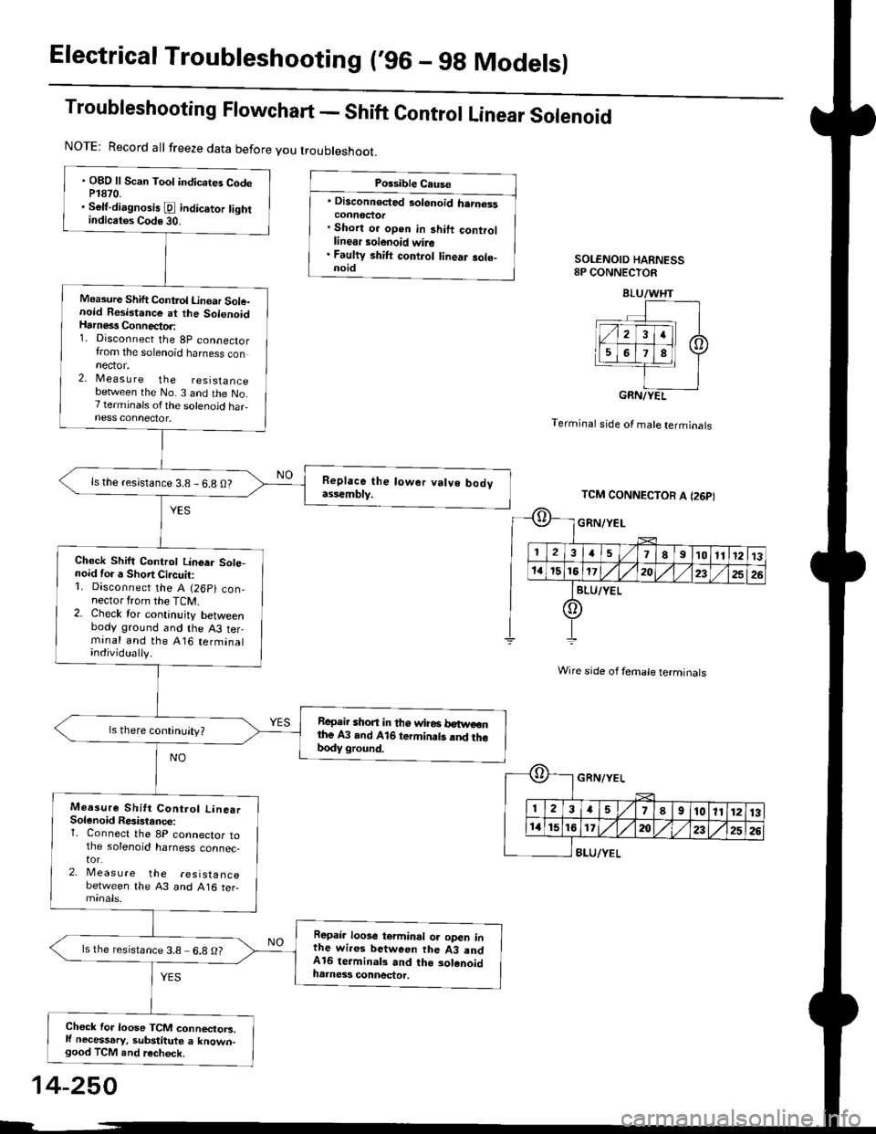
Troubleshooting Flowchart - Shift Control Linear Solenoid
Possible Cause
' Disconnected 3olenoid h.rn€isconnoctor. Short or open in 3hift controllinear solenoid wire. Faulty shift control linear sole-noidSOLENOID HARNESS8P CONNECTOR
Terminal stde of male terminals
Wire side of female terminals
8LU/YEL
NOTE: Record all freeze data before you troubleshoot.
. OBD ll Scan Toot indicates CodeP1870.. Selt-dirgnosis [d indic.tor tightindicatos Code 30.
Measure Shift Control Linoar Sole-noid Resistance at the SolenoidHarness Connector:1. Disconnect the 8p connectorfrom the solenoid harness connector.2, Measu re the resistancebetlveen the No. 3 and the No.7 terminals ofthe solenoid haFness connector.
ls the resistance 3.8 - 6.8 O?
Check Shift Controt Linear Sote-noid for a Short Circuit:1. Disconnect the A (26p) con,nector from the TCM.2. Check for continuity betweenbody ground and the A3 terminal and the A16 terminalindividually.
Repair shon in tho wire6 betweonthe A3 and A16 termin.ts lnd thobody ground.
Measure Shitt Control Line.rSolenoid Resistance:1. Connect the 8P connector tothe solenoid harness connec,tor.2, Meas u re the resistancebetween the 43 and A16 ter-
Repair loose terminal oa open inthe wires between the 43 andA16 terminal3 and the solenoidharness connector.
ls the resistance 3.8 6.8 O?
Chock for loose TCM connectorc.ll necessary, substitute a known-good TCM and recheck.
BLU/WHT
GRN/YEL
TCM CONNECTOR A I26PI
GRN/YEL
ll 12l:
IriGlx
1578910111213
172t)232526
14-250
Page 929 of 2189

Electrical Troubleshooting ('96 - gg Modelsl
Troubleshooting Flowchart - start clutch control Linear solenoid
NOTE: Record all freeze data before you t.oubleshoot.
Po$iblo C.u.o
' Di3aonnoctod solanoid harncatconnactol. Short or opon in start clutchcontrol linoar tolanoid wira. Faulty ttart clutch control lino.rsolanoid
SOLENOID HARNESS8P CONNECTOR
Terminal side of male terminals
Wire side of female terminals
. OBO ll Scan Tool indicatG CodeP1879.. Self-dilgno.is E indicator lightindiclt$ Code 32.
Me.suro Sta.t Clutch ControlLinear Solenoid Rosirtrnco st th.Solenoid Hrrn6rs Connecto.:1. Disconnect the 8P connectorfrom the solenoid harness con-nector.2, Measure the resistancebetween the No. 4 and the No.8 terminals otthe solenoid har-ness connectot.
ls the resistance 3.8 - 6.8 0?
Chock Start Clutch Control Lin-oar Solenoid tor a Short Circuit:1. Disconnect the A (26p) con,nector from the TcM.2. Check lor continuity betweenbody ground and the A1 ter-rninal and lhe Al il terminalindividually.
Raprir 3hort in tha wira3b.ftvcen tho A1 .nd Atil t .mi.n.l. .nd thr body ground.
Measure Stan Clutch Cont.olLineer Solenoid F6aist.ncei1. Connect the 8P connector tothe solenoid harness connec-tor.2. Meas u re the resistancebetween the 41 and Al4 ter-minals,
Rcplir loose tcrminal or oDcn inthG wiras b.tween the Al rndAla torminal3 rnd tha 3olanoidhamaas connactor.
ls the resistance 3.8- 6.8 O?
Check for loose TCM connecto.s.lf necessary, substitute a known-good TCM and iecheck.
YEL
PNK/BLU
TCM CONNECTOR A I26P}
-{r-
E
PNK/BLU
23a51I910ll1213
a15t61'20a252G
YEL
14-252
Page 930 of 2189

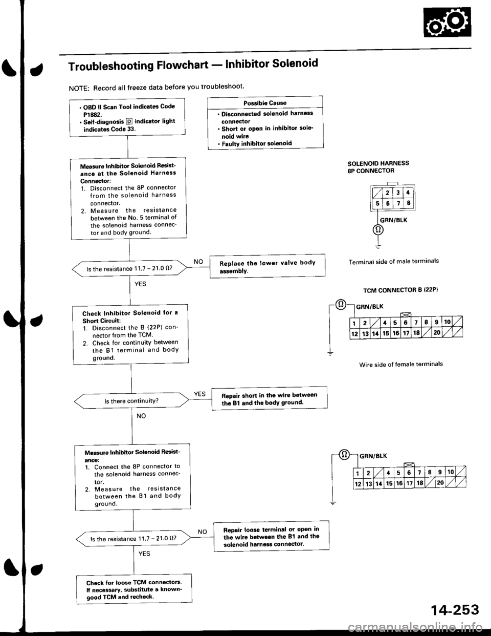
Troubleshooting Flowchart - Inhibitor Solenoid
NOTE: Record all treeze data betore you troubleshoot
Po$ibls Cause
. Dbconnected solenoid hatness
connedor' Short or opon in inhibitor sole'
noid wire. Faultv inhibitor solenoid
SOLENOID HARNESS8P CONNECTOR
Terminal side of male terminals
. OBD ll Scan Tool indic.td Code
P1882.. Selt-di.gnGis E indicator lighl
indic.tos Code 33.
Mea3ure Inhibhor Solenoid Resid-
ance at the sol€noid Harness
Connector:1. Disconnect the 8P connector
from the solenoid harness
connector.2. Measure the reslstance
betlveen the No 5 terminal of
the solenoid harness connec-
tor and body ground.
ls the resistance 11.7 - 21 0 0?
Check Inhibitor Solenoid lor a
Short Circuii:1. Disconnect the B (22P) con-
nector from the TCM.
2. Check for continuity between
the B1 terminal and bodygro!no.
Repair rhort in the wire ltetwegn
the 81 dnd the bodY ground.
Mea$rr€ Inhibitor Solenoid ResBt'
anoe:1. Connect the 8P connector to
the solenoid harness connec_
IOr.2. Measure the resistance
between the Bl and bodyground.
Reoair loose terminal or open in
the wire betwean the 81 and the
solenoid hame3s connector'ls the resistance 11.7 - 21.0 O?
Ch6ck for loose TCM connectors.
ll necessary, substhule a known_good TCM and techeck.
Wire side of female terminals
14-253
Page 931 of 2189

Electrical Troubleshooting {'96 - 9g Models)
Troubleshooting Flowchart - Drive pulley Speed Sensor
' OBD ll Scan Tool indicates CodeP1885.. Self-diagnosis E indicator tightindicates Code 34.
NOTE: Record all freeze data before you troubleshoot,
Check the drive pulley speed sen,sor installation.
ls the drive pulley speed sen-sor installed properly?
M6a3ure Drive Pulley Sp€ed S€n-sor Resistance ai the Seosor Con-nectot:1. Disconnect the 2P connectorfrom the drive pulley speedsensor connector.2. Measure the resistance of thedrive pulley speed sensor.
ls the resistance 350 - 600 O?
Check Orive Pulley Speed Sen-sor tor a Short Circuit:1. Disconnect the B (22P)connec-tortrom the TCM.2. Check for continuity betveenbody ground and the 810 ter-minal and 817 terminal individually.
Rspair shon in the wi.es botwoenthe Bl0 and 817 te.minals andthe driva pulloy 3peod 3eniol.
Measure Drive Pulley Sp€€d Sen-sor Re3istance:1. Connect the drive pulley speedsensor 2P connector.2, Meas u re the resistancebetween the 810 and 817 ter-mtnals.
Repair loos6 t.rmin.l or open inth. wiros botweon tho Bl0 and817 torminals and thg driva pul-ley sp€gd sensor.
ls the resistance 350 - 600 O?
Check tor looso TCM connoctor.ll necessary, substituto a known-good TCM and recheck.
Po$ible Cause
. Oisconn€cted drive pulley speedsensor connector. Shon or op€n in drive pulleyspged sonsor wire. Faulty drive pulley spoed s.n-sot
ORIVE PULLEY SPEEDSENSOR 2P CONNECTOR
lT_ T---_l
1 | 2 tlt|�]--+i-rr
l9tl
L_t
side oI male terminals
TCM CONNECTOR 8 I22PI
REO/BLU
Terminal
Wire side of female terminals
REO/8LU
J(l
24568910v1213t41516171820
GRN
o
1215iliI;W1M
1213111516tdil)lil/l
GRN
14-254
b
Page 932 of 2189

Troubleshooting Flowchart - Driven Pulley Speed Sensor
NOTE: Record all freeze data before you troubleshoot'
Po3sible Cause
. Disconnected dtiven PulleYso6ed sensor connector. Short or open in driven PulleYapeed sen3or wire. Faulty driven PulloY sPeod 3en-
DRIVEN PULLEY SPEEOSENSOR 2P CONNECTOR
l-_r-|1 2l
:-
t9tt
L_.1
Terminal side of male
TCM CONNECTOR I l22p)
WHT
termrnals
. OBD ll Scan Tool indicates Code
P1886.. Sell-diagnosis E indicator light
indicates Code 35.
ls the driven Pulley speed sen-
sor installed proPerlY?
M€asure Driven Pulley SP€ed Sen_
sor Resbt nce at the Sensor Con-
neclof:1. Disconnect the 2P connector
from the driven PUlley speed
sensor connectol.2. Measure the resistance ot the
driven pulley speed sensor.
ls the resistance 350 600 0?
Check Driven Pulley Speed Sen-
sor {or a Short Circuit:1. Disconnect the B (22P) connec_
tor from the TCM.2. Check for continuity between
body ground and the BB ter
minal and 89 terminal individ'
Repair sho.t in the wiles between
lhe 88 and Bg lerminals tnd the
driven pulleY 3Peed 3€nsor.
Measure Driven Pulley SPeed S€n-
sor Reistance:1. Connect the driven PulleYspeed sensor 2P connector'
2. M easu re the resistance
between the 88 and Bg terml_
nals.
Repair loos€ terminal or oPen in
the wires between the Bg and Bg
torminals and the dtiven Pulley3D6eO S6n50a,
ls the resistance 350 - 600 O?
Check lor loose TCM connector.
lf necessary, substitute a known_good TCM and rechack.
^\, REO/BLUo
12a68910
12131a15'16'171820
Wire side oI female terminals
RED/BLU]
o
WHT
1216810
12131a1516171820
14-255
Page 933 of 2189

Electrical Troubleshooting ('96 - 98 Modelsl
Troubleshooting Flowchart - Secondary Gear Shaft Speed Sensor
Po$ible Cause
. Disconnected secondary gealshaft speod sen3or connectol. Short ol open in s€condary gearshaft spe€d sen3or wiro. Faulty secondary gear shattspeed s€nsor
SECONDARY GEAR SHAFT SPEEDSENSOR 2P CONNECIOR
llll;ll
T_T
l@
tl
LJ
side of male terminalsTerminal
TCM CONNECTOR B {22P}
Wire side of female termanals
14-256
NOTE: Record all freeze data before you troubleshoot.
. OBD ll Scan Tool indicates CodeP1888.. Selt-diagnosis Iq indicator lightindicates Code 36.
Check the secondary gear shaftspeed sensor installation.
ls the secondary gear shaft speedsensor installed properly?
Measure Secondary Gear SheftSpeod Sensor R8istance at theSensor Connector:1. Disconnect the 2P connectorfrom the secondary gear shaftspeed sensor connector.2. Measure the resistance ol thesecondary gear shalt speed
ls the resistance 350 - 600 0?
Check Counterchaft Speed Son-sor for a Short Circuit:1. Disconnect the B 122P) connectorfrom the TCM.2. Check for continuity betweenbody ground and the 815 terminal and 816 terminal individually.
Repair short in the wir€6 bctuveenth. 815 and 816 torminrls.ndthe s€condary ge.r shaft speodls there continuity?
Measu.e Secondary Gear ShattSpeed Sensor Resistance:1. Connect the secondary gearshaft speed sensor 2P connec-
2. Meas u re the resistancebetween the 815 and 816 te.mrnals.
Reprir loose terminal or opcn inthe wires between the 815 and8'16 terminals and the secondaryg€ar shaft sp€ed s€nsor,
ls the resistance 350 600 O?
Check lor loose TCM connector.lf n€cessary, substitute a known-good TCM and recheck.
I2156910
12131a1516171820
WHT/RED T - ORN/BLU
D (o.
1a5678I10
1213141515171820
WHT/REI
A
I
ORN/BLU
L
Page 934 of 2189

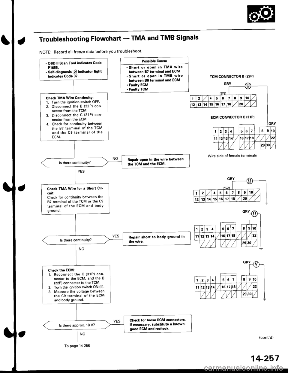
Troubleshooting Flowchart - TMA and TMB Signals
NOTE: Record all freeze data before you troubleshoot'
Possible Cause
. Shorl or op.n in TMA wi.o
botwo6n 87 terminal and ECM. Short or open in TMB wiro
bdtwoon BG to.min.l .nd ECM. F.ulty ECM. Faulty TCM
TCM CONNECTOR B (22P)
GRY
Wire side oI temale terminals
o
I2a58910
1213111516171820
GRY
ECM CONNECTOR C 13lPI
123a56l89r0
1112t3la1618//
29130 /
::)
I2a568910
12t3141516171820
. OBD ll Scsn Tool indicate3 Codo
P1655.. Self-diagnosb E indicator light
indicales Cod6 37.
Check TMA Wire Continuity:1. Turn the ignition switch OFF.
2- Disconnect the I (22P) con-
nector lrom the TCM
3. Disconnect the c (31P) con'
nector from the ECM
4. Check for continuity between
the 87 terminal of the TCM
and the Cg terminal oI the
ECM,
Ropail open in the wire betwcen
the TCM and the ECM.
Check TMA Wir€ for a Short Cir-
cuit:Check for continuity between the
87 terminal of the TCM or the Cg
terminal ol the ECM and bodyground.
check rhe EcM:1. Reconnect the C (31P) con'
nector to lhe ECM, and the B(22P) connector to the TCM
2. Turn the ignition switch ON (ll).
3. Measure the voltage between
the C9 terminal oI the ECM
and body ground.
Chock tor loose ECM connectors.
lf nscossary, subdituta a known'good ECM .nd lecheck.ls there approx. 10 V?
To page 14 258
(cont'd)
14-257