Page 1031 of 2189

t
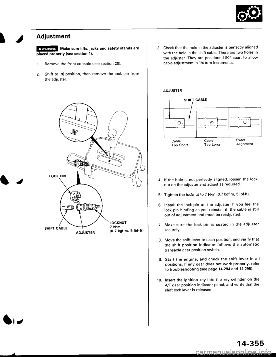
Adjustment
!@ Make sure lifts, jacks and safety stands are
placed properly (see section 1).
l. Remove the front console (see section 20).
2. Shift to I posirion, then remove the lock pin from
the adjuster.
SHIFT CAELE
l,
,l
{0.7 kgf.m, 5lbf'ltl
3. Check that the hole in the adiuster is perfectly aligned
with the hole in the shift cable. There are two holes in
the adjuster. They are positioned 90" apart to allow
cable adjustment in 1/4 turn increments.
lf the hole is not perfectly aligned, loosen the lock-
nut on the adjuster and adjust as required.
Tighten rhe locknut to 7 N.m (0.7 kgim,5 lbf'ft).
Install the lock pin on the adjuster' lf you feel the
lock pin binding as you reinstall it. the cable is still
out of adjustment and must be readjusted
Make sure the lock pin is seated in the adiuster
securery.
lMove the shift lever to each position, and verify that
the shift position indicator follows the automatlc
transaxle gear position switch.
Start the engine, and check the shift lever in all
positions. lf any gear does not work properly, refer
to troubleshooting (see page 14-294 and 14-295).
Insert the ignition key into the key cylinder on the
Aff gear position indicator panel, and verify that the
shift lock lever is released.
7.
10.
14-355
Page 1033 of 2189
Shift Indicator PanelATF Gooler/Hoses
Adjustment
1.Check that the index mark on the indicator aligns
with the E mark on the shift indicator panel when
the transmission is in NEUTRAL.
lf not aligned, remove the front console {see section
20).
Remove the shift indicator panel mounting
and adjust by moving the panel.
NOTE: Whenever the shift indicator panel is removed,
reinstallthe Danel as described above.
It,
14-357
lnstallation
1. Installthe ATF cooler, ATF cooler line assembly and
the ATF cooler hoses.
6x1.0mm11 N.m ('l 1 kgf.m,8.0lbl'ftlATF COOLER LINE ASSEMBLY
ATF COOLER HOSE
RADIATOR
6x1.0mm9.8 N.m 11.0 kgf'm, 7 8 lbf'ft)
ATF COOLER
Connect the ATF cooler
lines and ATF cooler. and
as shown.
hoses to the ATF cooler
secure them with the clips
1l lTf{il.T
6-8mm10.2 - 0.3 in)
33-35mm11.3 - 1.4 inl
2-1mm10.1 - 0.2 in)
2-ilmm{0.1 - 0.2 in)
ATF COOI..ER HOSES
Page 1036 of 2189
Driveshafts
Inspection
Driveshaft Boot
Check the boots on the driveshaft for cracks, damage,
leaking grease and loose boot bands. lf any damage is
found, replace the boot and boot bands,
Loose Splines
Turn the driveshaft by hand and make sure the splines
and joint are not excessively loose. lf any damage is
found, replace the inboard joint.
Twisied or Cracked
Make sure the driveshaft is not twisted or cracked.
Reolace it if necessarv.
DRIVESHAFT
BOOT BANDS
1.
Removal
Loosen the wheel nuts slightly.
Raise the front of the vehicle, and support it with
safety stands in the proper locations (see section 'l).
Remove the wheel nuts and front wheels.
Drain the transmission fluid (see section 13 or 14).
Raise the locking tab on the spindle nut, then
remove the nut.
Remove the selJ-locking nut and flange bolts.
FLANGE BOLT10 x 1.25 mm
(cont'd)
16-3
1.
Page 1037 of 2189

Driveshafts
Removal (cont'd)
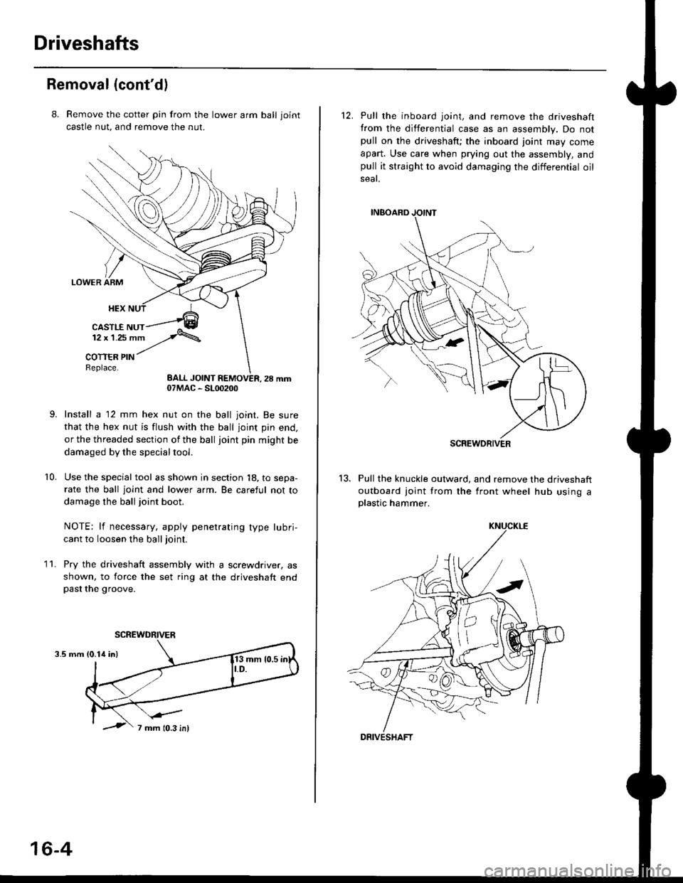
8. Remove the cotter pin from the lawer arm ball joint
castle nut. and remove the nut.
Install a 12 mm hex nut on the ball joint. Be sure
that the hex nut is flush with the ball joint pin end,
or the threaded section of the ball joint pin might be
damaged by the special tool.
Use the special tool as shown in section 18, to sepa-
rate the ball joint and lower arm. Be careful not to
damage the ball joint boot.
NOTE: lf necessary, apply penetrating type lubri,
cant to loosen the ball joint.
Pry the driveshaft assembly with a screwdriver, as
shown, to force the set ring at the driveshaft endpast the groove.
10.
11.
3.5 mm
07MAC - SL00200
SCREWDRIVER
16-4
12. Pull the inboard joint, and remove the driveshaft
from the differential case as an assembly. Do notpull on the driveshaft; the inboard joint may come
apart. Use care when prying out the assembly, andpull it straight to avoid damaging the differential oil
seat.
13. Pull the knuckle outward, and remove the driveshaft
outboard joint from the front wheel hub using aplastic hammer.
SCREWDRIVER
DRIVESHAFT
Page 1038 of 2189
t
Disassembly
lnboard Joint Side:
1. Carefully clamp the driveshaft in a vise with soft
jaws, then remove the set ring from the inboard
joint.
2. Remove the boot bands. Take care not to damage
the boot.
. lf the boot band is a locking tab type, pry up the
locking tabs with a screwdriver, and raise the
end of the band.
. It the boot band is a welded type, cut the boot
ba nd.
. lf the boot band is a crimping type, pry up the
end of the band with a screwdraver.
. lf the boot band is a double loop type, lift up the
band bend.
Locking Tab Typs
Welded Type
J
Replace.
l,
Crimping Type
Double Loop Type
Mark each roller and inboard joint to identify the
locations of rollers and grooves in the inboard joint.
Then remove the inboard joint on the shop towel.
Be careful not to drop the rollers when separating
them from the inboard ioint.
INBOARD JOINTCheck splines for wear or damage,Check inside bore for wear.Inspect for cracks.
(cont'd)
16-5
Page 1039 of 2189

Driveshafts
Disassembly (cont'dl
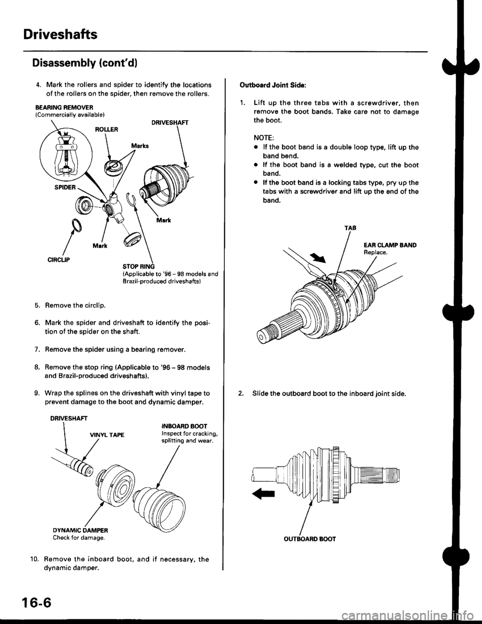
4. Mark the rollers and spider to identify the locations
of the rollers on the sDider, then remove the rollers.
B€ARING REMOVER{Commerciallv available}
STOP RING(Applicable to '96 - 98 modols andErazil-produced driveshafts)
Remove the circlip.
Mark the spider and driveshaft to identify the posi-
tion ot the spider on the shaft.
Remove the spider using a bearing remover.
Remove the stop ring (Applicable to '96 - 98 models
and Brazil-produced driveshafts).
Wrap the splines on the drivsshaft with vinyl tape to
prevent damage to the boot and dynamic damper.
DRIVESHAFT
1.
VINYL TAPE
DYNAMIC DAMPERCheck for damage.
Remove the inboard
dynamic damper.
INBOARO AOOTInspect for cracking,splitting and wear.
16-6
boot, and if necessary, the
Outboard Joint Side:
1. Lift up thc three tabs with a screwdriver, then
remove the boot bands, Take care not to damage
the boot.
NOTE:
. lf the boot band is a double loop type, lift up the
band bend.
. lf the boot band is a welded type, cut the boot
band.
. lfthe boot band is a locking tabs type, pry up the
tabs with a scr€wdriv€r and lift uo the snd of the
band.
2. Slide the outboard boot to the inboard ioint side.
TAB
OUTBOABD BOOT
Page 1046 of 2189
l.
11. Set the double loop band onto the boot and dynam-
ic damper with the band end toward the front ot the
vehicle.
LOOP BANO
Pull up the slack in the band bY hand
Mark a position on the band 10 - 14 mm {0 4 - 0 6
in) from the cliP.
DOUBLE
,
1')
13.
CLIP
Ip
14.
15.
Thread the free end of the band through the nose
section of the boot band tool and into the slot on
the winding mandrel.
Place a wrench on the winding mandrel of the boot
band tool, and tighten the band until the mark you
made on the band meets the edge of the clip.
Mark on band.
Lift up the boot band tool to bend the free end
the band 90 degrees, then center-punch the clip'16.
(cont'd)
16-13
(KD-3191 or equivalent)
HAMMER
Page 1050 of 2189
I
13. Fit the boot ends onto the driveshaft and the
outboard joint
Fit the double loop boot bands onto the boot ends'
Pull up the slack in the band by hand'
Mark a position on the band 10 - 14 mm {0 4 - 0 6
in,) from the cliP.
14.
16.
CLIP
lrz
17. Thread the free end of the band through the nose
section of a commercially avaiiable boot band tool
KD-3191 or equivalent and into the slot on the wind-
ing mandrel.
BOOT BAND TOOL
lCommerciallY available)
KD-3191 or equivalent
MANDREL
Place a wrench on the winding mandrel of the boot
band tool, and tighten the band until the marked
spot on the band meets the edge of the clip'
Lift uo the boot band tool to bend the free end of
the band 90" to the clip Center punch the clip, then
fold over the remaining tail onto the clip
Mark spot.
18.
1q
(cont'd)
16-17