Page 997 of 2189
Manual Valve Body
Disassembly/lnspection/Reassembly
NOTE:
. Clean all parts thoroughly in solvent or carburetor cleaner, and dry with compressed air. Elow out all passages.. Coat all parts with CVT Fluid during assembly.
SPRING SEATREVERSE INHIBITORVALVE SPRING
REVERSE INHIBITORVALVE
MANUAL VALVE
MANUAL VALVE BODYInspect for wear, scratchesand sconng,
14-320
Page 1001 of 2189
Forward Glutch
Reassembly
NOTE:
. Clean all parts thoroughly in solvent or carburetor
cleaner, and dry them with compressed air.
. Blow out all passages.
. Lubricate all parts with CW Fluid before reassembly.
1. Inspect the check valve; if it's loose, replace the pis-
ton.
CHECK VALVE
Install new O-rings on the clutch pision.
PISTON
14-324
3. Install the piston in the clutch drum. Apply pressure
and rotate to ensure proper seatang,
NOTE: Lubricate the piston O-ring with CVT Fluid
before installing.
CAUTION: Do not pinch thc O-ring by installing the
pistoo with too much torqo.
CLUTCH DRUM
Install the return spring and spring retainer, and
position the snap ring on the retainer.
CLUTCH DRUM
Page 1003 of 2189
Forward Clutch
Reassembly {cont'd)
9. Install the disc spring.
NOTE: Installthe disc spring in the direction shown.
- "arr"" o"u*
11.
Soak the clutch discs thoroughly in CW Fluid for a
minimum of 30 minutes.
Starting with a clutch plate. alternately install the
clutch plates and discs. Install the clutch end plate
with flat side toward the disc.
NOTE: Before installing the plates and discs, make
sure the inside of the clutch drum is free of dirt or
other toreign matter.
CLUTCH END PLATEInstall in this dir€ction.
10.
DISC SPRING
14-326
12. Installthe snap ring.
13. Verify that the snap ring end gap is correct.
SNAP RING
CLUTCH
Minimum 7.9 mm (0.31 ini
Page 1004 of 2189

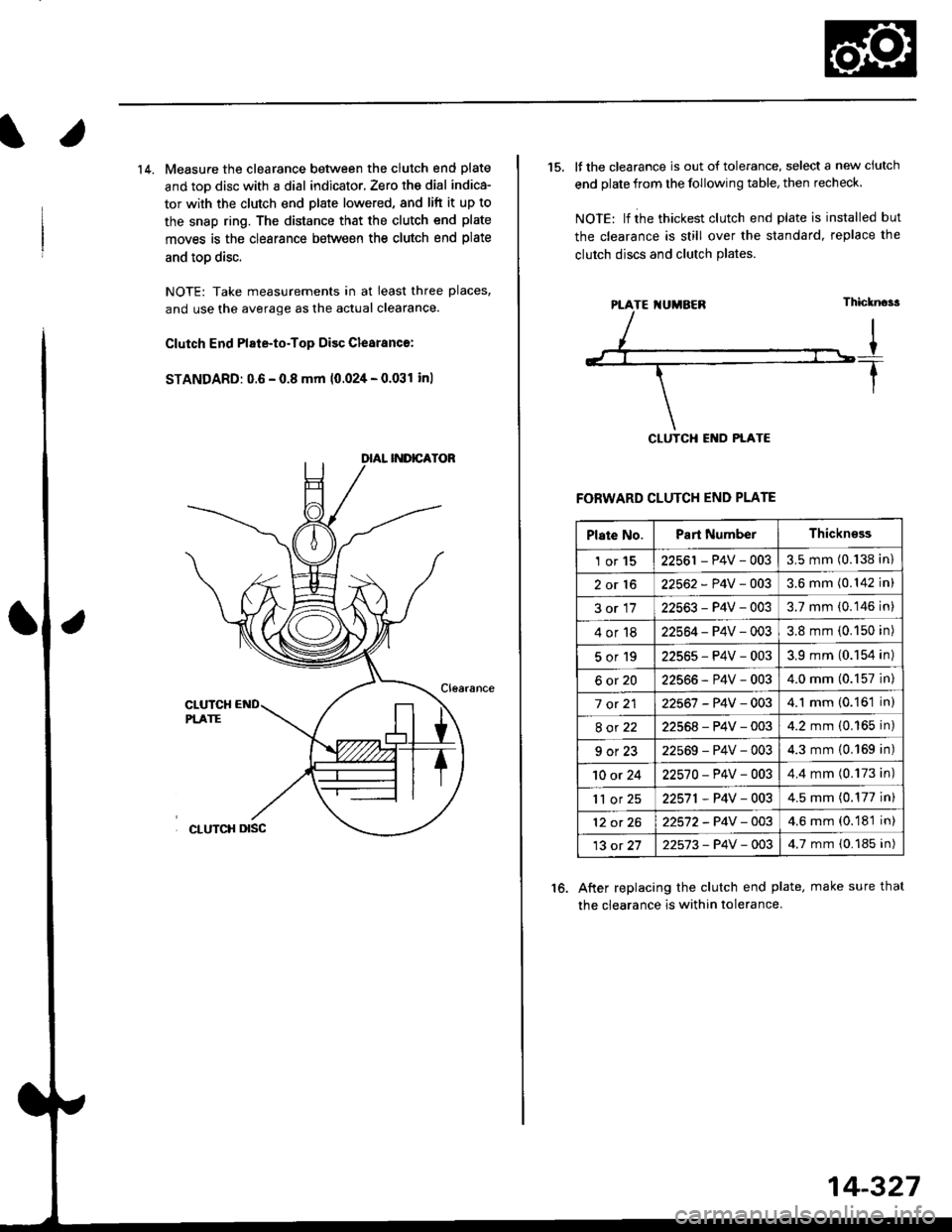
14. Measure the clearance between the clutch end plate
and toD disc with a dial indicator, Zero th€ dial indica-
tor with the clutch end plate lowered, and lift it up to
the snap ring. The distance that the clutch end plate
moves is the clearance between the clutch end plate
and toD disc.
NOTE: Take measurements in at least three places,
and use the average as the actual clearance.
Clutch End Plate-to-Top Disc Clesranc€:
STANDARD: 0.6 - 0.8 mm 10.024 - 0.031 inl
15. It the clearance is out of tolerance, select a new ciutch
end plate from the following table, then recheck.
NOIE: lf ihe thickest clutch end plate is installed but
the clearance is still over the standard, replace the
clutch discs and clutch Plates.
FORWARD CLUTCH END PLATE
After replacing the clutch end plate, make sure thal
the clearance is within tolerance.
16.
PTATE I{UMBEN
Plate No.Part NumberThickn€ss
1or1522561 - P4V - 0033.5 mm (0.138 in)
2or1622562 - P4V -OO33.6 mm (0.142 in)
3or1722563-P4V-0033.7 mm (0.146 in)
4or1822564 - P4V - 0033.8 mm (0.150 in)
5or192256s-P4V-0033.9 mm (0.154 in)
6ot2022566-P4V-0034.0 mm (0.157 in)
7 ot 2122567 -P4V -0034.1 mm (0.161 in)
8ot2222568-P4V-0034.2 mm (0.165 in)
9ot2322569-P4V-0034.3 mm {0.169 in)
10 or 2422570-P4V -OO34.4 mm (0.173 in)
'll or 2522571,P4V-0034.5 mm (0.177 in)
12 ot 2622572-P4V-OO34.6 mm (0.181 in)
13 ot 2722573-P4V -OO34.7 mm {0.185 in)
14-327
Page 1005 of 2189

Secondary Gear Shaft
25 x 35 mm Thrust Shim Selection
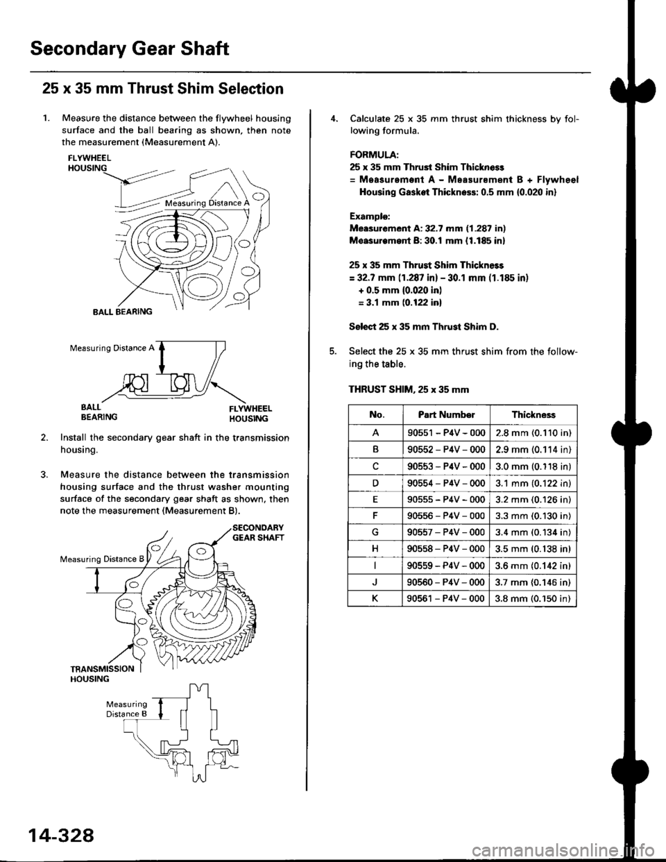
1. Measure the distance between the flywheel housing
surface and the ball bearing as shown, then note
the measurement (Measurement A).
FLYWHEELHOUSING
>dt?'
BALL BEARING
EALL FLYWHEELBEARING HOUSTNG
Install the secondary gear shatt in the transmission
housing.
Measure the distance between the transmission
housing surface and the thrust washer mounting
surface of the secondary gear shaft as shown, then
note the measurement (Measurement B).
O
Measuring Distance A
BALL
14-328
Calculate 25 x 35 mm thrust shim thickness bv fol-
lowing formula.
FORMULA;
25 x 35 mm Thrust Shim Thicknoss
= Measurement A - Measurement B + Flywheel
Housing Gasket Thickness: 0.5 mm {0.020 in}
Example:
Measurement A: 32.7 mm (1.287 in)
Moasurem.nt B: 30.! mm {1.185 in}
25 x 35 mm Thrust Shim Thickness
= 32.7 mm (1.287 in) - 30.1 mm (1.185 in)
+ 0.5 mm {0.020 in)
= 3.1 mm (0.122 inl
Select 25 x 35 mm Thrust Shim D.
Select the 25 x 35 mm thrust shim from the follow-
ing the table.
THRUST SHIM, 25 x 35 mm
No.Part NumberThickne3s
90551 - P4V - 0002.8 mm (0.110 in)
B90552-P4V-0002.9 mm (0.114 in)
c90553-P4V-0003.0 mm (0.118 in)
D90554-P4V-0003.1 mm (0.122 in)
E90555-P4V-0003.2 mm (0.126 in)
90556-P4V-0003.3 mm (0.130 in)
G90557-P4V-0003.4 mm (0.134 in)
H90558-P4V-0003.5 mm (0.138 in)
90559-P4V-0003.6 mm {0.142 in)
90560-P4V-0003.7 mm (0.146 in)
K90561 - P4V - 0003.8 mm (0.'150 in)
Page 1006 of 2189
Differential
l.lllustrated Index
BOLTS10 x 1.0 mm98 N.m 110.0 kgf.m,72 tbl.ltlLeft-hand threads
FII{AL ORIVEN GEAR
BAIT EEANIM;
SET RING. 8() tnmSoloctivo pan
Bacl(lash Inspection
1. Place the differential assembly on V-blocks, and install
both axles.
2. Check the backlash of both pinion gears.
Standard (Newl: 0.05 - 0.15 mm 10.002 - 0.006 in)
PINION GEARS
lf the backlash is out of tolerance, replace the differ-
ential carrier.
14-329
Page 1009 of 2189
Differential
Oil Seal Installation/Side Clearance (cont'dl
3. Installthe flywheel housing, and tighten the bolts.
DOWEL PIN
1 .25 mmN m (3.0 kgt m,22 lbf.ttl8x29
uigE
14-332
4. Measure the clea.ance between the 80 mm set ring
and outer race of the ball bearing in the transmis-
sion housing.
STANDARD: 0 - 0.15 mm (0 - 0.006 in)
lf the clearance is more than the standard, select a
new set ring from the table, and install it.
SET RING, 80 mm
NOTE: lf the clearance measured in steD 4 is stan-
dard, it is not necessary to perform steps 7 and 8.
Remove the flywheel housing.
Replace ttle 2.50 mm (0.098 in) set ring, 80 mm with
the one ot the correct thickness selected in steD 5.
6.
7.
Part NumberThickness
904'�r4-689-000
90415-689-000
90416-689-000
90417-689-000
90418-689-000
90419-PH8-000
2.50 mm (0.098 in)
2.60 mm (0.102 in)
2.70 mm (0.106 in)
2.80 mm (0.110 in)
2.90 mm (0.114 in)
3.00 mm (0.118 in)
Page 1011 of 2189

Transmission Housing Bearings
Driven Pulley Shaft Bearing Replacement
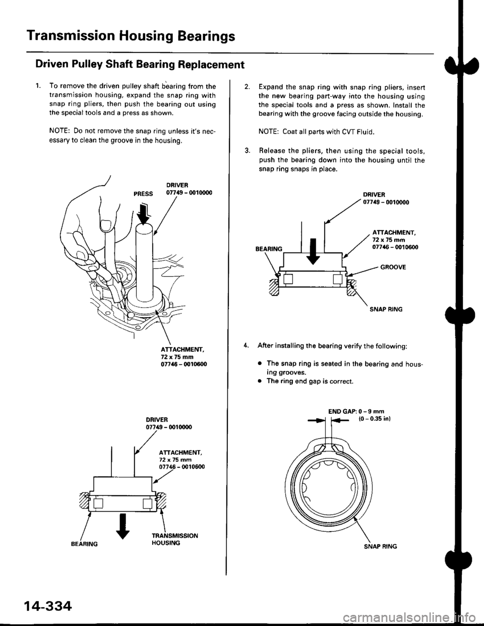
1. To remove the driven pulley shaft b'earing trom the
transmission housing, expand the snap ring with
snap ring pliers, then push the bearing out using
the specialtools and a press as shown.
NOTE: Do not remove the snap ring unless it's nec-
essary to clean the groove in the housing.
07749 - 001(xDo
ATTACHMENT,72x75mm07746 - (x'l05U)
077i() - 001(xrco
14-334
SNAP RING
Expand the snap ring with snap ring pliers, insert
the new bearing part-way into the housing using
the special tools and a press as shown. Install the
bearing with the groove facing outside the housing.
NOTE: Coat all pans with CW Fluid.
Release the pliers, then using the special tools,push the bearing down into the housing until the
snap ring snaps in place.
BEARING
ATTACHMENT,72x75mm07746 - OO1 0600
GROOVE
SNAP RING
After installing the bearing verify the following:
o The snap ring is seated in the bearing and hous-
ing grooves.
. The ring end gap is correct.
END GAP| 0 -9 mm
l0 - 0.35 inl