Page 857 of 2189

17.
18.
19.
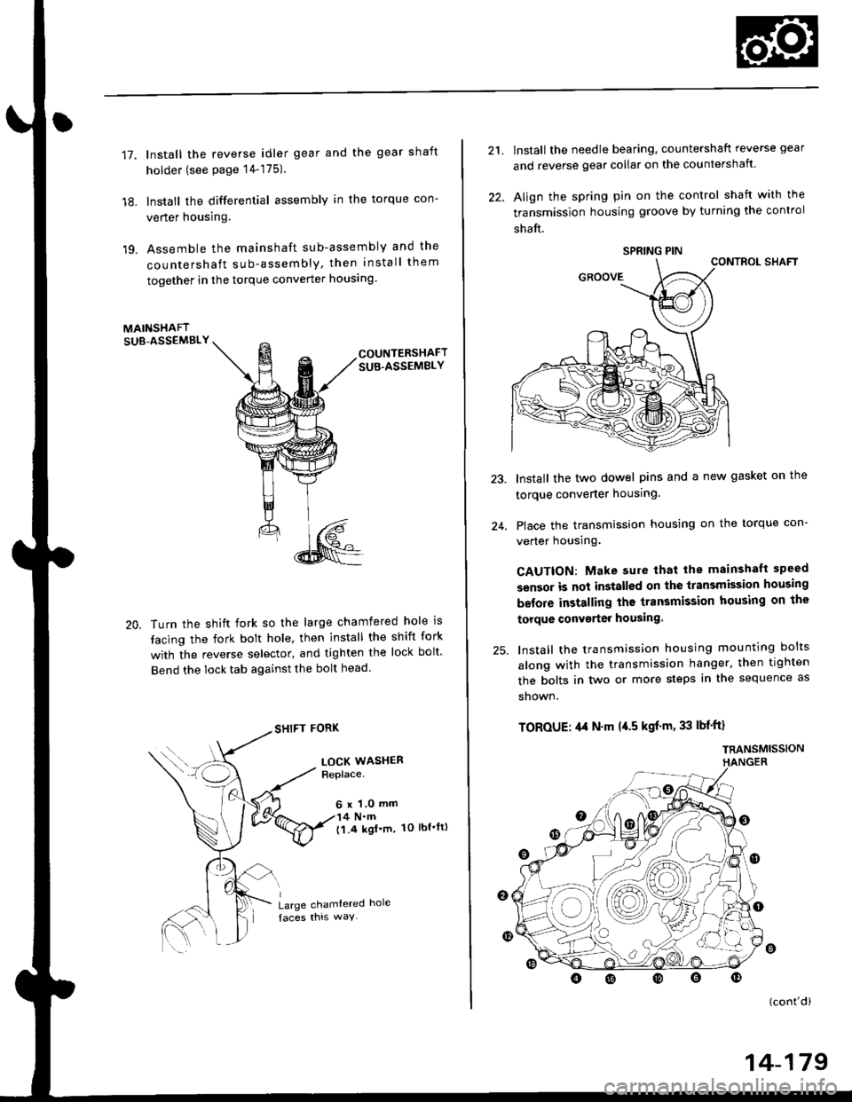
lnstall the reverse idler gear and the gear shaft
holder (see page 14-175).
lnstall the differential assembly in the torque con-
verter housing.
Assemble the mainshaft sub-assembly and the
countershaft sub-assembly, then install them
together in the torque converter houslng
MAINSHAFTSUB-ASSEMBLY
20,
COUNTERSHAFTSUB.ASSEMBLY
Turn the shift fork so the large chamfered hole is
tacing the fork bolt hole, then install the shift fork
with the reverse selector, and tighten the lock bolt'
Bend the lock tab against the bolt head
SHIFT FORK
LOCK WASHERReplace.
6 x 1.0 mm4 N.m('l.4 kgl'm, 1O lbt'ft)
Large chamtered hole
21.
22.
lnstall the needle bearing, countershaft reverse gear
and reverse gear collar on the countershaft.
Align the spring pin on the control shaft with the
transmission housing groove by turning the control
shaft.
CONTROL SHAFT
Install the two dowel pins and a new gasket on the
torque converter housing.
Place the transmission housing on the torque con-
verter housing.
CAUTION: Make sure that lhe mainshaft speed
sensor is not installed on the transmission housing
before installing the transmission housing on the
torque conv€rter housing.
lnstall the transmission housing mounting bolts
along with the transmission hanger, then tighten
the bolts in two or more steps in the sequence as
shown.
TOROUE: ,l,t N'm l{.5 kgf'm, 33 lbf'ft}
TRANSMISSIONHANGER
24.
o
(cont'di
SPRING PIN
14-179
Page 858 of 2189

Transmission
26. Slip the special tool onto the mainshaft as shown,
MAINSHAFT HOLDER07GAB - PF50101
Installthe park lever on the control shaft.
Assemble the one-way clutch and the park gearwith the countershaft lst gear (see page l4-1S5).
Install the countershaft lst gear collar. needle bear_ing, and the countershaft 1st gearlpark gear assembly
Reassembly (cont'dl
on the countershaft.
lSTCLUTCH PARKASSEMBLY GEAR
27.
28.
29.
30.Install the park pawl shaft, spring, pawl, and pawlstop on the transmission housing, then engage thepark pawlwith the park gear.
14-180
31. Install the mainshaft 1st gear collar on the main_shaft.
32. Wrap the shaft splines with tape to prevent the O-rings, then install new O-rings on the mainshaft,
33. Assemble the thrust washer, thrust needle bearing,needle bearing, and mainshaft ?st gear in the lstclutch assembly, then install them on the mainshaft.
34. Install new conical spring washers and locknuts oneach shaft.
CAUTION: Install the conical spring washers in thedirection shown.
MAINSHAFTLOCKNUTLeft hand threads
CONICAL SPRING WASHERSinstall in this direction.
35. Tighten the locknuts to the specified torque.
NOTE:
. Do not use an impact wrench. Alwavs use atorque w.ench to tighten the locknut.. Mainshaft and countershaft locknuts have left_hand threads.
TOROUE:
MAINSHAFT 78 N.m (8.0 kgf.m, 58 tbf.ft)COUNTERSHAFT t03 N.m 1r0.5 kgf.m, 75.9 tbt.ftl
Page 859 of 2189
36. Remove the special tool from mainshaft, then stake
each locknut using a 3.5 mm punch as shown'
COUNTERSHAFTLOCKNUT
Set the park lever in the El position, then verify that
the park Pawl engages the Park gear
lf the Dawl does not engage fully, check the park
pawl stop clearance (see page 14-175).
Tighten the lock boll and bend the lock tab'
10 tbl.ftl
a'f
38.
ao
LOCKWASHEF
0.7 - 1.2 mm(0.03 - 0.05 in)
Erl.Omm14 t{.m (1.4 kgf'm,
\.- (o)
40. Instsllthe end cover with two dowel pinsandanew
gasket (thirteen bolts)'
TOROUE: 12 N'm (1.2 tgf'm. 8.7 lbf'ft}
END COVER
lnstall the ATF cooler lines with new sealing wash-
9rs.
TOROUE: 28 N.m {2.9 kgf'm. 21 lbt'ft1
Install the ATF diPstick.
41.
14-181
Page 863 of 2189

16. Install a new set ring on the end of each driveshaft'
17. Installthe right and left driveshafts (see ssction 16)
CAUTION: Whil6 installing the driveshafE in the
diffarential, be surs not lo allow du3t and othor for-
eign particl€s to enler into the transmission.
NOTE:
. Clean the areas where the driveshafts contact the
transmission (differential) thoroughly with sol-
vent or carburetor cleaner, and dry with com-
pressed air.
. Turn the right and left steering knuckle fully out-
ward, and slide each driveshaft into the differen-
tial until you feel its set ring clip engage the side
gear.
18. Install the damper fork, then install the rightand left
ball joints to the each lower arm with the castle nuts
and new cotter Plns.
DAMPER PINCH BOLT
10 x 1 .25 mma3 N.m l4.ia kgf.m,
32 tbl.ftl
4l
COTTERReplace.SELF.LOCKING NUT
12 x 1.25 mm
6il N.m t6.5 kgf'm, il7 lbf ftl
Replace.
19. Install the splash shield.
{5.0 - 6.0 kgf m, 36 - iB lbf'ft|
CASTLE NUT12 x 1,25 mm49 - 59 N.m
20. Connect the mainshaft speed sensor, the linear sole-
noid and the shift control solenoid connectors.
SHIFT CONTROL SOLENOIO LINEAR SOITNO|o
CONNECTOR CONNECTOR
6 r 1.0 mrn12 N.m (1.219f.m,
E.7 lbf.frl
CONNECTOR
21. Connect the countershaft speed sensor and the vehi-
cle speed sensor (VSS) connectors.
VEHICI..E SPEED
SENSOR CONNECTOR
COUNTERSHAFTSPEED SENSORCONNECTOR
(cont'dl
14-185
Page 933 of 2189

Electrical Troubleshooting ('96 - 98 Modelsl
Troubleshooting Flowchart - Secondary Gear Shaft Speed Sensor
Po$ible Cause
. Disconnected secondary gealshaft speod sen3or connectol. Short ol open in s€condary gearshaft spe€d sen3or wiro. Faulty secondary gear shattspeed s€nsor
SECONDARY GEAR SHAFT SPEEDSENSOR 2P CONNECIOR
llll;ll
T_T
l@
tl
LJ
side of male terminalsTerminal
TCM CONNECTOR B {22P}
Wire side of female termanals
14-256
NOTE: Record all freeze data before you troubleshoot.
. OBD ll Scan Tool indicates CodeP1888.. Selt-diagnosis Iq indicator lightindicates Code 36.
Check the secondary gear shaftspeed sensor installation.
ls the secondary gear shaft speedsensor installed properly?
Measure Secondary Gear SheftSpeod Sensor R8istance at theSensor Connector:1. Disconnect the 2P connectorfrom the secondary gear shaftspeed sensor connector.2. Measure the resistance ol thesecondary gear shalt speed
ls the resistance 350 - 600 0?
Check Counterchaft Speed Son-sor for a Short Circuit:1. Disconnect the B 122P) connectorfrom the TCM.2. Check for continuity betweenbody ground and the 815 terminal and 816 terminal individually.
Repair short in the wir€6 bctuveenth. 815 and 816 torminrls.ndthe s€condary ge.r shaft speodls there continuity?
Measu.e Secondary Gear ShattSpeed Sensor Resistance:1. Connect the secondary gearshaft speed sensor 2P connec-
2. Meas u re the resistancebetween the 815 and 816 te.mrnals.
Reprir loose terminal or opcn inthe wires between the 815 and8'16 terminals and the secondaryg€ar shaft sp€ed s€nsor,
ls the resistance 350 600 O?
Check lor loose TCM connector.lf n€cessary, substitute a known-good TCM and recheck.
I2156910
12131a1516171820
WHT/RED T - ORN/BLU
D (o.
1a5678I10
1213141515171820
WHT/REI
A
I
ORN/BLU
L
Page 1091 of 2189

Steering Wheel
l,/
Removal
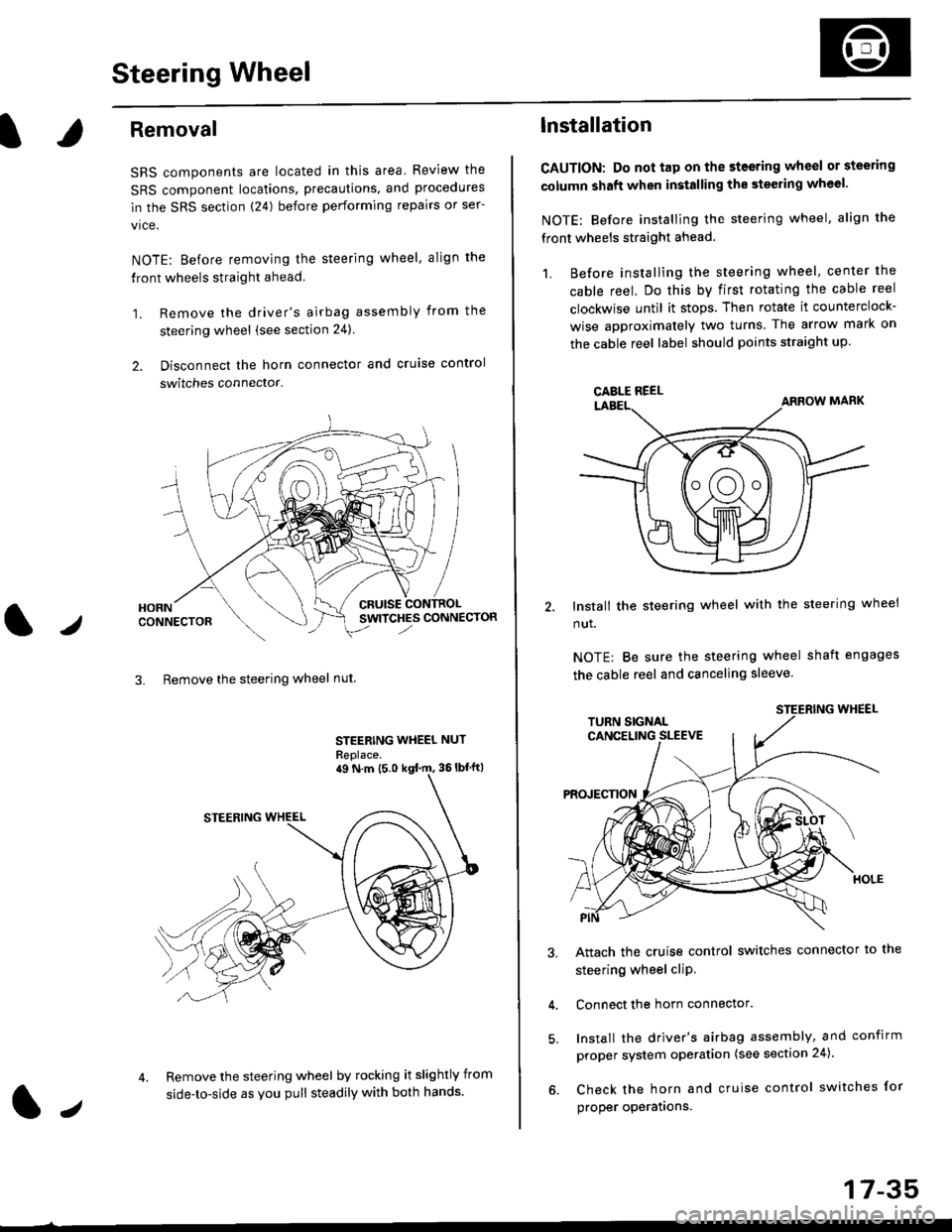
SRS components are located in this area Review the
SRS component locations, precautions, and procedures
in the SRS section (24) before performing repairs or ser-
vice.
NOTE: Before removing the steering wheel. align the
front wheels straight ahead.
1. Remove the driver's airbag assembly from the
steering wheel (see section 24)
2. Disconnect the horn connector and cruise control
switches connector.
CRUISESWITCHES CONNECTOR
3. Remove the steering wheel nut
STEERING WHEEL NUT
Replace.
Remove the steering wheel by rocking it slightly from
side-to-side as you pull steadily with both hands.
ag N.m {5.0 kgt rn, 36lbfft)
1.,
17-35
lnstallation
CAUTION: Do not tap on the steering wheel or steering
column shaft when installing the stsering wheel.
NOTE: Before installing the steering wheel, align the
front wheels straight ahead.
1. Before installing the steering wheel, center the
cable reel, Do this by first rotating the cable reel
clockwise until it stops. Then rotate it counterclock-
wise approximately two turns The arrow mark on
the cable reel label should points straight up.
Install the steering wheel with the steering wheel
nut.
NOTE: Be sure the steering wheel shaft engages
the cable reel and canceling sleeve.
Attach the cruise control switches connector io the
steering wheel cliP,
Connect the horn connector.
Install the driver's airbag assembly, and confirm
proper system operation (see section 24).
Check the horn and cruise control switches for
proper operatrons.
CAELE REEL
Page 1122 of 2189

Steering Gearbox
Installation (cont'dl
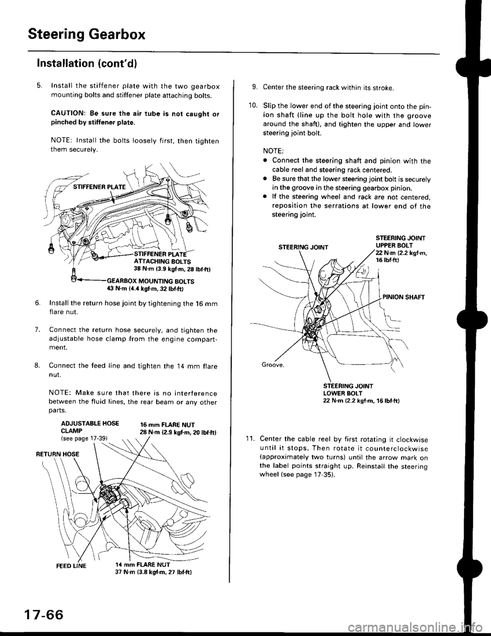
5. Install the stiffener plate with the two gearbox
mounting bolts and stiffener plate aftaching bolts.
CAUTION: Be sure the air tube is not caught orpinched by stiffener plate,
NOTE: Install the bolts loosely first, then tighten
them securely.
7.
8.
6.Install the return hose joint by tightening the l6 mm
flare nut.
Connect the relurn hose securely, and tighten the
adjustable hose clamp from the engine compart-ment.
Connect the feed line and tighten the 14 mm flare
nut.
NOTE: Make sure that there is no interference
between the fluid lines, the rear beam or any otherparts.
ADJUSTABLE HOSECLAMP(see page 17-39)
16 mm FLARE NUT28 N.m {2.9 ksl.m. 20 lbf.ft)
RETURN
1a mm FLARE NUT37 N.m (3.8 kg{.m, 27 lbt.ftl
ATTACHING AOLTS38 N.m 13.9 kgf.m, 28 lbf.ftl
MOUNTING BOLTS(} N.m (4.a kgt m, 32 lbf.ftl
17-66
9.Center the steering rack within its stroke.
Slip the lower end of the steering joint onto the pin-
ion shaft (line up the bolt hole with the groove
around the shaft), and tighten the upper and lower
steering joint bolt.
NOTE:
. Connect the steering shaft and pinion with the
cable reel and steering rack centered.. Be sure that the lower steering joint bolt is securely
in the groove in the steering gearbox pinion.
. lf the steering wheel and rack are not centered,
reposition the serrations at lower end of the
steering joint.
10.
STEERING JOINTUPPER BOLT22 N.m (2.2 kgf.m,16 tbt.ftl
PINION SHAFT
Groove,
STEERING JOINTLOWER BOLT22 N.m (2.2 kgt.m, 16lbtttl
11.Center the cable reel by first rotating it clockwise
until it stops. Then rotate it counterclockwise(approximately two turns) until the arrow mark onthe label points straight up. Reinstall the steeringwheel (see page 17 35).
Page 1182 of 2189
Rear Brake Galiper
Disassembly (cont'd)
7. Remove the piston by rotating the piston counter-clockwise with the tool, and remove the piston
boot.
CAUTION: Avoid damaging the piston.
PISTON BOOTReplace.
Remove the piston seal.
CAUTION: Take care not to damage the cylinderbore.
CALIPER BODYCheck for scoring on
9. Install the special tool between the caliper bodv andspnng cover.
CAUTION: Be caretul not to damags the inside ofthe caliper cylinder during caliper disassembty.
BRAKE SPRINGCOMPRESSOR07HAE - SG00100
11.
LOCKNUTS
Position the locknuts as shown. then turn the shaftuntil the plate just contacts the caliper body.
NOTE: Do not compress the spring under thespring cover.
Turn the shaft clockwise 1/4 -'ll2 tu.n to comoressadjusting spring B in the caliper body.
CAUTION: To preyant damage to the inner compo-nonts. do not turn the shaft mor€ than 1/2 turn.
SHAFT
LOCKNUTS
PISTON SEALReplace.
ADJUSTII{GSPRING 8
19-28